
Recommended
Recommended
More Related Content
Similar to TRANSFORMER DESIGN.pptx
Similar to TRANSFORMER DESIGN.pptx (20)
Recently uploaded
Recently uploaded (20)
TRANSFORMER DESIGN.pptx
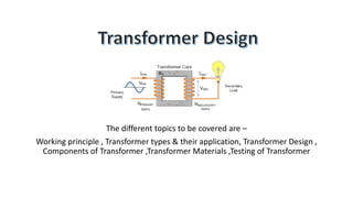
- 1. The different topics to be covered are – Working principle , Transformer types & their application, Transformer Design , Components of Transformer ,Transformer Materials ,Testing of Transformer
- 2. Basically a transformer consists of two inductive coils; primary winding and secondary winding. The coils are electrically separated but magnetically linked to each other. When, primary winding is connected to a source of alternating voltage, alternating magnetic flux is produced around the winding. The core provides magnetic path for the flux, to get linked with the secondary winding. Most of the flux gets linked with the secondary winding which is called as 'useful flux' or main 'flux', and the flux which does not get linked with secondary winding is called as 'leakage flux'. As the flux produced is alternating (the direction of it is continuously changing), EMF gets induced in the secondary winding according to Faraday's law of electromagnetic induction. This emf is called 'mutually induced emf', and the frequency of mutually induced emf is same as that of supplied emf. If the secondary winding is closed circuit, then mutually induced current flows through it, and hence the electrical energy is transferred from one circuit (primary) to another circuit (secondary)
- 3. Transformers can be classified on different basis, like types of construction, types of cooling etc. (A) On the basis of construction, transformers can be classified into two types as; 1. Core type transformer and 2. Shell type transformer, (B) On the basis of their purpose 1. Step up transformer: Voltage increases (with subsequent decrease in current) at secondary. 2. Step down transformer: Voltage decreases (with subsequent increase in current) at secondary. (C) On the basis of type of supply 1. Single phase transformer 2. Three phase transformer (D) On the basis of their use 1. Power transformer: Used in transmission network, high rating 2. Distribution transformer: Used in distribution network, comparatively lower rating than that of power transformers. 3. Special application transformers – VSD , FSD , phase shift , isolation , pad mounted , earthing transformer. The type of cooling in the transformer can be Air Natural (AN) ,Air Blast or forced (AF) , Oil Natural Air Natural (ONAN) ,Oil Natural Air Forced(ONAF),Oil Natural Water Forced(ONWF),Oil Forced Water Forced(OFWF) For voltage regulation Tap changers are provided in transformers which can be either off load or on load tap changer depending on customer requirement.
- 4. Key inputs required while designing a transformer are - Rating, Voltage ratio , Vector group , Impedance , NLL , LL , type of cooling, type of conductor , Insulation level , temperature rise , frequency. We will take example of a 1000KVA 33/0.433KV Transformer. (A) Rating - 1000KVA The power rating of a transformer is usually expressed in kVA (kilovolt-amperes), because kVA is a measure of apparent power, which is the product of the voltage and current in an AC system. (B) Voltage ratio – 33/0.433KV The ratio of voltage transformation of a transformer is equal to the number of turns on the secondary coil divided by the number of turns on the primary coil. (C) Vector Group – Dyn11 A vector group is the International Electrotechnical Commission (IEC) method of categorizing the high voltage (HV) windings and low voltage (LV) winding configurations of three-phase transformers. The vector group designation indicates the windings configurations and the difference in phase angle between them. (D) Impedance – 5% The percent impedance (%Z) is the percent of the rated load impedance possessed by a transformer. The percent impedance is important in that it allows us to: Calculate available fault currents (both individual and bank). Determine whether two transformers are suitable for paralleling. (E) NLL & LL – 1.80kw & 10.0kw No-load losses are caused by the magnetizing current needed to energize the core of the transformer, and do not vary according to the loading on the transformer. They are constant and occur 24 hours a day, 365 days a year, regardless of the load, hence the term no-load losses. Load losses vary according to the loading on the transformer. They include heat losses and eddy currents in the primary and secondary conductors of the transformer. Heat losses, or I 2R losses, in the winding materials contribute the largest part of the load losses.
- 5. (F) Type of cooling - ONAN ONAN is a form of transformer cooling in which mineral oil is used inside the transformer tank to cool and cool the transformer. KNAN is another cooling method for transformers, which means that vegetable oil is used to cool the transformer inside the oil tank. (G) Type of conductor - Electrolytic copper Copper and aluminum are the primary materials used as conductors in power-transformer windings. While aluminum is lighter and generally less expensive than copper, a larger cross section of aluminum conductor must be used to carry a current with similar performance as copper (H) Insulation Level – power frequency KVrms 70/3 , Basic Impulse level KVp 170 / NA Power frequency test - The design efficacy of the insulation system is ascertained through the one minute Power Frequency Withstand test. Impulse testing of transformers is done to determine the ability of insulation to withstand transient voltages (I) Temperature rise over ambient – Oil 45 deg , Winding 50 deg Temperature rise tests are used to make sure that a product does not get overheated during operation. This test's results are really important for the operational economy to show the performance of the transformer in the fields. The mean purpose of this test is to check whether the oil and winding temperatures of the transformer meet the values specified in the standard and technical projects.
- 6. CORE ASSEMBLY LV WINDING HV WINDING CORE COIL ASSEMBLY HV & LV CONNECTION TANKING & FITTING TESTING ACCECORY & FINAL PAINTING SKID/PSS ASSEMBLY DISPATCH Core assembly MPC copper strip MPC copper strip Press board, blocks , crepe paper Brazing rods , solder iron Transformer oil WTI , NCT PRD, PRV Open/close skid cage Silica gel breather Insulation paper Copper Foil SE conductor Job locking, support hardware Crepe paper Job locking/tank fitting hardware Marshalling box Vacuum gauge PSS enclosure Lugs & glands Cotton tape Insulation kraft paper Insulation kraft paper off load tap changer Connection lugs , ferrules Radiator as per drawing Special fuse Marshalling box & its material SF6 RMU with/without OLU Termination kit Cotton tape Cotton tape Earthing & connection CU jumper Copper flats, braided wire, MPC wire Shut off valve Ammeter CT WTI CT, NCT , special fuse, Termination kit, lugs & glands LV panel Press board Press board FRP nuts & rods Paper tube, Bakelite tube HV bushing Cable box and DC fitting Fitting & Connection accessories for PSS Adhesive tape Adhesive tape PVC sleeve , glass tube LV bushing Cable support & CB support assembly Termination kit for RMU in PSS Crepe paper Crepe paper MOG/oil gauge WTI,OTI fitting Epoxy insulator Epoxy dotted paper Drain valve/ filter valve Buchholz relay Connection flat Transformer tank Tinned CU flat, braided wire , sleeves Panel Mounting Screw/bolt SS threaded rod Epoxy insulator , SS threaded rod RD & tag plate , accessories labels , Phase & other labels Paint COMPONENTS & MATERIALS IN A FINISHED TRANSFORMER
- 7. Tests done at Factory / 3rd party labs 1. Type tests To prove that the transformer meets customer’s specifications and design expectations, the transformer has to go through different testing procedures in manufacturer premises. Some transformer tests are carried out for confirming the basic design expectation of that transformer. These tests are done mainly in a prototype unit not in all manufactured units in a lot. Type test of transformer confirms main and basic design criteria of a production lot. 2. Routine tests Routine tests of transformer is mainly for confirming the operational performance of the individual unit in a production lot. Routine tests are carried out on every unit manufactured. 3. Special tests Special tests of transformer is done as per customer requirement to obtain information useful to the user during operation or maintenance of the transformer. Tests done at Site 1. Pre-commissioning tests In addition to these, the transformer also goes through some other tests, performed on it, before actual commissioning of the transformer at the site. The transformer testing performed before commissioning the transformer at the site is called the pre- commissioning test of transformer. These tests are done to assess the condition of transformer after installation and compare the test results of all the low voltage tests with the factory test reports.
- 8. Type tests of transformer include: Winding resistance test of transformer Transformer ratio test Transformer vector group test Measurement of impedance voltage/short circuit impedance (principal tap) and load loss (Short circuit test) Measurement of no-load loss and current (Open circuit test) Measurement of insulation resistance Dielectric tests of transformer Temperature rise test of transformer Tests on on-load tap-changer Vacuum tests on tank and radiators Routine tests of transformer include Winding resistance test of transformer Transformer ratio test Transformer vector group test Measurement of impedance voltage/short circuit impedance (principal tap) and load loss (Short circuit test) Measurement of no load loss and current (Open circuit test) Measurement of insulation resistance Dielectric tests of transformer. Tests on on-load tap-changer. Oil pressure test on transformer to check against leakages past joints and gaskets That means Routine tests of transformer include all the type tests except temperature rise and vacuum tests. The oil pressure test on transformer to check against leakages past joints and gaskets is included. Special Tests of transformer include Dielectric tests. Measurement of zero-sequence impedance of three-phase transformers Short-circuit test Measurement of acoustic noise level Measurement of the harmonics of the no-load current. Measurement of the power taken by the fans and oil pumps. Tests on bought out components / accessories such as Buchholz relay, temperature indicators, pressure relief devices, oil preservation system etc.