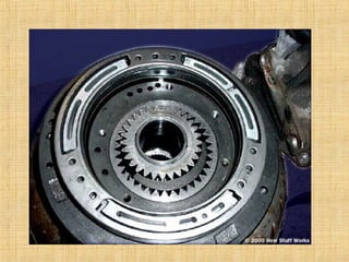
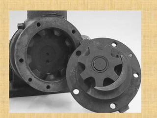
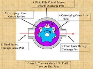
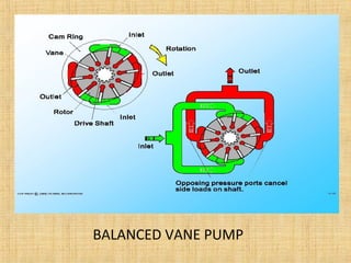
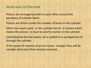
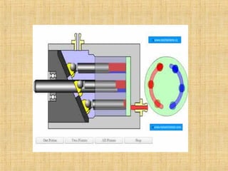
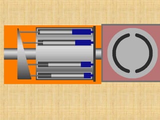
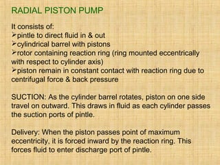
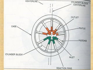
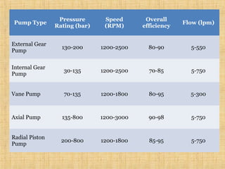
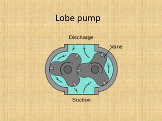
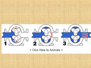
PUMPS:
Hydraulic pumps are broadly classified as positive
displacement pumps or nonpositive displacement pumps.
Nonpositive displacement pumps are used in hydrodynamic
systems to transport fluids from one location to another.
Positive displacement pumps are used in hydrostatic systems
to overcome the pressure resulting from the mechanical loads
on the system as well as the resistance to flow due to friction.
Positive displacement pumps are further classified as gear
pumps, vane pumps and piston pumps according to the
construction
A pump is a device that moves fluids (liquids or gases), or
sometimes slurries, bymechanical action. Pumps can be
classified into three major groups according to the method
they use to move the fluid: direct lift, displacement, and
gravity pumps.
A positive displacement pump has an expanding cavity
on the suction side and a decreasing cavity on discharge
side.Liquid flows into the expanding cavity and then the
same amount of liquid is discharged as the cavity
reduces.Thus a constant flow is maintained by the pump.
GEAR PUMP:
Classified as External Gear Pump and Internal Gear Pump
EXTERNAL GEAR PUMP:
Gear pumps come with a straight spur, helical, or herringbone
gears. Straight spur gears are easiest to cut and are the most
widely used. Helical and herringbone gears run more quietly, but
cost more.
Large capacity gear pumps typically use helical or herringbone
gears.
Works well up to 1500 PSI.
WORKING:
In external gear pump one gear is driven by a motor and
it in turn drives the other gear. Each gear is supported by a
shaft with bearings on both sides of the gear.
Gear pump works in following stages:
1.
As the gears come out of mesh, they
create expanding volume (vacuum) on
the inlet side of the pump.
And oil is pushed into the cavity by the
atmospheric pressure and it is trapped
by the gear teeth as they rotate.
2.
Liquid travels around the interior of
the casing in the pockets between
the teeth and the casing .
It does not pass between the gears.
3.
Finally, the unmeshing of the gears
decreases the volume and oil is
forced out of the chamber under
pressure.
Advantages:
1.Simple in structure
2.Compact
3.No overhung bearing loads
4.High pressure
5.High speed
Limitations:
1.Fixed end clearances
2.Unable to vary displacement
3.Large pulsations of flow & pressure
ANIMATION:
http://www.pumpschool.com/principles/eg_ani.htm
INTERNAL GEAR PUMP:
Exceptionally versatile
Can handle viscous as well as high temperature fluids
Gears In Constant Mesh – No Fluid
Travel At This Point
3. Fluid Fills Void & Moves
Towards Discharge Port
2. Diverging Gears
Create Suction 4.Converging Gears Expel
Fluid
1. Fluid Enters
Through Intake Port
5. Fluid Exits Through
Discharge Port
ADVANTAGES:
1.Non-pulsating discharge
2.Excellent for high-viscosity liquids
3.Constant and even discharge regardless of pressure conditions
4.Operates well in either direction
5.Can be made to operate with one direction of flow with either
rotation
6.Low NPSH required (Net Positive suction Head)
7.Single adjustable end clearance
8.Easy to maintain
9. Flexible design offers application customization
DISAVANTAGES:
1.Usually requires moderate speeds
2.Medium pressure limitations
3.One bearing runs in the product pumped
4.Overhung load on shaft bearing
VANE PUMP:
Two types : unbalanced and balanced vane pumps
Can handle low viscosity liquids
Can handle fluid temperatures -25 F to -35 F
Suitable for pressure upto 200 bar ( above for hydraulic pumps)
UNBALANCED VANE PUMP
Two rotors offset within the housing and vanes constrained by
cam ring as they cross inlet and outlet ports.
As vane tips are held against the housing, there is little leakage
and vanes compensate for wear at vane tips
However there is small leakage between rotor faces and body
sides.
Difference in pressure at inlet and outlet ports creates a severe
load on vanes and large side load on rotor shaft which leads to
failure hence called unbalanced vane pump.
BALANCED VANE PUMP
Balanced vane pump features an elliptical cam ring with two
inlet and two outlet ports.
Pressure loading occurs in pump but two identical pump
halves create equal and opposite forces on the rotor leading
to zero net force in the shaft and bearings. Hence ths pump
is called as balanced vane pump.
This pump offers improved service life than unbalanced
pump.
(hydraulics and pneumatics by andre parr—page no 45, 46)
ADVANTAGES:
1.Handles thin liquids at relatively higher pressures
2.Compensates for wear through vane extension
3.Sometimes preferred for solvents, LPG
4.Can run dry for short periods
5.Can have one seal
6.Develops good vacuum
DISADVANTAGES:
1.Complex housing and many parts
2.Not suitable for high pressures
3.Not suitable for high viscosity
4.Not good with abrasives
ANIMATION:
http://www.pumpschool.com/principles/vane_ani.htm
PISTON PUMPS:
Pumping effected by reciprocating piston in finely machined and
polished bore in cylindrical block
Piston allows oil to be drawn in while retracting
Oil is expelled from the cylinder during forward stroke of the piston.
Classification:
1.fixed displacement pump
2.variable displacement pump
As per geometry and physical arrangement classification is:
1.in line crank shaft driven pump
2.axial piston pump
3.radial piston pump
INLINE AXIAL PISTON PUMP
Pistons are arranged parallel to each other around the
periphery of cylinder block.
Pistons are driven inside the number of bores in the cylinder.
Either the swash plate or the cylinder barrel is rotated which
makes the pistons to have to and fro motion in the cylinder.
Controlled by the ball valves, oil is sucked in or pumped out of
through the cylinder.
If the speed of rotation of prime mover changes flow will be
variable otherwise flow remains constant.
BENT AXIS PUMP
Pistons are at an angle to the drive shaft and thrust plate. The
piston block shaft is connected to the drive shaft by a universal
joint.
The drive shaft, thrust plate, piston block shaft, and piston block all
revolve. The connecting rods are attached to the thrust plate and
revolve with it, unlike the swash plate pump where the piston rods
slide past a stationary swash plate.
The outlet ports are semi-circular holes in the Valve Plate.
As the pump revolves, half the pistons suck in fluid as they pass
over the intake port. The other pistons discharge their fluid through
the outlet port.
USED FOR HIGH PRESSURE AND HEAVY DUTY APPLICATIONS.
RADIAL PISTON PUMP
It consists of:
pintle to direct fluid in & out
cylindrical barrel with pistons
rotor containing reaction ring (ring mounted eccentrically
with respect to cylinder axis)
piston remain in constant contact with reaction ring due to
centrifugal force & back pressure
SUCTION: As the cylinder barrel rotates, piston on one side
travel on outward. This draws in fluid as each cylinder passes
the suction ports of pintle.
Delivery: When the piston passes point of maximum
eccentricity, it is forced inward by the reaction ring. This
forces fluid to enter discharge port of pintle.
Pressure range: 3000 to 12000PSI
Efficiency: 85 to 95 %
Flow capacity: 1 to 200 GPM
Pump Type
Pressure
Rating (bar)
Speed
(RPM)
Overall
efficiency
Flow (lpm)
External Gear
Pump
130-200 1200-2500 80-90 5-550
Internal Gear
Pump
30-135 1200-2500 70-85 5-750
Vane Pump 70-135 1200-1800 80-95 5-300
Axial Pump 135-800 1200-3000 90-98 5-750
Radial Piston
Pump
200-800 1200-1800 85-95 5-750
Lobe pump
Screw Pump

Hydraulic Pumps

  • 1.
    PUMPS: Hydraulic pumps arebroadly classified as positive displacement pumps or nonpositive displacement pumps. Nonpositive displacement pumps are used in hydrodynamic systems to transport fluids from one location to another. Positive displacement pumps are used in hydrostatic systems to overcome the pressure resulting from the mechanical loads on the system as well as the resistance to flow due to friction. Positive displacement pumps are further classified as gear pumps, vane pumps and piston pumps according to the construction
  • 2.
    A pump isa device that moves fluids (liquids or gases), or sometimes slurries, bymechanical action. Pumps can be classified into three major groups according to the method they use to move the fluid: direct lift, displacement, and gravity pumps. A positive displacement pump has an expanding cavity on the suction side and a decreasing cavity on discharge side.Liquid flows into the expanding cavity and then the same amount of liquid is discharged as the cavity reduces.Thus a constant flow is maintained by the pump.
  • 3.
    GEAR PUMP: Classified asExternal Gear Pump and Internal Gear Pump EXTERNAL GEAR PUMP: Gear pumps come with a straight spur, helical, or herringbone gears. Straight spur gears are easiest to cut and are the most widely used. Helical and herringbone gears run more quietly, but cost more. Large capacity gear pumps typically use helical or herringbone gears. Works well up to 1500 PSI.
  • 4.
    WORKING: In external gearpump one gear is driven by a motor and it in turn drives the other gear. Each gear is supported by a shaft with bearings on both sides of the gear. Gear pump works in following stages: 1. As the gears come out of mesh, they create expanding volume (vacuum) on the inlet side of the pump. And oil is pushed into the cavity by the atmospheric pressure and it is trapped by the gear teeth as they rotate.
  • 5.
    2. Liquid travels aroundthe interior of the casing in the pockets between the teeth and the casing . It does not pass between the gears. 3. Finally, the unmeshing of the gears decreases the volume and oil is forced out of the chamber under pressure.
  • 6.
    Advantages: 1.Simple in structure 2.Compact 3.Nooverhung bearing loads 4.High pressure 5.High speed Limitations: 1.Fixed end clearances 2.Unable to vary displacement 3.Large pulsations of flow & pressure ANIMATION: http://www.pumpschool.com/principles/eg_ani.htm
  • 7.
    INTERNAL GEAR PUMP: Exceptionallyversatile Can handle viscous as well as high temperature fluids
  • 11.
    Gears In ConstantMesh – No Fluid Travel At This Point 3. Fluid Fills Void & Moves Towards Discharge Port 2. Diverging Gears Create Suction 4.Converging Gears Expel Fluid 1. Fluid Enters Through Intake Port 5. Fluid Exits Through Discharge Port
  • 12.
    ADVANTAGES: 1.Non-pulsating discharge 2.Excellent forhigh-viscosity liquids 3.Constant and even discharge regardless of pressure conditions 4.Operates well in either direction 5.Can be made to operate with one direction of flow with either rotation 6.Low NPSH required (Net Positive suction Head) 7.Single adjustable end clearance 8.Easy to maintain 9. Flexible design offers application customization DISAVANTAGES: 1.Usually requires moderate speeds 2.Medium pressure limitations 3.One bearing runs in the product pumped 4.Overhung load on shaft bearing
  • 13.
    VANE PUMP: Two types: unbalanced and balanced vane pumps Can handle low viscosity liquids Can handle fluid temperatures -25 F to -35 F Suitable for pressure upto 200 bar ( above for hydraulic pumps)
  • 14.
  • 16.
    Two rotors offsetwithin the housing and vanes constrained by cam ring as they cross inlet and outlet ports. As vane tips are held against the housing, there is little leakage and vanes compensate for wear at vane tips However there is small leakage between rotor faces and body sides. Difference in pressure at inlet and outlet ports creates a severe load on vanes and large side load on rotor shaft which leads to failure hence called unbalanced vane pump.
  • 17.
  • 18.
    Balanced vane pumpfeatures an elliptical cam ring with two inlet and two outlet ports. Pressure loading occurs in pump but two identical pump halves create equal and opposite forces on the rotor leading to zero net force in the shaft and bearings. Hence ths pump is called as balanced vane pump. This pump offers improved service life than unbalanced pump. (hydraulics and pneumatics by andre parr—page no 45, 46)
  • 19.
    ADVANTAGES: 1.Handles thin liquidsat relatively higher pressures 2.Compensates for wear through vane extension 3.Sometimes preferred for solvents, LPG 4.Can run dry for short periods 5.Can have one seal 6.Develops good vacuum DISADVANTAGES: 1.Complex housing and many parts 2.Not suitable for high pressures 3.Not suitable for high viscosity 4.Not good with abrasives ANIMATION: http://www.pumpschool.com/principles/vane_ani.htm
  • 20.
    PISTON PUMPS: Pumping effectedby reciprocating piston in finely machined and polished bore in cylindrical block Piston allows oil to be drawn in while retracting Oil is expelled from the cylinder during forward stroke of the piston. Classification: 1.fixed displacement pump 2.variable displacement pump As per geometry and physical arrangement classification is: 1.in line crank shaft driven pump 2.axial piston pump 3.radial piston pump
  • 22.
    INLINE AXIAL PISTONPUMP Pistons are arranged parallel to each other around the periphery of cylinder block. Pistons are driven inside the number of bores in the cylinder. Either the swash plate or the cylinder barrel is rotated which makes the pistons to have to and fro motion in the cylinder. Controlled by the ball valves, oil is sucked in or pumped out of through the cylinder. If the speed of rotation of prime mover changes flow will be variable otherwise flow remains constant.
  • 25.
    BENT AXIS PUMP Pistonsare at an angle to the drive shaft and thrust plate. The piston block shaft is connected to the drive shaft by a universal joint. The drive shaft, thrust plate, piston block shaft, and piston block all revolve. The connecting rods are attached to the thrust plate and revolve with it, unlike the swash plate pump where the piston rods slide past a stationary swash plate. The outlet ports are semi-circular holes in the Valve Plate. As the pump revolves, half the pistons suck in fluid as they pass over the intake port. The other pistons discharge their fluid through the outlet port. USED FOR HIGH PRESSURE AND HEAVY DUTY APPLICATIONS.
  • 27.
    RADIAL PISTON PUMP Itconsists of: pintle to direct fluid in & out cylindrical barrel with pistons rotor containing reaction ring (ring mounted eccentrically with respect to cylinder axis) piston remain in constant contact with reaction ring due to centrifugal force & back pressure SUCTION: As the cylinder barrel rotates, piston on one side travel on outward. This draws in fluid as each cylinder passes the suction ports of pintle. Delivery: When the piston passes point of maximum eccentricity, it is forced inward by the reaction ring. This forces fluid to enter discharge port of pintle.
  • 29.
    Pressure range: 3000to 12000PSI Efficiency: 85 to 95 % Flow capacity: 1 to 200 GPM
  • 30.
    Pump Type Pressure Rating (bar) Speed (RPM) Overall efficiency Flow(lpm) External Gear Pump 130-200 1200-2500 80-90 5-550 Internal Gear Pump 30-135 1200-2500 70-85 5-750 Vane Pump 70-135 1200-1800 80-95 5-300 Axial Pump 135-800 1200-3000 90-98 5-750 Radial Piston Pump 200-800 1200-1800 85-95 5-750
  • 31.
  • 33.

Editor's Notes

  • #9 Two rotating gears (rotor-large exterior gear and idler -small interior gear) unmesh at the suction side to create voids which allow atmospheric pressure to force the fluid into the pump. The spaces between the gear teeth transport the fluid on either side of a crescent( increasing, increasing moon) to the discharge side. The crescent shape divides the liquid and acts as a seal between the suction and discharge ports. The gears re-mesh to discharge the fluid