SlideShare a Scribd company logo
1 of 46
Download to read offline
1
CHAPTER-1
INTRODUCTION
1.1 BEAM:
A beam is a structure element that is capable of withstanding load primarily by
resisting against bending. The bending force induced into the material of the beam as a result
of the external loads, own weight, span and external reactions to these loads is called a
bending moment .Beams are characterized by their profile (shape of cross-section ), their
length, and their material
Beams are traditionally descriptions of building or civil engineering structural
elements, but smaller structures such as truck or automobile frames, machine frames, and
other mechanical or structural systems contain beam structures that are designed and
analyzed in a similar fashion.
Fig.1 Beam cross section
Fig.2 Beam cross section subjected to load
1.2 OVERVIEW:
Historically beams were squared timbers but are also metal, stone, or combinations of
wood and metal such as a flitch beam. Beams generally carry vertical gravitational forces but
can also be used to carry horizontal loads (e.g., loads due to an earthquake or wind or in
2
tension to resist rafter thrust as a tie beam or (usually) compression as a collar beam). The
loads carried by a beam are transferred to columns, walls, or girders, which then transfer the
force to adjacent structural compression members. In light frame construction joists may rest
on beams.
In carpentry a beam is called a plate as in a sill plate or wall plate, beam as in a summer beam
or dragon beam.
1.3 CLASSIFICATION OF BEAMS BASED ON SUPPORTS:
In engineering, beams are of several types:
1. Simply supported - a beam supported on the ends which are free to rotate and have no
moment resistance.
2. Fixed - a beam supported on both ends and restrained from rotation.
3. Over hanging - a simple beam extending beyond its support on one end.
4. Double overhanging - a simple beam with both ends extending beyond its supports on both
ends.
5. Continuous - a beam extending over more than two supports.
6. Cantilever - a projecting beam fixed only at one end.
7. Trussed - a beam strengthened by adding a cable or rod to form a truss.
1.3.1 AREA MOMENT OF INERTIA:
In the beam equation I is used to represent the second moment of area. It is commonly
known as the moment of inertia, and is the sum, about the neutral axis, of dA*r^2, where r is
the distance from the neutral axis, and dA is a small patch of area. Therefore, it encompasses
not just how much area the beam section has overall, but how far each bit of area is from the
axis, squared. The greater I is, the stiffer the beam in bending, for a given material.
1.3.2 STRESSES IN BEAMS:
Internally, beams experience compressive, tensile and shear stresses as a result of the
loads applied to them. Typically, under gravity loads, the original length of the beam is
slightly reduced to enclose a smaller radius arc at the top of the beam, resulting in
compression, while the same original beam length at the bottom of the beam is slightly
stretched to enclose a larger radius arc, and so is under tension. The same original length of
the middle of the beam, generally halfway between the top and bottom, is the same as the
radial arc of bending, and so it is under neither compression nor tension, and defines the
neutral axis (dotted line in the beam figure). Above the supports, the beam is exposed to shear
stress. There are some reinforced concrete beams in which the concrete is entirely in
compression with tensile forces taken by steel tendons. These beams are known as concrete
beams, and are fabricated to produce a compression more than the expected tension under
loading conditions. High strength steel tendons are stretched while the beam is cast over
them. Then, when the concrete has cured, the tendons are slowly released and the beam is
immediately under eccentric axial loads. This eccentric loading creates an internal moment,
and, in turn, increases the moment carrying capacity of the beam. They are commonly used
on highway bridges.
3
The primary tool for structural analysis of beams is the Euler–Bernoulli beam
equation. Other mathematical methods for determining the deflection of beams include
"method of virtual work" and the "slope deflection method". Engineers are interested in
determining deflections because the beam may be in direct contact with a brittle material such
as glass. Beam deflections are also minimized for aesthetic reasons. A visibly sagging beam,
even if structurally safe, is unsightly and to be avoided. A stiffer beam (high modulus of
elasticity and high second moment of area) produces less deflection.
Mathematical methods for determining the beam forces (internal forces of the beam
and the forces that are imposed on the beam support) include the "moment distribution
method", the force or flexibility method and the direct stiffness method.
1.4 GENERAL SHAPES:
Most beams in reinforced concrete buildings have rectangular cross sections, but a
more efficient cross section for a beam is an I or H section which is typically seen in steel
construction. Because of the parallel axis theorem and the fact that most of the material is
away from the neutral axis, the second moment of area of the beam increases, which in turn
increases the stiffness.
An I-beam is only the most efficient shape in one direction of bending: up and down
looking at the profile as an I. If the beam is bent side to side, it functions as an H where it is
less efficient. The most efficient shape for both directions in 2D is a box (a square shell)
however the most efficient shape for bending in any direction is a cylindrical shell or tube.
But, for unidirectional bending, the I or wide flange beam is superior.
Efficiency means that for the same cross sectional area (volume of beam per length)
subjected to the same loading conditions, the beam deflects less.
Other shapes, like l (angles), c (channels) or tubes, are also used in construction when there
are special requirements
1.5 THIN WALLED BEAMS:
A thin walled beam is a very useful type of beam (structure). The cross section
of thin walled beams is made up from thin panels connected among them to create closed or
open cross sections of a beam (structure). Typical closed sections include round, square, and
rectangular tubes. Open sections include I-beams, T-beams, L-beams, and so on. Thin walled
beams exist because their bending stiffness per unit cross sectional area is much higher than
that for solid cross sections such a rod or bar. In this way, stiff beams can be achieved with
minimum weight. Thin walled beams are particularly useful when the material is a composite
laminates. Pioneer work on composite laminates thin walled beams was done by Librescu.
1.6 CANTILEVER BEAM:
A cantilever is a rigid structural element, such as a beam or a plate, anchored at only
one end to a (usually vertical) support from which it is protruding. Cantilevers can also be
constructed with trusses or slabs. When subjected to a structural load, the cantilever carries
the load to the support where it is forced against by a moment and shear stress.
4
Cantilever construction allows for overhanging structures without external bracing, in
contrast to constructions supported at both ends with loads applied between the supports,
such as a simply supported beam found in a post and lintel system.
1.6.1 APPLICATIONS:
In bridges, towers, and buildings
Cantilevers are widely found in construction, notably in cantilever
bridges and balconies (see corbel). In cantilever bridges the cantilevers are usually built as
pairs, with each cantilever used to support one end of a central section. The Forth
Bridge in Scotland is an example of a cantilever truss bridge. A cantilever in a
traditionally timber framed building is called a jetty or forebay. In the southern United States
a historic barn type is the cantilever barn of log construction.
Temporary cantilevers are often used in construction. The partially constructed
structure creates a cantilever, but the completed structure does not act as a cantilever. This is
very helpful when temporary supports, or falsework, cannot be used to support the structure
while it is being built (e.g., over a busy roadway or river, or in a deep valley). So some truss
arch bridges (see Navajo Bridge) are built from each side as cantilevers until the spans reach
each other and are then jacked apart to stress them in compression before final joining.
Nearly all cable-stayed bridges are built using cantilevers as this is one of their chief
advantages. Many box girder bridges are built segmentally, or in short pieces. This type of
construction lends itself well to balanced cantilever construction where the bridge is built in
both directions from a single support.
These structures are highly based on torque and rotational equilibrium.
In an architectural application, Frank Lloyd Wright‟S Fallingwater used cantilevers to
project large balconies. The East Stand at Elland Road Stadium in Leeds was, when
completed, the largest cantilever stand in the world holding 17,000 spectators. The roof built
over the stands at Old Trafford Football Ground uses a cantilever so that no supports will
block views of the field. The old, now demolished Miami Stadium had a similar roof over the
spectator area. The largest cantilever in Europe is located at St James' Park in Newcastle-
Upon-Tyne, the home stadium of Newcastle United F.C.
Less obvious examples of cantilevers are free-standing (vertical) radio towers
without guy-wires, and chimneys, which resist being blown over by the wind through
cantilever action at their base.
1.6.2 ADVANTAGES AND DISADVANTAGES:
Advantages
 Does not require a support on the opposite side (probably the main reason you would
ever have a cantilever beam).
 Creates a negative bending moment, which can help to counteract a positive bending
moment created elsewhere. This is particular helpful in cantilevers with a backspan
where a uniform load on the backspan creates positive bending, but a uniform load on
the cantilever creates negative bending.
5
Disadvantages
 Large deflections
 Generally results in larger moments
 You either need to have a fixed support, or have a backspan and check for uplift of the
far support.
6
CHAPTER-2
LITERATURE SURVEY
2.1 Structural Damage Identification Of Cantilever Beam By Using Vibration
Technique:
Prof. V. G. Bhamre
Address of correspondence
PG Scholar, Department of Mechanical Engineering
SNDCOE & RC, Yeola, S. P. Pune, University, INDIA
ABSTRACT:
In this review paper structural damage identification work in cantilever beam is done
by using the Artificial Neural Network as diagnostic parameter. The study is based on the
concept that natural frequency is inversely proportional to the mass of the structure. Thus to
regulate the proper condition of structure, periodical frequency measurement is necessary.
But in dynamic conditions and in complicated structures frequency measurement is difficult,
for the same we reviewed various papers to identify the structural damage using various
methods. The factors which effects on the damage of structural parts like crack depth; crack
location etc. is also discussed in this work. Natural frequency is measured with the help of
fast Fourier transform by various authors and artificial neural network is also used for
identification of the damage in many papers. So in this review work we studied methods of
structural damage identification such as vibrations, finite element analysis and artificial
neural network.
CONCLUSION:
It can be conclude that cantilever beam model is sensitive to the crack location, crack
depth and vibration modes.
The crack depth and natural frequency are inversely proportional to each other while the
crack location is kept constant. While the crack depth keeping constant natural frequency
decreases with increase in crack location from the cantilever end. As cross section of square
beam have same cross and longitudinal frequency, it is suitable to take in to consideration
rectangular cross section beams since they have larger transverse frequency than longitudinal.
It is obvious that the vibration behavior of the beams is very sensitive to the crack location,
crack depth and mode number. The direction of crack does not affect the natural frequency.
Crack with larger crack to depth ratio (a/h) imparts greater reductions in natural frequency
than that of the smaller.
7
2.2 Design Of Micro Cantilever Beam For Vapour Detection Using Comsol Multi
Physics Software:
Prof. Pratishtha Deep
Address of correspondence
SENSE Department, VIT University,
VIT University Vellore, T.N, India
ABSTRACT:
This paper gives an overview of micro cantilever beam of various shapes and
materials for vapour detection. The design of micro cantilever beam, analysis and simulation
is done for each shape. The simulation is done using COMSOL Multi physics software using
structural mechanics and chemical module. The simulation results of applied force and
resulting Eigen frequencies will be analyzed for different beam structures. The vapour
analysis is done using flow cell that consists of chemical pillars in surface reactions and
deposition process which consists of active layer for adsorbing the reacting species in the
laminar flow through the flow cell.
CONCLUSION:
Eigen frequencies of different micro cantilever beam structures are computed using
COMSOL Multi physics software. SiO2 is one of the desirable materials for micro cantilever
beams for chemical detection and the different eigen frequencies for different structures
includes rectangular shaped beam with a laminar flow*105 and U Shaped with a frequency of
2.054559 *105 with maximum displacements of 3.04*106 µm, 2.36*106 µm and
3.280743*106 µm for the respective structures. For chemical species detection, chemical
pillars are utilized of which different velocity fields are studied using different physics that
includes laminar flow, surface reactions and transport of diluted species. Here the general
study of adsorption of air molecules in laminar flow of water is studied. Changing the
diffusivity constant and the reaction constant, any combination of chemical vapour and fluid
mixture can be studied.
8
2.3 Structural Analysis Of Cantilever Beam Of Jib Crane:
Professor Subim N. Khan
Address of correspondence
Department of Mechanical Engineering,
RSCOE (JSPM), Pune, India
ABSTRACT:
The study includes an investigation of the stresses, deflections, shear capacity and
lateral-torsional buckling behavior of regular I section cantilever beam of jib crane subjected
to a uniformly distributed load (self-weight) and a concentrated load at the free end. The
lateral torsional buckling is the main failure mode that controls the design of “slender”
beams. Different shapes of cantilevers are proposed in this study with different cross section,
web shapes and materials. Finite element analysis and experimental study are carried out on
both types (i.e. Regular and proposed beam) to calculate and validate results. An optimization
technique is used to optimize the solution from proposed different designs. The thickness of
the web and flange is constant for all specimens with length 3 to 6 m and tested for 250 Kg
and 500 Kg load lifting capacity. Structural analysis is done to examine the influence of the
section dimension due to point load at the free end and uniformly distributed load on
cantilever. Using the study it is observed that not only the web thickness, but also the shape
of web and sectional cross section of cantilever beam influences the resistance to lateral
torsional buckling and bending.
CONCLUSION:
This paper investigates a promising structural analysis of cantilever beam of jib crane.
A new design approach of beam shape is proposed to tackle the problems of deflection, shear
capacity and lateral torsional buckling of cantilever beam due to loading. Discussions of this
paper show that how the web tapered cantilever beam is more capable of resisting the lateral
torsional buckling and bending with high shear capacity for a given load, if compared to
regular I section cantilever beam. From the study it is observed that not only the web
thickness, but also the shape of the web and cross section of cantilever beam influences the
resistance to bending, lateral torsional buckling and shear capacity.
9
2.4 Vibration Analysis Of Tapered Beam:
Prof. R.K. Behera
Address of correspondence
Department of Mechanical Engineering
National Institute of Technology Rourkela Odisha
ABSTRACT:
Beams are very common types of structural components and it can be classified
according to their geometric configuration as uniform or taper and slender or thick. If
practically analyzed, the non-uniform beams provide a better distribution of mass and
strength than uniform beams and can meet special functional requirements in architecture,
aeronautics, robotics, and other innovative engineering applications. Design of such
structures is important to resist dynamic forces, such as wind and earthquakes. It requires the
basic knowledge of natural frequencies and mode shapes of those structures. In this research
work, the equation of motion of a double tapered cantilever Euler beam is derived to find out
the natural frequencies of the structure. Finite element formulation has been done by using
Weighted residual and Galerkin‟s method. Natural frequencies and mode shapes are obtained
for different taper ratios. The effect of taper ratio on natural frequencies and mode shapes are
evaluated and compared.
CONCLUSION:
This research work presents a simple procedure to obtain the stiffness and mass
matrices of tapered Euler‟s Bernoulli beam of rectangular cross section. The proposed
procedure is verified by the previously produced results and method. The shape functions,
mass and stiffness matrices are calculated for the beam using the Finite Element Method,
which requires less computational effort due to availability of computer program. The value
of the natural frequency converges after dividing into smaller number of elements. It has been
observed that by increasing the taper ratio „α‟ the fundamental frequency increases but an
increment in taper ratio„β‟ leads to decrement in value of fundamental frequency. Mode
shapes for different taper ratio has been plotted. Taper ratio„α‟ is more effective in decreasing
the amplitude in vertical plane, than β in the horizontal plane at higher mode. The above
result is of great use for structural members where high strength to weight ratio is required.
10
2.5 Damping Models For Structural Vibration:
Prof. Jim Woodhouse
Address Of Correspondence
Trinity College, Cambridge
ABSTRACT:
This dissertation reports a systematic study on analysis and identification of multiple
parameter damped mechanical systems. The attention is focused on viscously and non-
viscously damped multiple degree-of freedom linear vibrating systems. The non-viscous
damping model is such that the damping forces depend on the past history of motion via
convolution integrals over some kernel functions. The familiar viscous damping model is a
special case of this general linear damping model when the kernel functions have no memory.
The concept of proportional damping is critically examined and a generalized form of
proportional damping is proposed. It is shown that the proportional damping can exist even
when the damping mechanism is non-viscous. Classical modal analysis is extended to deal
with general non-viscously damped multiple degree-of freedom linear dynamic systems. The
new method is similar to the existing method with some modifications due to non-viscous
effect of the damping mechanism. The concept of (complex) elastic modes and non viscous
modes have been introduced and numerical methods are suggested to obtain them. It is
further shown that the system response can be obtained exactly in terms of these modes.
Mode orthogonality relationships, known for undamped or viscously damped systems, have
been generalized to non-viscously damped systems. Several useful results which relate the
modes with the system matrices are developed. These theoretical developments on non-
viscously damped systems, in line with classical modal analysis, give impetus towards
understanding damping mechanisms in general mechanical systems. Based on a first-order
perturbation method, an approach is suggested to the identify non-proportional viscous
damping matrix from the measured complex modes and frequencies. This approach is then
further extended to identify non-viscous damping models. Both the approaches are simple,
direct, and can be used with incomplete modal data.
CONCLUSION:
Identification of damping properties by conducting dynamic testing of structures has
been discussed. It was shown that conventional modal testing theory, the basis of which is
viscously damped linear systems, can be applied to generally damped linear systems with
reasonable accuracy. A linear-nonlinear optimization method is proposed to extract complex
modal parameters from a set of measured transfer functions. A free-free beam with
constrained layer damping is considered to illustrate the damping identification methods
developed in the previous chapters of this dissertation. Modal parameters of the beam were
extracted using the newly developed method. It was shown that the transfer functions can be
reconstructed with very good accuracy using this modal extraction procedure. The real parts
of complex frequencies and modes show good agreement with the undamped natural
frequencies and modes obtained from beam theory. It was shown that, in contrast to the
traditional viscous damping assumption, the damping properties of the beam can be
11
adequately represented by an exponential (non-viscous) damping model. This fact
emphasizes the need to incorporate non-viscous damping models in structural systems. The
effects of noise in the modal data on the identified damping properties has been investigated.
For the case of viscous damping matrix identification, it was observed that the result is very
sensitive to small errors in the real parts of complex modes while it is not very sensitive to
errors in the imaginary parts. For the identification of non-viscous damping model, the
relaxation parameter is sensitive to errors in both the real and imaginary parts, however the
associated coefficient damping matrix is not very sensitive to errors in the imaginary parts.
This fact makes the proposed method more suitable for practical problems because the real
parts of complex modes can be obtained more accurately that the imaginary parts.
12
CHAPTER-3
INTRODUCTION TO CAD
3.1 CAD
Throughout the history of our industrial society, many inventions have been patented
and whole new technologies have evolved. Perhaps the single development that has impacted
manufacturing more quickly and significantly than any previous technology is the digital
computer.
Computers are being used increasingly for both design and detailing of engineering
components in the drawing office. Computer-aided design (CAD) is defined as the
application of computers and graphics software to aid or enhance the product design from
conceptualization to documentation. CAD is most commonly associated with the use of an
interactive computer graphics system, referred to as a CAD system. Computer-aided design
systems are powerful tools and in the mechanical design and geometric modeling of products
and components.
There are several good reasons for using a CAD system to support the engineering design
function:
 To increase the productivity
 To improve the quality of the design
 To uniform design standards
 To create a manufacturing data base
 To eliminate inaccuracies caused by hand-copying of drawings and inconsistency
between
 Drawings
3.2 INTRODUCTION TO PRO/ENGINEER:
Pro/ENGINEER is the industry‟s standard 3D mechanical design suit. It is the world‟s
leading CAD/CAM /CAE software, gives a broad range of integrated solutions to cover all
aspects of product design and manufacturing. Much of its success can be attributed to its
technology which spurs its customer‟s to more quickly and consistently innovate a new
robust, parametric, feature based model, because the Pro/E technology is unmatched in this
field, in all processes, in all countries, in all kind of companies along the supply chains.
Pro/Engineer is also the perfect solution for the manufacturing enterprise, with associative
applications, robust responsiveness and web connectivity that make it the ideal flexible
engineering solution to accelerate innovations. Pro/Engineer provides easy to use solution
tailored to the needs of small, medium sized enterprises as well as large industrial
corporations in all industries, consumer goods, fabrications and assembly, electrical and
electronics goods, automotive, aerospace etc.
13
3.2.1 Advantages of Pro/Engineer:
 It is much faster and more accurate. Once a design is completed. 2D and 3D views are
readily obtainable.
 The ability to incorporate changes in the design process is possible.
 It provides a very accurate representation of model specifying all other dimensions
hidden geometry etc.
 It provides a greater flexibility for change. For example if we like to change the
dimensions of our model, all the related dimensions in design assembly,
manufacturing etc. will automatically change.
 It provides clear 3D models, which are easy to visualize and understand.
 ProE provides easy assembly of the individual parts or models created it also
decreases the time required for the assembly to a large extent.
14
3.3 3D MODEL IN CATIA:
Fig.3 I-section
Fig.4 C-Section
Fig.5 T-Section
15
CHAPTER-4
INTRODUCTION TO FEA
4.1 FEA
The Basic concept in FEA is that the body or structure may be divided into smaller
elements of finite dimensions called “Finite Elements”. The original body or the structure is
then considered as an assemblage of these elements connected at a finite number of joints
called “Nodes” or “Nodal Points”. Simple functions are chosen to approximate the
displacements over each finite element. Such assumed functions are called “shape functions”.
This will represent the displacement with in the element in terms of the displacement at the
nodes of the element.
The Finite Element Method is a mathematical tool for solving ordinary and partial
differential equations. Because it is a numerical tool, it has the ability to solve the complex
problems that can be represented in differential equations form. The applications of FEM are
limitless as regards the solution of practical design problems.
Due to high cost of computing power of years gone by, FEA has a history of being
used to solve complex and cost critical problems. Classical methods alone usually cannot
provide adequate information to determine the safe working limits of a major civil
engineering construction or an automobile or an aircraft. In the recent years, FEA has been
universally used to solve structural engineering problems. The departments, which are
heavily relied on this technology, are the automotive and aerospace industry. Due to the need
to meet the extreme demands for faster, stronger, efficient and lightweight automobiles and
aircraft, manufacturers have to rely on this technique to stay competitive.
FEA has been used routinely in high volume production and manufacturing industries for
many years, as to get a product design wrong would be detrimental. For example, if a large
manufacturer had to recall one model alone due to a hand brake design fault, they would end
up having to replace up to few millions of hand brakes. This will cause a heavier loss to the
company.
The finite element method is a very important tool for those involved in engineering design;
it is now used routinely to solve problems in the following areas.
4.2 STRUCTURAL ANALYSIS:
 Thermal analysis
 Vibrations and Dynamics
 Buckling analysis
 Acoustics
 Fluid flow simulations
 Crash simulations
 Mold flow simulations
Nowadays, even the most simple of products rely on the finite element method for design
evaluation. This is because contemporary design problems usually can not be solved as
accurately & cheaply using any other method that is currently available. Physical testing was
the norm in the years gone by, but now it is simply too expensive and time consuming also.
16
4.3 INTRODUCTION TO ANSYS:
The ANSYS program is self-contained general purpose finite element program
developed and maintained by Swanson Analysis Systems Inc. The program contain many
routines, all inter related, and all for main purpose of achieving a solution to an engineering
problem by finite element method.
ANSYS finite element analysis software enables engineers to perform the following
tasks:
 Build computer models or transfer CAD models of structures, products, components,
or systems.
 Apply operating loads or other design performance conditions
 Study physical responses ,such as stress levels, temperature distributions, or
electromagnetic fields
 Optimize a design early in the development process to reduce production costs.
 Do prototype testing in environments where it otherwise would be undesirable or
impossible
The ANSYS program has a compressive graphical user interface (GUI) that gives users
easy, interactive access to program functions, commands, documentation, and reference
material. An intuitive menu system helps users navigate through the ANSYS Program. Users
can input data using a mouse, a keyboard, or a combination of both. A graphical user
interface is available throughout the program, to guide new users through the learning process
and provide more experienced users with multiple windows, pull-down menus, dialog boxes,
tool bar and online documentation.
4.3.1 Structural Analysis:
Static analysis calculates the effects of steady loading conditions on a structure, while
ignoring inertia and damping effects, such as those caused by time-varying loads. A static
analysis, however, includes steady inertia loads (such as gravity and rotational velocity), and
time-varying loads that can be approximated as static equivalent loads (such as the static
equivalent wind and seismic loads commonly defined in many building codes).
4.3.2 Loads In A Structural Analysis:
Static analysis is used to determine the displacements, stresses, strains, and forces in
structures or components caused by loads that do not induce significant inertia and damping
effects. Steady loading and response conditions are assumed; that is, the loads and the
structure's response are assumed to vary slowly with respect to time. The kinds of loading
that can be applied in a static analysis include:
• Externally applied forces and pressures
• Steady-state inertial forces (such as gravity or rotational velocity)
• Imposed (non-zero) displacements
• Temperatures (for thermal strain)
• Fluences (for nuclear swelling)
17
4.3.3 Modal Analysis:
Any physical system can vibrate. The frequencies at which vibration naturally occurs,
and the modal shapes which the vibrating system assumes are properties of the system, and
can be determined analytically using Modal Analysis.
Modal analysis is the procedure of determining a structure's dynamic characteristics;
namely, resonant frequencies, damping values, and the associated pattern of structural
deformation called mode shapes. It also can be a starting point for another, more detailed,
dynamic analysis, such as a transient dynamic analysis, a harmonic response analysis, or a
spectrum analysis.
Modal analysis in the ANSYS family of products is a linear analysis. Any
nonlinearities, such as plasticity and contact (gap) elements, are ignored even if they are
defined. Modal analysis can be done through several mode extraction methods: subspace,
Block Lanczos, Power Dynamics, Reduced, Unsymmetrical and Damped. The damped
method allows you to include damping in the structure.
4.3.4 Uses Of Modal Analysis:
Modal analysis is used to determine the natural frequencies and mode shapes of a
structure. The natural frequencies and mode shapes are important parameters in the design of
a structure for dynamic loading conditions. They are also required to do a spectrum analysis
or a mode superposition harmonic or transient analysis. Another useful feature is modal
cyclic symmetry, which allows reviewing the mode shapes of a cyclically symmetric
structure by modeling just a sector of it.
4.3.5 Random Vibration Analysis:
A Random Vibration Analysis is a form of Spectrum Analysis.
 The spectrum is a graph of spectral value versus frequency that captures the intensity
and frequency content of time-history loads.
 Random vibration analysis is probabilistic in nature, because both input and output
quantities represent only the probability that they take on certain values
Random Vibration Analysis uses Power spectral density to quantify the loading.
 (PSD) is a statistical measure defined as the limiting mean-square value of a random
variable. It is used in random vibration analyses in which the instantaneous
magnitudes of the response can be specified only by probability distribution functions
that show the probability of the magnitude taking a particular value.
18
CHAPTER-5
STRUCTURAL ANALYSIS OF CANTILEVER BEAM
5.1 STATIC ANALYSIS OF CANTILEVER BEAM
Save Creo Model as .iges format
→→Ansys → Workbench→ Select analysis system → static structural → double click
→→Select geometry → right click → import geometry → select browse →open part → ok
→→ select mesh on work bench → right click →edit
5.1.1 CONDITION-1(I-SECTION):
Fig.6 I-Section
Double click on geometry → select geometries → edit material
Select mesh on left side part tree → right click → generate mesh →
Fig.7 Mesh Model I-Section
Select static structural right click → insert → select pressure –0.096MPa
19
Fig.8 Static structural of I-Section
Select displacement → select required area → click on apply →
Select solution right click → solve →
Solution- right click → insert → deformation → total
Solution right click → insert → strain → equivant (von-mises) →
Solution right click → insert → stress → equivant (von-mises) →
Right click on deformation → evaluate all result
20
5.1.2 MATERIAL STEEL:
Fig.9 Total Deformation
Fig.10 Von-Mises Stress
Fig.11 Von-Mises Strain
21
5.1.3 MATERIAL-STAINLESS STEEL:
Fig.12 Total Deformation
Fig.13 Von-Mises Stress
Fig.14 Von-Mises Strain
22
5.1.4 MATERIAL-CAST IRON:
Fig.15 Total Deformation
Fig.16 Von-Mises Stress
Fig.17 Von-Mises strain
23
5.2 IMPORTED MODEL FOR C-SECTION(CONDITION-2):
Fig.18 C-Section
Fig.19 Meshed model of C-section
Fig.20 Force & Displacement of C-Section
24
5.2.1 MATERIAL-STEEL:
Fig.21 Total Deformation
Fig.22 Von-Mises Strees
Fig.23 Von-Mises Strain
25
5.2.2 MATERIAL-STAINLESS STEEL:
Fig.24 Total Deformation
Fig.25 Von-Mises Stress
Fig.26 Von-Mises Strain
26
5.2.3 MATERIAL- CAST IRON:
Fig.27 Total Deformation
Fig.28 Von-Mises Stress
Fig.29 Von-Mises Strain
27
5.3 IMPORTED MODEL FOR T-SECTION (CONDITION-3):
Fig.30 Imported Model Of T-Section
Fig.31 Meshed Model Of T-Section
Fig.32 Force & Displacement Of T-Section
28
5.3.1 MATERIAL-STEEL:
Fig.33 Total Deformation
Fig.34 Von-Mises Stress
Fig.35 Von-Mises Strain
29
5.3.2 MATERIAL– STAINLESS STEEL :
Fig.36 Total Deformation
Fig.37 Von-Mises stress
Fig.38 Von-mises strain
30
5.3.3 MATERIAL - CAST IRON:
Fig.39 Total Deformation
Fig.40 Von-Mises stress
Fig.41 Von-Mises strain
31
5.4 MODAL ANALYSIS OFCANTILEVER BEAM:
Save Creo Model as .iges format
→→Ansys → Workbench→ Select analysis system → model → double click
→→Select geometry → right click → import geometry → select browse →open part → ok
→→Select modal → right click →select edit → another window will be open
5.4.1 CONDITION-1(I-SECTION):
Fig.42 I-SECTION
Select mesh on left side part tree → right click → generate mesh →
Fig.43 Mesh Model of I-Section
Select displacement → select required area → click on apply → Select solution right click
→ solve →
32
Solution right click → insert → deformation → total deformation → mode 1
Solution right click → insert → deformation → total deformation2 → mode 2
Solution right click → insert → deformation → total deformation 3→ mode 3
Right click on deformation → evaluate all result
33
5.4.2 MATERIAL-STEEL:
Fig.44 Total Deformation-1
Fig.45 Total Deformation-2
Fig.46 Total Deformation-3
34
5.4.3 MATERIAL– STAINLESS STEEL:
Fig.47 Total Deformation-1
Fig.48 Total Deformation-2
Fig.49 Total Deformation-3
35
5.4.4 MATERIAL-CAST IRON:
Fig.50 Total Deformation-1
Fig.51 Total Deformation-2
Fig.52 Total Deformation-3
36
5.5 CONDITION-2(C-SECTION):
5.5.1 MATERIAL-STEEL:
Fig.53 Total Deformation-1
Fig.54 Total Deformation-2
Fig.55 Total Deformation-3
37
5.5.2 MATERIAL- STAINLESS STEEL:
Fig.56 Total Deformation-1
Fig.57 Total Deformation-2
Fig.58 Total Deformation-3
38
5.5.3 MATERIAL-CAST IRON:
Fig.59 Total Deformation-1
Fig.60 Total deformation-2
Fig.61 Total Deformation-3
39
5.6 CONDITION-3(T-SECTION):
5.6.1 MATERIAL-STEEL:
Fig.62 Total Deformation-1
Fig.63 Total Deformation-2
Fig.64 Total Deformation-3
40
5.6.2 MATERIAL-STAINLESS STEEL:
Fig.65 Total Deformation-1
Fig.66 Total Deformation-2
Fig.67 Total Deformation-3
41
5.6.3 MATERIAL-CAST IRON:
Fig.68 Total Deformation -1
Fig.69 Total Deformation-2
Fig.70 Total Deformation-3
42
5.7 RESULT TABLES
5.7.1 Static analysis results:
I-section
Material Deformation(mm) Stress (N/mm2
) Strain
Steel 2.4219 77.836 0.00038918
Stainless steel 2.5099 78.313 0.00040577
Cast iron 4.4028 76.871 0.00069883
C-section
Material Deformation(mm) Stress (N/mm2
) Strain
Steel 10.361 169.52 0.00084759
Stainless steel 10.778 170.35 0.00088267
Cast iron 18.696 167.77 0.0015251
T-section
Material Deformation(mm) Stress (N/mm2
) Strain
Steel 4.7314 207.08 0.0010354
Stainless steel 4.9027 208.22 0.0010789
Cast iron 8.6034 204.75 0.0018614
43
5.7.2 Modal analysis results:
I-section
Material Total Deformation
1(mm)
Total Deformation
2(mm)
Total Deformation
3(mm)
Steel 9.2158 11.7 9.06
Stainless steel 9.2752 11.8 9.12
Cast iron 9.6225 12.23 9.466
C-section
Material Total Deformation
1(mm)
Total Deformation
2(mm)
Total Deformation
3(mm)
Steel 9.9427 14.092 11.479
Stainless steel 10.012 14.192 11.553
Cast iron 10.37 14.691 11.987
T-section
Material Total Deformation
1(mm)
Total Deformation
2(mm)
Total Deformation
3(mm)
Steel 13.151 13.465 10.829
Stainless steel 13.053 13.37 10.76
Cast iron 13.599 13.941 11.236
44
CHAPTER-6
6.1 CONCLUSIONS:
In this work we compared the stress and natural frequency for different material
having same I, C and T cross- sectional beam. The cantilever beam is designed and analyzed
in ANSYS. The cantilever beam which is fixed at one end is vibrated to obtain the natural
frequency, mode shapes and deflection with different sections and materials.
By observing the static analysis the deformation and stress values are less for I-
section cantilever beam at cast iron material than steel and stainless steel.
By observing the modal analysis results the deformation and frequency values are less for I-
section cantilever beam more for T-section.
So it can be conclude the cast iron material is better material for cantilever beam in
this type I-section model.
45
6.2 REFERENCES:
1. Chandradeep Kumar, Anjani Kumar Singh, Nitesh Kumar, Ajit Kumar,
"Model Analysis and Harmonic Analysis of Cantilever Beam by ANSYS"
Global journal for research analysis, 2014, Volume-3, Issue-9, PP:51- 55.
2. Dipak Kr. Maiti& P. K. Sinha. Bending and free vibration analysis of shear
deformable laminated composite beams by finite element method. Composite
Structures, 29 (1994): 421- 431
3. Teboub Y, Hajela P. Free vibration of generally layered composite beams
using symbolic computations. Composite Structures, 33 (1995): 123– 34.
4. Banerjee, J.R. Free vibration of axially loaded composite Timoshenko beams
using the dynamic stiffness matrix method. Computers & Structures, 69 (1998):
197-208
5. Bassiouni AS, Gad-Elrab RM, Elmahdy TH.Dynamic analysis for laminated
composite beams. Composite Structures, 44 (1999): 81–7.
6. Kisa “Free vibration analysis of a cantilever composite beam with multiple
cracks”. Composites Science and Technology 64, 1391–1402. 2003.
7. Tita and Carvalho “Theoretical and experimental dynamic analysis of fiber
reinforced composite beams”.Journal of the Brazilian society of Mechanical
Sciences and Engineering.Vol. xxv, No.3. 2003.
8. R.A. Jafari-Talookolaei and M.T.Ahmadian.Free Vibration Analysis of a
Cross-Ply Laminated Composite Beam on Pasternak Foundation. Journal of
Computer Science, 3 (2007): 51-56.
9. Ramanamurthy .“Damage detection in composite beam using numerical
modal analysis”.International Journal on Design and Manufacturing
Technologies, Vol.2, No.1. 2008.
10. Lu and Law “Dynamic condition assessment of a cracked beam with the
composite element model”. Mechanical Systems and Signal Processing, 23,
415–431.2009.
11. Ali and Aswan “Free vibration analysis and dynamic behavior for beams
with cracks”. International Journal of science engineering and Technology,
Vol.2, No. 2. 2009.
12. Veletsos A. S. and Newmark N. M., “A method for calculating the natural
frequencies of continuousbeams”, engineering studies, Structural research,
series no. 38, University of Illinois, Urbana, January, 1953.
13.Mehdi. H et al “Modal Analysis of Composite Beam Reinforced by
Aluminium-Synthetic Fibers with and without Multiple Cracks Using ANSYS”
International journal of Mechanical Engineering, vol-4 issue-2, pp 70-80, 2014
46
14. M. Baghani, H. Mazaheri, H. Salarieh . “Analysis of large amplitude free
vibrations of clamped tapered beams on a nonlinear elastic foundation”.
Applied Mathematical Modelling. 38, 1 February 2014, 1176-1186.
15. Yuan, F.G. and R.E. Miller. A higher order finite element for laminated
composite beams. Computers & Structures, 14 (1990): 125-150.

More Related Content

What's hot

Unit 5 - deflection of beams and columns
Unit  5 - deflection of beams and columnsUnit  5 - deflection of beams and columns
Unit 5 - deflection of beams and columnskarthi keyan
 
Lecture 10 bending stresses in beams
Lecture 10 bending stresses in beamsLecture 10 bending stresses in beams
Lecture 10 bending stresses in beamsDeepak Agarwal
 
Simply supported beams
Simply supported beamsSimply supported beams
Simply supported beamsCrystalMahabir
 
Rc corbel example
Rc corbel exampleRc corbel example
Rc corbel examplemamilli
 
Analysis and design of a multi storey reinforced concrete
Analysis and design of a multi storey reinforced concreteAnalysis and design of a multi storey reinforced concrete
Analysis and design of a multi storey reinforced concreteSurat Construction PVT LTD
 
ANALYSIS & DESIGN ASPECTS OF PRE-STRESSED MEMBERS USING F.R.P. TENDONS
ANALYSIS & DESIGN ASPECTS OF PRE-STRESSED MEMBERS USING F.R.P. TENDONSANALYSIS & DESIGN ASPECTS OF PRE-STRESSED MEMBERS USING F.R.P. TENDONS
ANALYSIS & DESIGN ASPECTS OF PRE-STRESSED MEMBERS USING F.R.P. TENDONSGirish Singh
 
Types of supports in structures
Types of supports in structuresTypes of supports in structures
Types of supports in structuresAhmed Gamal
 
Introduction on Theory of Structures
Introduction on Theory of StructuresIntroduction on Theory of Structures
Introduction on Theory of Structuresandyoreta
 
Types of beam & types of supports
Types of beam & types of supportsTypes of beam & types of supports
Types of beam & types of supportsMir Zafarullah
 
Design of steel structure as per is 800(2007)
Design of steel structure as per is 800(2007)Design of steel structure as per is 800(2007)
Design of steel structure as per is 800(2007)ahsanrabbani
 
Ductile detailing IS 13920
Ductile detailing IS 13920Ductile detailing IS 13920
Ductile detailing IS 13920INTEZAAR ALAM
 
Lecture 9 shear force and bending moment in beams
Lecture 9 shear force and bending moment in beamsLecture 9 shear force and bending moment in beams
Lecture 9 shear force and bending moment in beamsDeepak Agarwal
 

What's hot (20)

Unit 5 - deflection of beams and columns
Unit  5 - deflection of beams and columnsUnit  5 - deflection of beams and columns
Unit 5 - deflection of beams and columns
 
Strength of materials
Strength of materialsStrength of materials
Strength of materials
 
Lecture 10 bending stresses in beams
Lecture 10 bending stresses in beamsLecture 10 bending stresses in beams
Lecture 10 bending stresses in beams
 
Shear centre
Shear centreShear centre
Shear centre
 
Simply supported beams
Simply supported beamsSimply supported beams
Simply supported beams
 
Beam and its types
Beam and its typesBeam and its types
Beam and its types
 
Rc corbel example
Rc corbel exampleRc corbel example
Rc corbel example
 
Cantilever Beam
Cantilever BeamCantilever Beam
Cantilever Beam
 
Analysis and design of a multi storey reinforced concrete
Analysis and design of a multi storey reinforced concreteAnalysis and design of a multi storey reinforced concrete
Analysis and design of a multi storey reinforced concrete
 
ANALYSIS & DESIGN ASPECTS OF PRE-STRESSED MEMBERS USING F.R.P. TENDONS
ANALYSIS & DESIGN ASPECTS OF PRE-STRESSED MEMBERS USING F.R.P. TENDONSANALYSIS & DESIGN ASPECTS OF PRE-STRESSED MEMBERS USING F.R.P. TENDONS
ANALYSIS & DESIGN ASPECTS OF PRE-STRESSED MEMBERS USING F.R.P. TENDONS
 
Load analysis and structural consideration
Load analysis and structural considerationLoad analysis and structural consideration
Load analysis and structural consideration
 
Types of supports in structures
Types of supports in structuresTypes of supports in structures
Types of supports in structures
 
Compression member
Compression memberCompression member
Compression member
 
Introduction on Theory of Structures
Introduction on Theory of StructuresIntroduction on Theory of Structures
Introduction on Theory of Structures
 
Types of beam & types of supports
Types of beam & types of supportsTypes of beam & types of supports
Types of beam & types of supports
 
Design of steel structure as per is 800(2007)
Design of steel structure as per is 800(2007)Design of steel structure as per is 800(2007)
Design of steel structure as per is 800(2007)
 
Unit 6: Bending and shear Stresses in beams
Unit 6: Bending and shear Stresses in beamsUnit 6: Bending and shear Stresses in beams
Unit 6: Bending and shear Stresses in beams
 
Ductile detailing IS 13920
Ductile detailing IS 13920Ductile detailing IS 13920
Ductile detailing IS 13920
 
Lecture 9 shear force and bending moment in beams
Lecture 9 shear force and bending moment in beamsLecture 9 shear force and bending moment in beams
Lecture 9 shear force and bending moment in beams
 
Types of beam
Types of beamTypes of beam
Types of beam
 

Similar to Design and analysis of cantilever beam

Beam ,Loads,Supports , trusses
Beam ,Loads,Supports , trusses Beam ,Loads,Supports , trusses
Beam ,Loads,Supports , trusses Salman Jailani
 
Overvew column analysis
Overvew column analysisOvervew column analysis
Overvew column analysisSubin Desar
 
About Bridge pier.
About Bridge pier.About Bridge pier.
About Bridge pier.Tajul Islam
 
Bridges lecture 101
Bridges lecture 101Bridges lecture 101
Bridges lecture 101koneal12
 
Form active structure system (1)
 Form active structure system (1) Form active structure system (1)
Form active structure system (1)Prince Pathania
 
Structural systems notes
Structural systems notesStructural systems notes
Structural systems notesAaqib Iqbal
 
Bridge
BridgeBridge
Bridgeillpa
 
Acm Space Frames
Acm Space FramesAcm Space Frames
Acm Space FramesAaqib Iqbal
 
FORM ACTIVE.pptx
FORM ACTIVE.pptxFORM ACTIVE.pptx
FORM ACTIVE.pptxTaranJot7
 
FORM ACTIVE.pdf
FORM ACTIVE.pdfFORM ACTIVE.pdf
FORM ACTIVE.pdfTaranJot7
 
building construction and material
building construction and materialbuilding construction and material
building construction and materialsuzain ali
 
Bridges (1)
Bridges (1)Bridges (1)
Bridges (1)wpooler
 
Stress ribbon bridge
Stress ribbon bridgeStress ribbon bridge
Stress ribbon bridgeBishnu prasad
 
Calculation Note Final
Calculation Note FinalCalculation Note Final
Calculation Note FinalMohamed Elfike
 

Similar to Design and analysis of cantilever beam (20)

Beams
Beams Beams
Beams
 
Bridges and their types
Bridges and their typesBridges and their types
Bridges and their types
 
Beam ,Loads,Supports , trusses
Beam ,Loads,Supports , trusses Beam ,Loads,Supports , trusses
Beam ,Loads,Supports , trusses
 
Overvew column analysis
Overvew column analysisOvervew column analysis
Overvew column analysis
 
About Bridge pier.
About Bridge pier.About Bridge pier.
About Bridge pier.
 
Bridges lecture 101
Bridges lecture 101Bridges lecture 101
Bridges lecture 101
 
Form active structure system (1)
 Form active structure system (1) Form active structure system (1)
Form active structure system (1)
 
Acm Unit 2
Acm Unit 2Acm Unit 2
Acm Unit 2
 
Babita
BabitaBabita
Babita
 
Structural systems notes
Structural systems notesStructural systems notes
Structural systems notes
 
Bridge
BridgeBridge
Bridge
 
Acm Space Frames
Acm Space FramesAcm Space Frames
Acm Space Frames
 
FORM ACTIVE.pptx
FORM ACTIVE.pptxFORM ACTIVE.pptx
FORM ACTIVE.pptx
 
FORM ACTIVE.pdf
FORM ACTIVE.pdfFORM ACTIVE.pdf
FORM ACTIVE.pdf
 
building construction and material
building construction and materialbuilding construction and material
building construction and material
 
Bridges (1)
Bridges (1)Bridges (1)
Bridges (1)
 
Assunit1
Assunit1Assunit1
Assunit1
 
Stress ribbon bridge
Stress ribbon bridgeStress ribbon bridge
Stress ribbon bridge
 
Calculation Note Final
Calculation Note FinalCalculation Note Final
Calculation Note Final
 
Type of building structures
Type of building structuresType of building structures
Type of building structures
 

More from College

Titile Design and analysis of cantilever beam
Titile Design and analysis of cantilever beamTitile Design and analysis of cantilever beam
Titile Design and analysis of cantilever beamCollege
 
Tables and figures serial no. Design and analysis of cantilever beam
Tables and figures serial no. Design and analysis of cantilever beamTables and figures serial no. Design and analysis of cantilever beam
Tables and figures serial no. Design and analysis of cantilever beamCollege
 
Design and analysis of cantilever beam heading
Design and analysis of cantilever beam headingDesign and analysis of cantilever beam heading
Design and analysis of cantilever beam headingCollege
 
weight optimization of lathe bed using FEA
weight optimization of lathe bed using FEAweight optimization of lathe bed using FEA
weight optimization of lathe bed using FEACollege
 
Project documents on weight optimization of lathe bed
Project documents on weight optimization of lathe bedProject documents on weight optimization of lathe bed
Project documents on weight optimization of lathe bedCollege
 
weight optimization of lathe bed using FEA
weight optimization of lathe bed using FEAweight optimization of lathe bed using FEA
weight optimization of lathe bed using FEACollege
 
Theory 1 27 forFABRICATION AND ANALYSIS OF “MIST FAN”
Theory 1 27 forFABRICATION AND ANALYSIS OF “MIST FAN”Theory 1 27 forFABRICATION AND ANALYSIS OF “MIST FAN”
Theory 1 27 forFABRICATION AND ANALYSIS OF “MIST FAN”College
 
FABRICATION AND ANALYSIS OF “MIST FAN”
FABRICATION AND ANALYSIS OF “MIST FAN”FABRICATION AND ANALYSIS OF “MIST FAN”
FABRICATION AND ANALYSIS OF “MIST FAN”College
 
List of figures FABRICATION AND ANALYSIS OF “MIST FAN”
List of figures FABRICATION AND ANALYSIS OF “MIST FAN”List of figures FABRICATION AND ANALYSIS OF “MIST FAN”
List of figures FABRICATION AND ANALYSIS OF “MIST FAN”College
 
FABRICATION AND ANALYSIS OF “MIST FAN”
FABRICATION AND ANALYSIS OF “MIST FAN”FABRICATION AND ANALYSIS OF “MIST FAN”
FABRICATION AND ANALYSIS OF “MIST FAN”College
 
Duct design .ppt
Duct design .pptDuct design .ppt
Duct design .pptCollege
 
Hvac system for outdoor air conditioning
Hvac system for outdoor air conditioningHvac system for outdoor air conditioning
Hvac system for outdoor air conditioningCollege
 
HVAC Mini project review.pptx
HVAC Mini project review.pptxHVAC Mini project review.pptx
HVAC Mini project review.pptxCollege
 
Hvac system for outdoor air conditioning
Hvac system for outdoor air conditioningHvac system for outdoor air conditioning
Hvac system for outdoor air conditioningCollege
 
Design of air conditioning duct
Design of air conditioning ductDesign of air conditioning duct
Design of air conditioning ductCollege
 

More from College (15)

Titile Design and analysis of cantilever beam
Titile Design and analysis of cantilever beamTitile Design and analysis of cantilever beam
Titile Design and analysis of cantilever beam
 
Tables and figures serial no. Design and analysis of cantilever beam
Tables and figures serial no. Design and analysis of cantilever beamTables and figures serial no. Design and analysis of cantilever beam
Tables and figures serial no. Design and analysis of cantilever beam
 
Design and analysis of cantilever beam heading
Design and analysis of cantilever beam headingDesign and analysis of cantilever beam heading
Design and analysis of cantilever beam heading
 
weight optimization of lathe bed using FEA
weight optimization of lathe bed using FEAweight optimization of lathe bed using FEA
weight optimization of lathe bed using FEA
 
Project documents on weight optimization of lathe bed
Project documents on weight optimization of lathe bedProject documents on weight optimization of lathe bed
Project documents on weight optimization of lathe bed
 
weight optimization of lathe bed using FEA
weight optimization of lathe bed using FEAweight optimization of lathe bed using FEA
weight optimization of lathe bed using FEA
 
Theory 1 27 forFABRICATION AND ANALYSIS OF “MIST FAN”
Theory 1 27 forFABRICATION AND ANALYSIS OF “MIST FAN”Theory 1 27 forFABRICATION AND ANALYSIS OF “MIST FAN”
Theory 1 27 forFABRICATION AND ANALYSIS OF “MIST FAN”
 
FABRICATION AND ANALYSIS OF “MIST FAN”
FABRICATION AND ANALYSIS OF “MIST FAN”FABRICATION AND ANALYSIS OF “MIST FAN”
FABRICATION AND ANALYSIS OF “MIST FAN”
 
List of figures FABRICATION AND ANALYSIS OF “MIST FAN”
List of figures FABRICATION AND ANALYSIS OF “MIST FAN”List of figures FABRICATION AND ANALYSIS OF “MIST FAN”
List of figures FABRICATION AND ANALYSIS OF “MIST FAN”
 
FABRICATION AND ANALYSIS OF “MIST FAN”
FABRICATION AND ANALYSIS OF “MIST FAN”FABRICATION AND ANALYSIS OF “MIST FAN”
FABRICATION AND ANALYSIS OF “MIST FAN”
 
Duct design .ppt
Duct design .pptDuct design .ppt
Duct design .ppt
 
Hvac system for outdoor air conditioning
Hvac system for outdoor air conditioningHvac system for outdoor air conditioning
Hvac system for outdoor air conditioning
 
HVAC Mini project review.pptx
HVAC Mini project review.pptxHVAC Mini project review.pptx
HVAC Mini project review.pptx
 
Hvac system for outdoor air conditioning
Hvac system for outdoor air conditioningHvac system for outdoor air conditioning
Hvac system for outdoor air conditioning
 
Design of air conditioning duct
Design of air conditioning ductDesign of air conditioning duct
Design of air conditioning duct
 

Recently uploaded

OSVC_Meta-Data based Simulation Automation to overcome Verification Challenge...
OSVC_Meta-Data based Simulation Automation to overcome Verification Challenge...OSVC_Meta-Data based Simulation Automation to overcome Verification Challenge...
OSVC_Meta-Data based Simulation Automation to overcome Verification Challenge...Soham Mondal
 
Porous Ceramics seminar and technical writing
Porous Ceramics seminar and technical writingPorous Ceramics seminar and technical writing
Porous Ceramics seminar and technical writingrakeshbaidya232001
 
Decoding Kotlin - Your guide to solving the mysterious in Kotlin.pptx
Decoding Kotlin - Your guide to solving the mysterious in Kotlin.pptxDecoding Kotlin - Your guide to solving the mysterious in Kotlin.pptx
Decoding Kotlin - Your guide to solving the mysterious in Kotlin.pptxJoão Esperancinha
 
VIP Call Girls Service Hitech City Hyderabad Call +91-8250192130
VIP Call Girls Service Hitech City Hyderabad Call +91-8250192130VIP Call Girls Service Hitech City Hyderabad Call +91-8250192130
VIP Call Girls Service Hitech City Hyderabad Call +91-8250192130Suhani Kapoor
 
Call Girls Service Nashik Vaishnavi 7001305949 Independent Escort Service Nashik
Call Girls Service Nashik Vaishnavi 7001305949 Independent Escort Service NashikCall Girls Service Nashik Vaishnavi 7001305949 Independent Escort Service Nashik
Call Girls Service Nashik Vaishnavi 7001305949 Independent Escort Service NashikCall Girls in Nagpur High Profile
 
(SHREYA) Chakan Call Girls Just Call 7001035870 [ Cash on Delivery ] Pune Esc...
(SHREYA) Chakan Call Girls Just Call 7001035870 [ Cash on Delivery ] Pune Esc...(SHREYA) Chakan Call Girls Just Call 7001035870 [ Cash on Delivery ] Pune Esc...
(SHREYA) Chakan Call Girls Just Call 7001035870 [ Cash on Delivery ] Pune Esc...ranjana rawat
 
247267395-1-Symmetric-and-distributed-shared-memory-architectures-ppt (1).ppt
247267395-1-Symmetric-and-distributed-shared-memory-architectures-ppt (1).ppt247267395-1-Symmetric-and-distributed-shared-memory-architectures-ppt (1).ppt
247267395-1-Symmetric-and-distributed-shared-memory-architectures-ppt (1).pptssuser5c9d4b1
 
Call Girls Service Nagpur Tanvi Call 7001035870 Meet With Nagpur Escorts
Call Girls Service Nagpur Tanvi Call 7001035870 Meet With Nagpur EscortsCall Girls Service Nagpur Tanvi Call 7001035870 Meet With Nagpur Escorts
Call Girls Service Nagpur Tanvi Call 7001035870 Meet With Nagpur EscortsCall Girls in Nagpur High Profile
 
(ANVI) Koregaon Park Call Girls Just Call 7001035870 [ Cash on Delivery ] Pun...
(ANVI) Koregaon Park Call Girls Just Call 7001035870 [ Cash on Delivery ] Pun...(ANVI) Koregaon Park Call Girls Just Call 7001035870 [ Cash on Delivery ] Pun...
(ANVI) Koregaon Park Call Girls Just Call 7001035870 [ Cash on Delivery ] Pun...ranjana rawat
 
Processing & Properties of Floor and Wall Tiles.pptx
Processing & Properties of Floor and Wall Tiles.pptxProcessing & Properties of Floor and Wall Tiles.pptx
Processing & Properties of Floor and Wall Tiles.pptxpranjaldaimarysona
 
the ladakh protest in leh ladakh 2024 sonam wangchuk.pptx
the ladakh protest in leh ladakh 2024 sonam wangchuk.pptxthe ladakh protest in leh ladakh 2024 sonam wangchuk.pptx
the ladakh protest in leh ladakh 2024 sonam wangchuk.pptxhumanexperienceaaa
 
The Most Attractive Pune Call Girls Budhwar Peth 8250192130 Will You Miss Thi...
The Most Attractive Pune Call Girls Budhwar Peth 8250192130 Will You Miss Thi...The Most Attractive Pune Call Girls Budhwar Peth 8250192130 Will You Miss Thi...
The Most Attractive Pune Call Girls Budhwar Peth 8250192130 Will You Miss Thi...ranjana rawat
 
Call for Papers - African Journal of Biological Sciences, E-ISSN: 2663-2187, ...
Call for Papers - African Journal of Biological Sciences, E-ISSN: 2663-2187, ...Call for Papers - African Journal of Biological Sciences, E-ISSN: 2663-2187, ...
Call for Papers - African Journal of Biological Sciences, E-ISSN: 2663-2187, ...Christo Ananth
 
APPLICATIONS-AC/DC DRIVES-OPERATING CHARACTERISTICS
APPLICATIONS-AC/DC DRIVES-OPERATING CHARACTERISTICSAPPLICATIONS-AC/DC DRIVES-OPERATING CHARACTERISTICS
APPLICATIONS-AC/DC DRIVES-OPERATING CHARACTERISTICSKurinjimalarL3
 
HARMONY IN THE NATURE AND EXISTENCE - Unit-IV
HARMONY IN THE NATURE AND EXISTENCE - Unit-IVHARMONY IN THE NATURE AND EXISTENCE - Unit-IV
HARMONY IN THE NATURE AND EXISTENCE - Unit-IVRajaP95
 
(TARA) Talegaon Dabhade Call Girls Just Call 7001035870 [ Cash on Delivery ] ...
(TARA) Talegaon Dabhade Call Girls Just Call 7001035870 [ Cash on Delivery ] ...(TARA) Talegaon Dabhade Call Girls Just Call 7001035870 [ Cash on Delivery ] ...
(TARA) Talegaon Dabhade Call Girls Just Call 7001035870 [ Cash on Delivery ] ...ranjana rawat
 
Microscopic Analysis of Ceramic Materials.pptx
Microscopic Analysis of Ceramic Materials.pptxMicroscopic Analysis of Ceramic Materials.pptx
Microscopic Analysis of Ceramic Materials.pptxpurnimasatapathy1234
 
(PRIYA) Rajgurunagar Call Girls Just Call 7001035870 [ Cash on Delivery ] Pun...
(PRIYA) Rajgurunagar Call Girls Just Call 7001035870 [ Cash on Delivery ] Pun...(PRIYA) Rajgurunagar Call Girls Just Call 7001035870 [ Cash on Delivery ] Pun...
(PRIYA) Rajgurunagar Call Girls Just Call 7001035870 [ Cash on Delivery ] Pun...ranjana rawat
 

Recently uploaded (20)

OSVC_Meta-Data based Simulation Automation to overcome Verification Challenge...
OSVC_Meta-Data based Simulation Automation to overcome Verification Challenge...OSVC_Meta-Data based Simulation Automation to overcome Verification Challenge...
OSVC_Meta-Data based Simulation Automation to overcome Verification Challenge...
 
Porous Ceramics seminar and technical writing
Porous Ceramics seminar and technical writingPorous Ceramics seminar and technical writing
Porous Ceramics seminar and technical writing
 
Decoding Kotlin - Your guide to solving the mysterious in Kotlin.pptx
Decoding Kotlin - Your guide to solving the mysterious in Kotlin.pptxDecoding Kotlin - Your guide to solving the mysterious in Kotlin.pptx
Decoding Kotlin - Your guide to solving the mysterious in Kotlin.pptx
 
VIP Call Girls Service Hitech City Hyderabad Call +91-8250192130
VIP Call Girls Service Hitech City Hyderabad Call +91-8250192130VIP Call Girls Service Hitech City Hyderabad Call +91-8250192130
VIP Call Girls Service Hitech City Hyderabad Call +91-8250192130
 
Call Girls Service Nashik Vaishnavi 7001305949 Independent Escort Service Nashik
Call Girls Service Nashik Vaishnavi 7001305949 Independent Escort Service NashikCall Girls Service Nashik Vaishnavi 7001305949 Independent Escort Service Nashik
Call Girls Service Nashik Vaishnavi 7001305949 Independent Escort Service Nashik
 
(SHREYA) Chakan Call Girls Just Call 7001035870 [ Cash on Delivery ] Pune Esc...
(SHREYA) Chakan Call Girls Just Call 7001035870 [ Cash on Delivery ] Pune Esc...(SHREYA) Chakan Call Girls Just Call 7001035870 [ Cash on Delivery ] Pune Esc...
(SHREYA) Chakan Call Girls Just Call 7001035870 [ Cash on Delivery ] Pune Esc...
 
DJARUM4D - SLOT GACOR ONLINE | SLOT DEMO ONLINE
DJARUM4D - SLOT GACOR ONLINE | SLOT DEMO ONLINEDJARUM4D - SLOT GACOR ONLINE | SLOT DEMO ONLINE
DJARUM4D - SLOT GACOR ONLINE | SLOT DEMO ONLINE
 
247267395-1-Symmetric-and-distributed-shared-memory-architectures-ppt (1).ppt
247267395-1-Symmetric-and-distributed-shared-memory-architectures-ppt (1).ppt247267395-1-Symmetric-and-distributed-shared-memory-architectures-ppt (1).ppt
247267395-1-Symmetric-and-distributed-shared-memory-architectures-ppt (1).ppt
 
Roadmap to Membership of RICS - Pathways and Routes
Roadmap to Membership of RICS - Pathways and RoutesRoadmap to Membership of RICS - Pathways and Routes
Roadmap to Membership of RICS - Pathways and Routes
 
Call Girls Service Nagpur Tanvi Call 7001035870 Meet With Nagpur Escorts
Call Girls Service Nagpur Tanvi Call 7001035870 Meet With Nagpur EscortsCall Girls Service Nagpur Tanvi Call 7001035870 Meet With Nagpur Escorts
Call Girls Service Nagpur Tanvi Call 7001035870 Meet With Nagpur Escorts
 
(ANVI) Koregaon Park Call Girls Just Call 7001035870 [ Cash on Delivery ] Pun...
(ANVI) Koregaon Park Call Girls Just Call 7001035870 [ Cash on Delivery ] Pun...(ANVI) Koregaon Park Call Girls Just Call 7001035870 [ Cash on Delivery ] Pun...
(ANVI) Koregaon Park Call Girls Just Call 7001035870 [ Cash on Delivery ] Pun...
 
Processing & Properties of Floor and Wall Tiles.pptx
Processing & Properties of Floor and Wall Tiles.pptxProcessing & Properties of Floor and Wall Tiles.pptx
Processing & Properties of Floor and Wall Tiles.pptx
 
the ladakh protest in leh ladakh 2024 sonam wangchuk.pptx
the ladakh protest in leh ladakh 2024 sonam wangchuk.pptxthe ladakh protest in leh ladakh 2024 sonam wangchuk.pptx
the ladakh protest in leh ladakh 2024 sonam wangchuk.pptx
 
The Most Attractive Pune Call Girls Budhwar Peth 8250192130 Will You Miss Thi...
The Most Attractive Pune Call Girls Budhwar Peth 8250192130 Will You Miss Thi...The Most Attractive Pune Call Girls Budhwar Peth 8250192130 Will You Miss Thi...
The Most Attractive Pune Call Girls Budhwar Peth 8250192130 Will You Miss Thi...
 
Call for Papers - African Journal of Biological Sciences, E-ISSN: 2663-2187, ...
Call for Papers - African Journal of Biological Sciences, E-ISSN: 2663-2187, ...Call for Papers - African Journal of Biological Sciences, E-ISSN: 2663-2187, ...
Call for Papers - African Journal of Biological Sciences, E-ISSN: 2663-2187, ...
 
APPLICATIONS-AC/DC DRIVES-OPERATING CHARACTERISTICS
APPLICATIONS-AC/DC DRIVES-OPERATING CHARACTERISTICSAPPLICATIONS-AC/DC DRIVES-OPERATING CHARACTERISTICS
APPLICATIONS-AC/DC DRIVES-OPERATING CHARACTERISTICS
 
HARMONY IN THE NATURE AND EXISTENCE - Unit-IV
HARMONY IN THE NATURE AND EXISTENCE - Unit-IVHARMONY IN THE NATURE AND EXISTENCE - Unit-IV
HARMONY IN THE NATURE AND EXISTENCE - Unit-IV
 
(TARA) Talegaon Dabhade Call Girls Just Call 7001035870 [ Cash on Delivery ] ...
(TARA) Talegaon Dabhade Call Girls Just Call 7001035870 [ Cash on Delivery ] ...(TARA) Talegaon Dabhade Call Girls Just Call 7001035870 [ Cash on Delivery ] ...
(TARA) Talegaon Dabhade Call Girls Just Call 7001035870 [ Cash on Delivery ] ...
 
Microscopic Analysis of Ceramic Materials.pptx
Microscopic Analysis of Ceramic Materials.pptxMicroscopic Analysis of Ceramic Materials.pptx
Microscopic Analysis of Ceramic Materials.pptx
 
(PRIYA) Rajgurunagar Call Girls Just Call 7001035870 [ Cash on Delivery ] Pun...
(PRIYA) Rajgurunagar Call Girls Just Call 7001035870 [ Cash on Delivery ] Pun...(PRIYA) Rajgurunagar Call Girls Just Call 7001035870 [ Cash on Delivery ] Pun...
(PRIYA) Rajgurunagar Call Girls Just Call 7001035870 [ Cash on Delivery ] Pun...
 

Design and analysis of cantilever beam

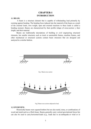
  • 1. 1 CHAPTER-1 INTRODUCTION 1.1 BEAM: A beam is a structure element that is capable of withstanding load primarily by resisting against bending. The bending force induced into the material of the beam as a result of the external loads, own weight, span and external reactions to these loads is called a bending moment .Beams are characterized by their profile (shape of cross-section ), their length, and their material Beams are traditionally descriptions of building or civil engineering structural elements, but smaller structures such as truck or automobile frames, machine frames, and other mechanical or structural systems contain beam structures that are designed and analyzed in a similar fashion. Fig.1 Beam cross section Fig.2 Beam cross section subjected to load 1.2 OVERVIEW: Historically beams were squared timbers but are also metal, stone, or combinations of wood and metal such as a flitch beam. Beams generally carry vertical gravitational forces but can also be used to carry horizontal loads (e.g., loads due to an earthquake or wind or in
  • 2. 2 tension to resist rafter thrust as a tie beam or (usually) compression as a collar beam). The loads carried by a beam are transferred to columns, walls, or girders, which then transfer the force to adjacent structural compression members. In light frame construction joists may rest on beams. In carpentry a beam is called a plate as in a sill plate or wall plate, beam as in a summer beam or dragon beam. 1.3 CLASSIFICATION OF BEAMS BASED ON SUPPORTS: In engineering, beams are of several types: 1. Simply supported - a beam supported on the ends which are free to rotate and have no moment resistance. 2. Fixed - a beam supported on both ends and restrained from rotation. 3. Over hanging - a simple beam extending beyond its support on one end. 4. Double overhanging - a simple beam with both ends extending beyond its supports on both ends. 5. Continuous - a beam extending over more than two supports. 6. Cantilever - a projecting beam fixed only at one end. 7. Trussed - a beam strengthened by adding a cable or rod to form a truss. 1.3.1 AREA MOMENT OF INERTIA: In the beam equation I is used to represent the second moment of area. It is commonly known as the moment of inertia, and is the sum, about the neutral axis, of dA*r^2, where r is the distance from the neutral axis, and dA is a small patch of area. Therefore, it encompasses not just how much area the beam section has overall, but how far each bit of area is from the axis, squared. The greater I is, the stiffer the beam in bending, for a given material. 1.3.2 STRESSES IN BEAMS: Internally, beams experience compressive, tensile and shear stresses as a result of the loads applied to them. Typically, under gravity loads, the original length of the beam is slightly reduced to enclose a smaller radius arc at the top of the beam, resulting in compression, while the same original beam length at the bottom of the beam is slightly stretched to enclose a larger radius arc, and so is under tension. The same original length of the middle of the beam, generally halfway between the top and bottom, is the same as the radial arc of bending, and so it is under neither compression nor tension, and defines the neutral axis (dotted line in the beam figure). Above the supports, the beam is exposed to shear stress. There are some reinforced concrete beams in which the concrete is entirely in compression with tensile forces taken by steel tendons. These beams are known as concrete beams, and are fabricated to produce a compression more than the expected tension under loading conditions. High strength steel tendons are stretched while the beam is cast over them. Then, when the concrete has cured, the tendons are slowly released and the beam is immediately under eccentric axial loads. This eccentric loading creates an internal moment, and, in turn, increases the moment carrying capacity of the beam. They are commonly used on highway bridges.
  • 3. 3 The primary tool for structural analysis of beams is the Euler–Bernoulli beam equation. Other mathematical methods for determining the deflection of beams include "method of virtual work" and the "slope deflection method". Engineers are interested in determining deflections because the beam may be in direct contact with a brittle material such as glass. Beam deflections are also minimized for aesthetic reasons. A visibly sagging beam, even if structurally safe, is unsightly and to be avoided. A stiffer beam (high modulus of elasticity and high second moment of area) produces less deflection. Mathematical methods for determining the beam forces (internal forces of the beam and the forces that are imposed on the beam support) include the "moment distribution method", the force or flexibility method and the direct stiffness method. 1.4 GENERAL SHAPES: Most beams in reinforced concrete buildings have rectangular cross sections, but a more efficient cross section for a beam is an I or H section which is typically seen in steel construction. Because of the parallel axis theorem and the fact that most of the material is away from the neutral axis, the second moment of area of the beam increases, which in turn increases the stiffness. An I-beam is only the most efficient shape in one direction of bending: up and down looking at the profile as an I. If the beam is bent side to side, it functions as an H where it is less efficient. The most efficient shape for both directions in 2D is a box (a square shell) however the most efficient shape for bending in any direction is a cylindrical shell or tube. But, for unidirectional bending, the I or wide flange beam is superior. Efficiency means that for the same cross sectional area (volume of beam per length) subjected to the same loading conditions, the beam deflects less. Other shapes, like l (angles), c (channels) or tubes, are also used in construction when there are special requirements 1.5 THIN WALLED BEAMS: A thin walled beam is a very useful type of beam (structure). The cross section of thin walled beams is made up from thin panels connected among them to create closed or open cross sections of a beam (structure). Typical closed sections include round, square, and rectangular tubes. Open sections include I-beams, T-beams, L-beams, and so on. Thin walled beams exist because their bending stiffness per unit cross sectional area is much higher than that for solid cross sections such a rod or bar. In this way, stiff beams can be achieved with minimum weight. Thin walled beams are particularly useful when the material is a composite laminates. Pioneer work on composite laminates thin walled beams was done by Librescu. 1.6 CANTILEVER BEAM: A cantilever is a rigid structural element, such as a beam or a plate, anchored at only one end to a (usually vertical) support from which it is protruding. Cantilevers can also be constructed with trusses or slabs. When subjected to a structural load, the cantilever carries the load to the support where it is forced against by a moment and shear stress.
  • 4. 4 Cantilever construction allows for overhanging structures without external bracing, in contrast to constructions supported at both ends with loads applied between the supports, such as a simply supported beam found in a post and lintel system. 1.6.1 APPLICATIONS: In bridges, towers, and buildings Cantilevers are widely found in construction, notably in cantilever bridges and balconies (see corbel). In cantilever bridges the cantilevers are usually built as pairs, with each cantilever used to support one end of a central section. The Forth Bridge in Scotland is an example of a cantilever truss bridge. A cantilever in a traditionally timber framed building is called a jetty or forebay. In the southern United States a historic barn type is the cantilever barn of log construction. Temporary cantilevers are often used in construction. The partially constructed structure creates a cantilever, but the completed structure does not act as a cantilever. This is very helpful when temporary supports, or falsework, cannot be used to support the structure while it is being built (e.g., over a busy roadway or river, or in a deep valley). So some truss arch bridges (see Navajo Bridge) are built from each side as cantilevers until the spans reach each other and are then jacked apart to stress them in compression before final joining. Nearly all cable-stayed bridges are built using cantilevers as this is one of their chief advantages. Many box girder bridges are built segmentally, or in short pieces. This type of construction lends itself well to balanced cantilever construction where the bridge is built in both directions from a single support. These structures are highly based on torque and rotational equilibrium. In an architectural application, Frank Lloyd Wright‟S Fallingwater used cantilevers to project large balconies. The East Stand at Elland Road Stadium in Leeds was, when completed, the largest cantilever stand in the world holding 17,000 spectators. The roof built over the stands at Old Trafford Football Ground uses a cantilever so that no supports will block views of the field. The old, now demolished Miami Stadium had a similar roof over the spectator area. The largest cantilever in Europe is located at St James' Park in Newcastle- Upon-Tyne, the home stadium of Newcastle United F.C. Less obvious examples of cantilevers are free-standing (vertical) radio towers without guy-wires, and chimneys, which resist being blown over by the wind through cantilever action at their base. 1.6.2 ADVANTAGES AND DISADVANTAGES: Advantages  Does not require a support on the opposite side (probably the main reason you would ever have a cantilever beam).  Creates a negative bending moment, which can help to counteract a positive bending moment created elsewhere. This is particular helpful in cantilevers with a backspan where a uniform load on the backspan creates positive bending, but a uniform load on the cantilever creates negative bending.
  • 5. 5 Disadvantages  Large deflections  Generally results in larger moments  You either need to have a fixed support, or have a backspan and check for uplift of the far support.
  • 6. 6 CHAPTER-2 LITERATURE SURVEY 2.1 Structural Damage Identification Of Cantilever Beam By Using Vibration Technique: Prof. V. G. Bhamre Address of correspondence PG Scholar, Department of Mechanical Engineering SNDCOE & RC, Yeola, S. P. Pune, University, INDIA ABSTRACT: In this review paper structural damage identification work in cantilever beam is done by using the Artificial Neural Network as diagnostic parameter. The study is based on the concept that natural frequency is inversely proportional to the mass of the structure. Thus to regulate the proper condition of structure, periodical frequency measurement is necessary. But in dynamic conditions and in complicated structures frequency measurement is difficult, for the same we reviewed various papers to identify the structural damage using various methods. The factors which effects on the damage of structural parts like crack depth; crack location etc. is also discussed in this work. Natural frequency is measured with the help of fast Fourier transform by various authors and artificial neural network is also used for identification of the damage in many papers. So in this review work we studied methods of structural damage identification such as vibrations, finite element analysis and artificial neural network. CONCLUSION: It can be conclude that cantilever beam model is sensitive to the crack location, crack depth and vibration modes. The crack depth and natural frequency are inversely proportional to each other while the crack location is kept constant. While the crack depth keeping constant natural frequency decreases with increase in crack location from the cantilever end. As cross section of square beam have same cross and longitudinal frequency, it is suitable to take in to consideration rectangular cross section beams since they have larger transverse frequency than longitudinal. It is obvious that the vibration behavior of the beams is very sensitive to the crack location, crack depth and mode number. The direction of crack does not affect the natural frequency. Crack with larger crack to depth ratio (a/h) imparts greater reductions in natural frequency than that of the smaller.
  • 7. 7 2.2 Design Of Micro Cantilever Beam For Vapour Detection Using Comsol Multi Physics Software: Prof. Pratishtha Deep Address of correspondence SENSE Department, VIT University, VIT University Vellore, T.N, India ABSTRACT: This paper gives an overview of micro cantilever beam of various shapes and materials for vapour detection. The design of micro cantilever beam, analysis and simulation is done for each shape. The simulation is done using COMSOL Multi physics software using structural mechanics and chemical module. The simulation results of applied force and resulting Eigen frequencies will be analyzed for different beam structures. The vapour analysis is done using flow cell that consists of chemical pillars in surface reactions and deposition process which consists of active layer for adsorbing the reacting species in the laminar flow through the flow cell. CONCLUSION: Eigen frequencies of different micro cantilever beam structures are computed using COMSOL Multi physics software. SiO2 is one of the desirable materials for micro cantilever beams for chemical detection and the different eigen frequencies for different structures includes rectangular shaped beam with a laminar flow*105 and U Shaped with a frequency of 2.054559 *105 with maximum displacements of 3.04*106 µm, 2.36*106 µm and 3.280743*106 µm for the respective structures. For chemical species detection, chemical pillars are utilized of which different velocity fields are studied using different physics that includes laminar flow, surface reactions and transport of diluted species. Here the general study of adsorption of air molecules in laminar flow of water is studied. Changing the diffusivity constant and the reaction constant, any combination of chemical vapour and fluid mixture can be studied.
  • 8. 8 2.3 Structural Analysis Of Cantilever Beam Of Jib Crane: Professor Subim N. Khan Address of correspondence Department of Mechanical Engineering, RSCOE (JSPM), Pune, India ABSTRACT: The study includes an investigation of the stresses, deflections, shear capacity and lateral-torsional buckling behavior of regular I section cantilever beam of jib crane subjected to a uniformly distributed load (self-weight) and a concentrated load at the free end. The lateral torsional buckling is the main failure mode that controls the design of “slender” beams. Different shapes of cantilevers are proposed in this study with different cross section, web shapes and materials. Finite element analysis and experimental study are carried out on both types (i.e. Regular and proposed beam) to calculate and validate results. An optimization technique is used to optimize the solution from proposed different designs. The thickness of the web and flange is constant for all specimens with length 3 to 6 m and tested for 250 Kg and 500 Kg load lifting capacity. Structural analysis is done to examine the influence of the section dimension due to point load at the free end and uniformly distributed load on cantilever. Using the study it is observed that not only the web thickness, but also the shape of web and sectional cross section of cantilever beam influences the resistance to lateral torsional buckling and bending. CONCLUSION: This paper investigates a promising structural analysis of cantilever beam of jib crane. A new design approach of beam shape is proposed to tackle the problems of deflection, shear capacity and lateral torsional buckling of cantilever beam due to loading. Discussions of this paper show that how the web tapered cantilever beam is more capable of resisting the lateral torsional buckling and bending with high shear capacity for a given load, if compared to regular I section cantilever beam. From the study it is observed that not only the web thickness, but also the shape of the web and cross section of cantilever beam influences the resistance to bending, lateral torsional buckling and shear capacity.
  • 9. 9 2.4 Vibration Analysis Of Tapered Beam: Prof. R.K. Behera Address of correspondence Department of Mechanical Engineering National Institute of Technology Rourkela Odisha ABSTRACT: Beams are very common types of structural components and it can be classified according to their geometric configuration as uniform or taper and slender or thick. If practically analyzed, the non-uniform beams provide a better distribution of mass and strength than uniform beams and can meet special functional requirements in architecture, aeronautics, robotics, and other innovative engineering applications. Design of such structures is important to resist dynamic forces, such as wind and earthquakes. It requires the basic knowledge of natural frequencies and mode shapes of those structures. In this research work, the equation of motion of a double tapered cantilever Euler beam is derived to find out the natural frequencies of the structure. Finite element formulation has been done by using Weighted residual and Galerkin‟s method. Natural frequencies and mode shapes are obtained for different taper ratios. The effect of taper ratio on natural frequencies and mode shapes are evaluated and compared. CONCLUSION: This research work presents a simple procedure to obtain the stiffness and mass matrices of tapered Euler‟s Bernoulli beam of rectangular cross section. The proposed procedure is verified by the previously produced results and method. The shape functions, mass and stiffness matrices are calculated for the beam using the Finite Element Method, which requires less computational effort due to availability of computer program. The value of the natural frequency converges after dividing into smaller number of elements. It has been observed that by increasing the taper ratio „α‟ the fundamental frequency increases but an increment in taper ratio„β‟ leads to decrement in value of fundamental frequency. Mode shapes for different taper ratio has been plotted. Taper ratio„α‟ is more effective in decreasing the amplitude in vertical plane, than β in the horizontal plane at higher mode. The above result is of great use for structural members where high strength to weight ratio is required.
  • 10. 10 2.5 Damping Models For Structural Vibration: Prof. Jim Woodhouse Address Of Correspondence Trinity College, Cambridge ABSTRACT: This dissertation reports a systematic study on analysis and identification of multiple parameter damped mechanical systems. The attention is focused on viscously and non- viscously damped multiple degree-of freedom linear vibrating systems. The non-viscous damping model is such that the damping forces depend on the past history of motion via convolution integrals over some kernel functions. The familiar viscous damping model is a special case of this general linear damping model when the kernel functions have no memory. The concept of proportional damping is critically examined and a generalized form of proportional damping is proposed. It is shown that the proportional damping can exist even when the damping mechanism is non-viscous. Classical modal analysis is extended to deal with general non-viscously damped multiple degree-of freedom linear dynamic systems. The new method is similar to the existing method with some modifications due to non-viscous effect of the damping mechanism. The concept of (complex) elastic modes and non viscous modes have been introduced and numerical methods are suggested to obtain them. It is further shown that the system response can be obtained exactly in terms of these modes. Mode orthogonality relationships, known for undamped or viscously damped systems, have been generalized to non-viscously damped systems. Several useful results which relate the modes with the system matrices are developed. These theoretical developments on non- viscously damped systems, in line with classical modal analysis, give impetus towards understanding damping mechanisms in general mechanical systems. Based on a first-order perturbation method, an approach is suggested to the identify non-proportional viscous damping matrix from the measured complex modes and frequencies. This approach is then further extended to identify non-viscous damping models. Both the approaches are simple, direct, and can be used with incomplete modal data. CONCLUSION: Identification of damping properties by conducting dynamic testing of structures has been discussed. It was shown that conventional modal testing theory, the basis of which is viscously damped linear systems, can be applied to generally damped linear systems with reasonable accuracy. A linear-nonlinear optimization method is proposed to extract complex modal parameters from a set of measured transfer functions. A free-free beam with constrained layer damping is considered to illustrate the damping identification methods developed in the previous chapters of this dissertation. Modal parameters of the beam were extracted using the newly developed method. It was shown that the transfer functions can be reconstructed with very good accuracy using this modal extraction procedure. The real parts of complex frequencies and modes show good agreement with the undamped natural frequencies and modes obtained from beam theory. It was shown that, in contrast to the traditional viscous damping assumption, the damping properties of the beam can be
  • 11. 11 adequately represented by an exponential (non-viscous) damping model. This fact emphasizes the need to incorporate non-viscous damping models in structural systems. The effects of noise in the modal data on the identified damping properties has been investigated. For the case of viscous damping matrix identification, it was observed that the result is very sensitive to small errors in the real parts of complex modes while it is not very sensitive to errors in the imaginary parts. For the identification of non-viscous damping model, the relaxation parameter is sensitive to errors in both the real and imaginary parts, however the associated coefficient damping matrix is not very sensitive to errors in the imaginary parts. This fact makes the proposed method more suitable for practical problems because the real parts of complex modes can be obtained more accurately that the imaginary parts.
  • 12. 12 CHAPTER-3 INTRODUCTION TO CAD 3.1 CAD Throughout the history of our industrial society, many inventions have been patented and whole new technologies have evolved. Perhaps the single development that has impacted manufacturing more quickly and significantly than any previous technology is the digital computer. Computers are being used increasingly for both design and detailing of engineering components in the drawing office. Computer-aided design (CAD) is defined as the application of computers and graphics software to aid or enhance the product design from conceptualization to documentation. CAD is most commonly associated with the use of an interactive computer graphics system, referred to as a CAD system. Computer-aided design systems are powerful tools and in the mechanical design and geometric modeling of products and components. There are several good reasons for using a CAD system to support the engineering design function:  To increase the productivity  To improve the quality of the design  To uniform design standards  To create a manufacturing data base  To eliminate inaccuracies caused by hand-copying of drawings and inconsistency between  Drawings 3.2 INTRODUCTION TO PRO/ENGINEER: Pro/ENGINEER is the industry‟s standard 3D mechanical design suit. It is the world‟s leading CAD/CAM /CAE software, gives a broad range of integrated solutions to cover all aspects of product design and manufacturing. Much of its success can be attributed to its technology which spurs its customer‟s to more quickly and consistently innovate a new robust, parametric, feature based model, because the Pro/E technology is unmatched in this field, in all processes, in all countries, in all kind of companies along the supply chains. Pro/Engineer is also the perfect solution for the manufacturing enterprise, with associative applications, robust responsiveness and web connectivity that make it the ideal flexible engineering solution to accelerate innovations. Pro/Engineer provides easy to use solution tailored to the needs of small, medium sized enterprises as well as large industrial corporations in all industries, consumer goods, fabrications and assembly, electrical and electronics goods, automotive, aerospace etc.
  • 13. 13 3.2.1 Advantages of Pro/Engineer:  It is much faster and more accurate. Once a design is completed. 2D and 3D views are readily obtainable.  The ability to incorporate changes in the design process is possible.  It provides a very accurate representation of model specifying all other dimensions hidden geometry etc.  It provides a greater flexibility for change. For example if we like to change the dimensions of our model, all the related dimensions in design assembly, manufacturing etc. will automatically change.  It provides clear 3D models, which are easy to visualize and understand.  ProE provides easy assembly of the individual parts or models created it also decreases the time required for the assembly to a large extent.
  • 14. 14 3.3 3D MODEL IN CATIA: Fig.3 I-section Fig.4 C-Section Fig.5 T-Section
  • 15. 15 CHAPTER-4 INTRODUCTION TO FEA 4.1 FEA The Basic concept in FEA is that the body or structure may be divided into smaller elements of finite dimensions called “Finite Elements”. The original body or the structure is then considered as an assemblage of these elements connected at a finite number of joints called “Nodes” or “Nodal Points”. Simple functions are chosen to approximate the displacements over each finite element. Such assumed functions are called “shape functions”. This will represent the displacement with in the element in terms of the displacement at the nodes of the element. The Finite Element Method is a mathematical tool for solving ordinary and partial differential equations. Because it is a numerical tool, it has the ability to solve the complex problems that can be represented in differential equations form. The applications of FEM are limitless as regards the solution of practical design problems. Due to high cost of computing power of years gone by, FEA has a history of being used to solve complex and cost critical problems. Classical methods alone usually cannot provide adequate information to determine the safe working limits of a major civil engineering construction or an automobile or an aircraft. In the recent years, FEA has been universally used to solve structural engineering problems. The departments, which are heavily relied on this technology, are the automotive and aerospace industry. Due to the need to meet the extreme demands for faster, stronger, efficient and lightweight automobiles and aircraft, manufacturers have to rely on this technique to stay competitive. FEA has been used routinely in high volume production and manufacturing industries for many years, as to get a product design wrong would be detrimental. For example, if a large manufacturer had to recall one model alone due to a hand brake design fault, they would end up having to replace up to few millions of hand brakes. This will cause a heavier loss to the company. The finite element method is a very important tool for those involved in engineering design; it is now used routinely to solve problems in the following areas. 4.2 STRUCTURAL ANALYSIS:  Thermal analysis  Vibrations and Dynamics  Buckling analysis  Acoustics  Fluid flow simulations  Crash simulations  Mold flow simulations Nowadays, even the most simple of products rely on the finite element method for design evaluation. This is because contemporary design problems usually can not be solved as accurately & cheaply using any other method that is currently available. Physical testing was the norm in the years gone by, but now it is simply too expensive and time consuming also.
  • 16. 16 4.3 INTRODUCTION TO ANSYS: The ANSYS program is self-contained general purpose finite element program developed and maintained by Swanson Analysis Systems Inc. The program contain many routines, all inter related, and all for main purpose of achieving a solution to an engineering problem by finite element method. ANSYS finite element analysis software enables engineers to perform the following tasks:  Build computer models or transfer CAD models of structures, products, components, or systems.  Apply operating loads or other design performance conditions  Study physical responses ,such as stress levels, temperature distributions, or electromagnetic fields  Optimize a design early in the development process to reduce production costs.  Do prototype testing in environments where it otherwise would be undesirable or impossible The ANSYS program has a compressive graphical user interface (GUI) that gives users easy, interactive access to program functions, commands, documentation, and reference material. An intuitive menu system helps users navigate through the ANSYS Program. Users can input data using a mouse, a keyboard, or a combination of both. A graphical user interface is available throughout the program, to guide new users through the learning process and provide more experienced users with multiple windows, pull-down menus, dialog boxes, tool bar and online documentation. 4.3.1 Structural Analysis: Static analysis calculates the effects of steady loading conditions on a structure, while ignoring inertia and damping effects, such as those caused by time-varying loads. A static analysis, however, includes steady inertia loads (such as gravity and rotational velocity), and time-varying loads that can be approximated as static equivalent loads (such as the static equivalent wind and seismic loads commonly defined in many building codes). 4.3.2 Loads In A Structural Analysis: Static analysis is used to determine the displacements, stresses, strains, and forces in structures or components caused by loads that do not induce significant inertia and damping effects. Steady loading and response conditions are assumed; that is, the loads and the structure's response are assumed to vary slowly with respect to time. The kinds of loading that can be applied in a static analysis include: • Externally applied forces and pressures • Steady-state inertial forces (such as gravity or rotational velocity) • Imposed (non-zero) displacements • Temperatures (for thermal strain) • Fluences (for nuclear swelling)
  • 17. 17 4.3.3 Modal Analysis: Any physical system can vibrate. The frequencies at which vibration naturally occurs, and the modal shapes which the vibrating system assumes are properties of the system, and can be determined analytically using Modal Analysis. Modal analysis is the procedure of determining a structure's dynamic characteristics; namely, resonant frequencies, damping values, and the associated pattern of structural deformation called mode shapes. It also can be a starting point for another, more detailed, dynamic analysis, such as a transient dynamic analysis, a harmonic response analysis, or a spectrum analysis. Modal analysis in the ANSYS family of products is a linear analysis. Any nonlinearities, such as plasticity and contact (gap) elements, are ignored even if they are defined. Modal analysis can be done through several mode extraction methods: subspace, Block Lanczos, Power Dynamics, Reduced, Unsymmetrical and Damped. The damped method allows you to include damping in the structure. 4.3.4 Uses Of Modal Analysis: Modal analysis is used to determine the natural frequencies and mode shapes of a structure. The natural frequencies and mode shapes are important parameters in the design of a structure for dynamic loading conditions. They are also required to do a spectrum analysis or a mode superposition harmonic or transient analysis. Another useful feature is modal cyclic symmetry, which allows reviewing the mode shapes of a cyclically symmetric structure by modeling just a sector of it. 4.3.5 Random Vibration Analysis: A Random Vibration Analysis is a form of Spectrum Analysis.  The spectrum is a graph of spectral value versus frequency that captures the intensity and frequency content of time-history loads.  Random vibration analysis is probabilistic in nature, because both input and output quantities represent only the probability that they take on certain values Random Vibration Analysis uses Power spectral density to quantify the loading.  (PSD) is a statistical measure defined as the limiting mean-square value of a random variable. It is used in random vibration analyses in which the instantaneous magnitudes of the response can be specified only by probability distribution functions that show the probability of the magnitude taking a particular value.
  • 18. 18 CHAPTER-5 STRUCTURAL ANALYSIS OF CANTILEVER BEAM 5.1 STATIC ANALYSIS OF CANTILEVER BEAM Save Creo Model as .iges format →→Ansys → Workbench→ Select analysis system → static structural → double click →→Select geometry → right click → import geometry → select browse →open part → ok →→ select mesh on work bench → right click →edit 5.1.1 CONDITION-1(I-SECTION): Fig.6 I-Section Double click on geometry → select geometries → edit material Select mesh on left side part tree → right click → generate mesh → Fig.7 Mesh Model I-Section Select static structural right click → insert → select pressure –0.096MPa
  • 19. 19 Fig.8 Static structural of I-Section Select displacement → select required area → click on apply → Select solution right click → solve → Solution- right click → insert → deformation → total Solution right click → insert → strain → equivant (von-mises) → Solution right click → insert → stress → equivant (von-mises) → Right click on deformation → evaluate all result
  • 20. 20 5.1.2 MATERIAL STEEL: Fig.9 Total Deformation Fig.10 Von-Mises Stress Fig.11 Von-Mises Strain
  • 21. 21 5.1.3 MATERIAL-STAINLESS STEEL: Fig.12 Total Deformation Fig.13 Von-Mises Stress Fig.14 Von-Mises Strain
  • 22. 22 5.1.4 MATERIAL-CAST IRON: Fig.15 Total Deformation Fig.16 Von-Mises Stress Fig.17 Von-Mises strain
  • 23. 23 5.2 IMPORTED MODEL FOR C-SECTION(CONDITION-2): Fig.18 C-Section Fig.19 Meshed model of C-section Fig.20 Force & Displacement of C-Section
  • 24. 24 5.2.1 MATERIAL-STEEL: Fig.21 Total Deformation Fig.22 Von-Mises Strees Fig.23 Von-Mises Strain
  • 25. 25 5.2.2 MATERIAL-STAINLESS STEEL: Fig.24 Total Deformation Fig.25 Von-Mises Stress Fig.26 Von-Mises Strain
  • 26. 26 5.2.3 MATERIAL- CAST IRON: Fig.27 Total Deformation Fig.28 Von-Mises Stress Fig.29 Von-Mises Strain
  • 27. 27 5.3 IMPORTED MODEL FOR T-SECTION (CONDITION-3): Fig.30 Imported Model Of T-Section Fig.31 Meshed Model Of T-Section Fig.32 Force & Displacement Of T-Section
  • 28. 28 5.3.1 MATERIAL-STEEL: Fig.33 Total Deformation Fig.34 Von-Mises Stress Fig.35 Von-Mises Strain
  • 29. 29 5.3.2 MATERIAL– STAINLESS STEEL : Fig.36 Total Deformation Fig.37 Von-Mises stress Fig.38 Von-mises strain
  • 30. 30 5.3.3 MATERIAL - CAST IRON: Fig.39 Total Deformation Fig.40 Von-Mises stress Fig.41 Von-Mises strain
  • 31. 31 5.4 MODAL ANALYSIS OFCANTILEVER BEAM: Save Creo Model as .iges format →→Ansys → Workbench→ Select analysis system → model → double click →→Select geometry → right click → import geometry → select browse →open part → ok →→Select modal → right click →select edit → another window will be open 5.4.1 CONDITION-1(I-SECTION): Fig.42 I-SECTION Select mesh on left side part tree → right click → generate mesh → Fig.43 Mesh Model of I-Section Select displacement → select required area → click on apply → Select solution right click → solve →
  • 32. 32 Solution right click → insert → deformation → total deformation → mode 1 Solution right click → insert → deformation → total deformation2 → mode 2 Solution right click → insert → deformation → total deformation 3→ mode 3 Right click on deformation → evaluate all result
  • 33. 33 5.4.2 MATERIAL-STEEL: Fig.44 Total Deformation-1 Fig.45 Total Deformation-2 Fig.46 Total Deformation-3
  • 34. 34 5.4.3 MATERIAL– STAINLESS STEEL: Fig.47 Total Deformation-1 Fig.48 Total Deformation-2 Fig.49 Total Deformation-3
  • 35. 35 5.4.4 MATERIAL-CAST IRON: Fig.50 Total Deformation-1 Fig.51 Total Deformation-2 Fig.52 Total Deformation-3
  • 36. 36 5.5 CONDITION-2(C-SECTION): 5.5.1 MATERIAL-STEEL: Fig.53 Total Deformation-1 Fig.54 Total Deformation-2 Fig.55 Total Deformation-3
  • 37. 37 5.5.2 MATERIAL- STAINLESS STEEL: Fig.56 Total Deformation-1 Fig.57 Total Deformation-2 Fig.58 Total Deformation-3
  • 38. 38 5.5.3 MATERIAL-CAST IRON: Fig.59 Total Deformation-1 Fig.60 Total deformation-2 Fig.61 Total Deformation-3
  • 39. 39 5.6 CONDITION-3(T-SECTION): 5.6.1 MATERIAL-STEEL: Fig.62 Total Deformation-1 Fig.63 Total Deformation-2 Fig.64 Total Deformation-3
  • 40. 40 5.6.2 MATERIAL-STAINLESS STEEL: Fig.65 Total Deformation-1 Fig.66 Total Deformation-2 Fig.67 Total Deformation-3
  • 41. 41 5.6.3 MATERIAL-CAST IRON: Fig.68 Total Deformation -1 Fig.69 Total Deformation-2 Fig.70 Total Deformation-3
  • 42. 42 5.7 RESULT TABLES 5.7.1 Static analysis results: I-section Material Deformation(mm) Stress (N/mm2 ) Strain Steel 2.4219 77.836 0.00038918 Stainless steel 2.5099 78.313 0.00040577 Cast iron 4.4028 76.871 0.00069883 C-section Material Deformation(mm) Stress (N/mm2 ) Strain Steel 10.361 169.52 0.00084759 Stainless steel 10.778 170.35 0.00088267 Cast iron 18.696 167.77 0.0015251 T-section Material Deformation(mm) Stress (N/mm2 ) Strain Steel 4.7314 207.08 0.0010354 Stainless steel 4.9027 208.22 0.0010789 Cast iron 8.6034 204.75 0.0018614
  • 43. 43 5.7.2 Modal analysis results: I-section Material Total Deformation 1(mm) Total Deformation 2(mm) Total Deformation 3(mm) Steel 9.2158 11.7 9.06 Stainless steel 9.2752 11.8 9.12 Cast iron 9.6225 12.23 9.466 C-section Material Total Deformation 1(mm) Total Deformation 2(mm) Total Deformation 3(mm) Steel 9.9427 14.092 11.479 Stainless steel 10.012 14.192 11.553 Cast iron 10.37 14.691 11.987 T-section Material Total Deformation 1(mm) Total Deformation 2(mm) Total Deformation 3(mm) Steel 13.151 13.465 10.829 Stainless steel 13.053 13.37 10.76 Cast iron 13.599 13.941 11.236
  • 44. 44 CHAPTER-6 6.1 CONCLUSIONS: In this work we compared the stress and natural frequency for different material having same I, C and T cross- sectional beam. The cantilever beam is designed and analyzed in ANSYS. The cantilever beam which is fixed at one end is vibrated to obtain the natural frequency, mode shapes and deflection with different sections and materials. By observing the static analysis the deformation and stress values are less for I- section cantilever beam at cast iron material than steel and stainless steel. By observing the modal analysis results the deformation and frequency values are less for I- section cantilever beam more for T-section. So it can be conclude the cast iron material is better material for cantilever beam in this type I-section model.
  • 45. 45 6.2 REFERENCES: 1. Chandradeep Kumar, Anjani Kumar Singh, Nitesh Kumar, Ajit Kumar, "Model Analysis and Harmonic Analysis of Cantilever Beam by ANSYS" Global journal for research analysis, 2014, Volume-3, Issue-9, PP:51- 55. 2. Dipak Kr. Maiti& P. K. Sinha. Bending and free vibration analysis of shear deformable laminated composite beams by finite element method. Composite Structures, 29 (1994): 421- 431 3. Teboub Y, Hajela P. Free vibration of generally layered composite beams using symbolic computations. Composite Structures, 33 (1995): 123– 34. 4. Banerjee, J.R. Free vibration of axially loaded composite Timoshenko beams using the dynamic stiffness matrix method. Computers & Structures, 69 (1998): 197-208 5. Bassiouni AS, Gad-Elrab RM, Elmahdy TH.Dynamic analysis for laminated composite beams. Composite Structures, 44 (1999): 81–7. 6. Kisa “Free vibration analysis of a cantilever composite beam with multiple cracks”. Composites Science and Technology 64, 1391–1402. 2003. 7. Tita and Carvalho “Theoretical and experimental dynamic analysis of fiber reinforced composite beams”.Journal of the Brazilian society of Mechanical Sciences and Engineering.Vol. xxv, No.3. 2003. 8. R.A. Jafari-Talookolaei and M.T.Ahmadian.Free Vibration Analysis of a Cross-Ply Laminated Composite Beam on Pasternak Foundation. Journal of Computer Science, 3 (2007): 51-56. 9. Ramanamurthy .“Damage detection in composite beam using numerical modal analysis”.International Journal on Design and Manufacturing Technologies, Vol.2, No.1. 2008. 10. Lu and Law “Dynamic condition assessment of a cracked beam with the composite element model”. Mechanical Systems and Signal Processing, 23, 415–431.2009. 11. Ali and Aswan “Free vibration analysis and dynamic behavior for beams with cracks”. International Journal of science engineering and Technology, Vol.2, No. 2. 2009. 12. Veletsos A. S. and Newmark N. M., “A method for calculating the natural frequencies of continuousbeams”, engineering studies, Structural research, series no. 38, University of Illinois, Urbana, January, 1953. 13.Mehdi. H et al “Modal Analysis of Composite Beam Reinforced by Aluminium-Synthetic Fibers with and without Multiple Cracks Using ANSYS” International journal of Mechanical Engineering, vol-4 issue-2, pp 70-80, 2014
  • 46. 46 14. M. Baghani, H. Mazaheri, H. Salarieh . “Analysis of large amplitude free vibrations of clamped tapered beams on a nonlinear elastic foundation”. Applied Mathematical Modelling. 38, 1 February 2014, 1176-1186. 15. Yuan, F.G. and R.E. Miller. A higher order finite element for laminated composite beams. Computers & Structures, 14 (1990): 125-150.