
Recommended
More Related Content
What's hot
What's hot (20)
Similar to Designing of a manually & automatic operated screw
Similar to Designing of a manually & automatic operated screw (20)
Recently uploaded
Recently uploaded (20)
Designing of a manually & automatic operated screw
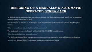
- 1. DESIGNING OF A MANUALLY & AUTOMATIC OPERATED SCREW JACK In this current presentation we are going to discuss the design a screw jack which can be operated manually and automatic as well. Our main goal to achieve is, to design a light weight screw jack which can uplift a Weight upto 3 tonnes. Why we considered it to be lightweight &automatic? The jack could be operated easily without AGE & GENDER consideration. Why the need of adding manual option? The difficulty in providing a power source at each circumstances let us to add the manual option Innovation: Automatic(era) & Internal and External threaded Screw
- 2. SCREW JACK A screw jack is a portable device consisting of a screw mechanism used to raise or lower the load. Principle: The screw jack works is similar to that of an inclined plane. Dc working principle: d.c motor is coupled with the screw jack by gear arrangement. The screw jack shaft‟s rotation depends upon the rotation of D.C motor. The D.Cmotor shaft is connected to the spur gear. If power is given to the D.C motor, it will run so that the spur gear also runs to slow down the speed of the D.C motor. Types of jacks- A hydraulic jack consists of a cylinder and piston mechanism. The movement of the piston rod is used to raise or lower the load. Mechanical jacks can be either hand operated or power driven. Screw jack Mechanical Scissor Jacks Bottle Jacks Hydraulic
- 3. MATERIAL PROPERTIES S. NO. PARTS MATERIAL SPECIFICATION 1) Screw Plain carbon steel 30C8 Syt =400MPa Sut =550MPa d=36mm dc=30mm p=6mm 2) Bearing Chrome stainless steel Syt =300MPa Sut =445MPa ISO104-113352 3) Gear AISI 4340 normalised steel t=12 module=2.5 T=50 4) Lower Frame Hard cast steel 5) Upper Frame Syt =485MPa Sut =275MPa ASTM A27 grade 70
- 4. SCREW Plain carbon steel 30C8 Syt =400MPa Sut =550MPa Single threaded screw(l=p) load=W=3 tonnes=3000*9.8=2940 N Factor of safety=5 Calculation= Syt = 𝑊∗𝑓 𝑝𝑖∗𝑑𝑐2 dc=21.63mm≈30mm(after allowance) let p=6mm d=nominal diameter=dc+p=36mm dm=mean diameter= 𝑑+𝑑𝑐 2 =33mm µ=0.149 ϕ=tan-1µ α=tan-1( 𝑝 𝑝𝑖∗𝑑𝑚 ) α=3.31 deg Self locking ϕ>µ i.e 8.5 deg >3.31deg Torque subjected to screw Mt= 𝑊∗𝑑𝑚∗tan(α+µ) 2 =101431.03 Nmm Shear stress ¢= 𝑝 𝑝𝑖∗𝑑 𝑐 3=19.13Nmm-2 Ϭ(sigma)= 𝑊 𝑝𝑖∗𝑑𝑐2=41.59 Nmm-2 Fs=syt/sigmac=400/41059=9.61
- 5. l=length of screw l=130mm P=effort=250N Mb=250*130=32500 Nmm Sigmab=bending stress associated with bending moment Sigmab=32Mb/(pi*dc 3=12.26 Nmm-2 ζmax= 𝜎 𝑏 2 2 + 𝑇2= 12.2𝜎 2 2 + 19.13 2=20.18Nmm-2 𝑓𝑠 = 0.5∗ 400 ζmax =10 Buckling consideration L=300mm 𝑘 = 𝑇 𝐴 =dc/4=7.5 Slenderness ratio=l/k For given situation l/k=130/7.5=17.33 E=207000Nmm-2 𝑝𝑐𝑟 = 𝑆 𝑔 ∗ 𝜋 4 ∗ 30*30*(1 − 400𝑥 17.33 2 4𝑥 1 4 𝑥𝜋2 𝑥 207000 )=266117.6N Fs=Pcr/W=266117.6/29400=9
- 6. DESIGNING OF NUT For the material of nut ASTM A27 grade 70-40 Sb=permissible bearing pressure Sb=10Nmm-2 z=no. of thread required z= 4∗𝑊 𝜋𝑠 𝑏 𝑑2−𝑑 𝑐 2 =9.45 H=z*p=60mm ζn= 𝑤 𝜋𝑑𝑡𝑍 =8.66Nmm-2 𝑓𝑠 = 𝑠 𝑠𝑦 𝜏 𝑛 =200/8.66=23.08
- 7. SPECIFICATION OF BEARING SPECIFICATION OF GEAR Ball Bearing(axial-loading) Chrome stainless steel Syt =300MPa Sut =445MPa Total height=12.5mm Internal dia=36mm External di=50mm Spur gear-Trapezoidal profile Total no. of teeth=46 Addendum dia=115mm Clearance=1mm Dedundum dia=105mm
- 8. HANDLE Mt=1014314.03Nmm p=effort=250N Mt=p*lh 1014314.03=250*lh lh=405mm 𝜎 𝑏= 32𝑀𝑡 𝜋𝑑ℎ 3 400 5 = 32 × 101431.03 𝜋𝑑ℎ 3 dh=23.46≈24mm
- 9. ANALYSIS OF BEARING Chrome stainless steel Syt =300MPa Sut =445MPa Total height=12.5mm Internal dia=36mm External di=50mm Maximum compressive allowable stress on bearing= 𝑊 Π 4 ∗(502−362) =31.09Nmm-2 fs= 300 31.09 =9.64≈10
- 10. POWER CALCULATION FOR AUTOMATIC Let N be the rpm of the nut containing gear N=15rpm(consider) 𝜔 = 1.57𝑟𝑎𝑑/𝑠𝑒𝑐 P= 𝜔*Mt P=1.57*101431.03*10-3watt P=159.2watt Neglecting collar friction as well as moment associated with it
- 11. PARTSOF THE LIFTINGJACKIN EXPLODEDVIEW
- 15. EQUIVALENTSTRAIN
- 16. UNDER THE GUIDANCE OF DR KALYAN KUMAR SINGH GROUP MEMBERS • Abhishek Kumar 15JE001459 • Akshay Mandwale 15JE000968 • Sachin Kumar 15JE001463 • K Bharat Kumar 15JE001160 • Raghvendra Singh 15JE001431