
Recommended
More Related Content
What's hot
What's hot (10)
Similar to An Analysis of Ideal Atwood Machine
Similar to An Analysis of Ideal Atwood Machine (20)
Recently uploaded
Recently uploaded (20)
An Analysis of Ideal Atwood Machine
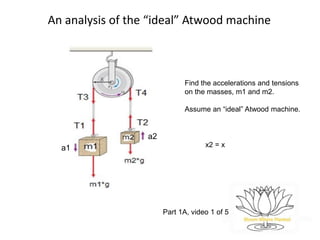
- 1. An analysis of the “ideal” Atwood machine Find the accelerations and tensions on the masses, m1 and m2. Assume an “ideal” Atwood machine. a1 a2 Part 1A, video 1 of 5 x2 = x
- 2. An analysis of the “ideal” Atwood machine Agenda: Solve for the acceleration and tension in the ideal Atwood machine in a non-standard way. Rationale: Too many online and textbook solutions “hand wave” over details involved in the analysis. These omissions/oversimplifications prevent a deeper understanding of a rather sophisticated problem. Typically, there are 2 sources of (“hand-waved”) simplifications: 1. Failure to explain the implications behind the “ideal” assumptions. 2. Failure to explain sign conventions and their interpretation. Prerequisites: 1. Familiarity with (vector) forces and their relation to acceleration; namely Newton’s 2nd law. 2. Familiarity with the definition of torque (again as a vector quantity). Recommendation: Stop video and read each slide and then continue along while the slides are cleared.
- 3. An analysis of the “ideal” Atwood machine Agenda: Solve for the acceleration and tension in the ideal Atwood's machine. In part 1 (videos 1 & 2): Identify the 3 “hidden” assumptions that are needed to understand the physics of the ideal Atwood machine. 1. Inexstensible string/chord 2. Massless & frictionless pulley 3. Massless or “light” string/chord In part 2 (video 3): We’ll work through the algebra and find solutions for the accelerations and tensions involved and then check if our answers make sense. The goal here is to understand the physics (dynamics) behind the motion. In part 3 (videos 4 & 5): Review other approaches to solution with the goal of understanding how to interpret “sign convention.” Together, assumptions 1 & 3 are what make an “ideal” chord. Assumptions 2 are what make an “ideal” pulley.
- 4. 4 Typical problem From “Physics for Scientists and Engineers” by Raymond Serway, 3rd ed. Chapter 5, Example 5.4 “Atwood's Machine” “When two unequal masses are hung vertically over a light, frictionless pulley, as in the figure, the arrangement is called Atwood's machine. The device is sometimes used to determine the acceleration of gravity. Determine the acceleration of the two masses and the tension of the string.”
- 5. 5 Setting up the solution From Serway's free body diagram, we see m2 > m1. In part 3 (3rd video), we'll solve this problem. Here, we're changing the problem so that m1 > m2. Free body diagram w/ “assumed” sign convention: T1 T2 m1 W1 = m1*g m2 W2 = m2*g Given m1 > m2. a1 a2 up: “+” down: “ - ” From free body diagram write down equations using Newton's 2nd law: T1 – m1 * g = - m1 * a1 (1a) T2 – m2 * g = m2 * a2 (1b) * We notice that we have 4 unknowns (T1, a1, T2, a2) and only 2 equations. m1 and m2 are “givens.”
- 6. 6 Use the “hidden” assumptions to reduce the number of unknowns Assumption 1: The string or chord is “inextensible.” In the Serway problem, this condition is not mentioned. Very typical. However, it's implication appears in the free body diagram. When the string is “inextensible” (= “doesn't stretch”), ||a1|| = ||a2||. X1 = X x2 = x 1. Pull on mass 1 a distance X. Assume both masses start at position 0 and are initially at rest: {x(0) = 0 ; v(0) = 0} . 2. If the string doesn't stretch, both masses move the same distance “x.” X1 = X2 = X. 3. Since this happens in the same time for both masses, velocity (xdot) and acceleration are the same (Xdouble dot). Since X1 = X2 = X (for same ∆t), then v1 = v2 = v & ||a1|| = ||a2|| = a. We can substitute this into our earlier eqns. T1 – m1 * g = - m1 * a (1a) T2 – m2 * g = m2 * a (1b) ˙x≡ v= Δ x Δ t ; ¨x≡ a= Δv Δt Now, we have 2 eqns. & 3 unknowns. 0 x x 0 3. (cont.): 𝑥 − 0 𝑡 − 0 = 𝑥 𝑡 = ¨x≡ a= Δv Δt v − 0 𝑡 − 0 = 𝑣 𝑡 = ˙x≡ v= Δ x Δ t
- 7. 7 Use the “hidden” assumptions to reduce the number of unknowns Next, our goal is to show that the tension in the string is uniform (the same) everywhere on the string. That is, T1 = T2 = T3 = T4 (= “T”). We'll need assumptions 2 to show T3 = T4; and we'll need assumption 3 to show T1 = T3 & T4 = T2. Fig. 1 Fig. 1 introduces 2 new forces, T3 & T4. As before, T1 is the tension force of the string on m1. As before, T2 is the tension force of the string on m2. T3 is the tension force of the string on the pulley; T3 causes a “CCW” rotation. T4 is the tension force of the string on the pulley; T4 causes a “CW” rotation. M is the mass of the pulley (M = 0) and R is its radius. Note: These tension forces act on different objects. T3 & T4 act on the pulley. T1 acts on m1 and T2 acts on m2. M R
- 8. An analysis of the “ideal” Atwood machine Find the accelerations and tensions on the masses, m1 and m2. Assume an “ideal” Atwood machine. a1 a2 Part 1B, video 2 of 5
- 9. 9 Use the “hidden” assumptions to reduce the number of unknowns Our goal is to show that the tension in the string is uniform (the same) everywhere on the string. That is, T1 = T2 = T3 = T4 (= “T”). Using assumptions 2 (massless and frictionless pulley) we’ll show T3 = T4. Using assumption 3 (massless string), we’ll show ||T1|| = ||T3|| and ||T2|| = ||T4||. Before we show that our assumptions will result in uniform tension, lets take a look at why this assumption is non-trivial or perhaps not so obvious. To do this, we'll consider the case of a very heavy pulley with large friction. This pulley is created by putting a finger on the string to prevent the pulley from rotating... Our finger force is represented by the large arrow in Fig. 2. When the pulley is fixed and cannot rotate, T1 and T2 are different: T1 = m1*g > T2 = m2*g because m1 > m2 (given). Fig. 2 In this 'non-ideal' case, T1 > T2. So it's not always correct in assuming the tension is uniform everywhere.
- 10. 10 Use the “hidden” assumptions to reduce the number of unknowns Assumption 2: The pulley is “massless and frictionless.” Massless and frictionless refer to different conditions: Massless (or “light”) pulleys have no “moment of inertia.” Frictionless pulleys do not suffer any friction losses; all energy is used to accelerate masses up and down. Newton's 2nd law (F= m*a) has a rotational analog: Torque net = Σtorques = I * α, where I is the “moment of inertia” and α (alpha) is rotational acceleration. I is the rotational analog of mass; alpha is the rotational acceleration. For a disk I = ½ * M * R^2, where M is the mass of the disk (pulley) and R is its radius. If M = 0, then I = 0. In order for a disk to rotate “CCW” (as assumed), T3 > T4 (for a pulley with mass). If no mass, then (as we’ll show) T3 = T4.
- 11. 11 Use the “hidden” assumptions to reduce the number of unknowns Assumption 2: The pulley is “massless and frictionless.” Torque Ͳ is a vector quantity (force X lever arm). ||Ͳ|| = T * R * sin(θ) . For our pulley , θ = 90○. Using Newton's 2nd law for rotation, we can write: Torque net = ΣTorques = Ͳ3 - Ͳ4 = I * α, where sign convention is CCW is “+” & CW “ - .” +T3 * R * sin(90○ ) – T4 * R * sin(90○) = I * α ; So, +T3 * R – T4 * R = I * α Applying assumption 2 (M = 0), we find: +T3 * R – T4 * R = 0 * α = 0; T3*R = T4 *R Therefore, T3 = T4. That is, the massless pulley assumption tells us the tensions on both sides of the pulley are the same. “Frictionless” just tells us that none of the gravitational energy (primer mover causing the rotation) is used to rotate the pulley. Problem solving hint: When pulley diagram is simple (no radius or mass given), rotation can usually be ignored. This is the “ideal” Atwood machine. Now, let's find the relationship between T1 and T3...
- 12. 12 Use the “hidden” assumptions to reduce the number of unknowns Assumption 3: The string or chord is “light” or massless. As before , let's first take a look at the opposite case, the “heavy” string and see its implications. (We'll see that the self weight of the string contributes to the tension.) Ms * g T6 The free body diagram for a small piece of “heavy” attached to a ceiling... Using Newton's 2nd law, our free body diagram, & sign convention, we can write: T5 – T6 – Ms *g = Ms * a. T6 = 0, there is nothing pulling on the bottom. a = 0 since the string is not moving (static case). Substituting into our equation we find: T5 – 0 – Ms * g = 0 => T5 = Ms*g If the string is uniform, the tension will change gradually from 0 on the bottom to T5 = Ms * g on the top. So here we see a situation where tension is not constant, but changes gradually. up: + down: - T5 a
- 13. 13 Use the “hidden” assumptions to reduce the number of unknowns Assumption 3: The string or chord is “light” or massless. In the Serway problem, the condition of string is not given explicitly. The implication of a light or massless string is that the tension is the same at the top and bottom of the string. That is, ||T1|| = ||T3|| and ||T2|| = ||T4||. T7 Ms * gT8 Let's take a look at the free body diagram for a small section of string somewhere in the middle of the string. Using Newton's 2nd law, our free body diagram, & sign convention, we can write: T7 – T8 – Ms *g = Ms * a. Since Ms = 0, we have T7 – T8 = 0 => T7 = T8 . By repeating this argument (induction), we establish that tension is uniform for each of the vertical segments of the pulley. The self weight of the rope does not add to the tension. That is, T1 = T3 and T2 = T4. up: + down: - a
- 14. 14 Use the “hidden” assumptions to reduce the number of unknowns Assumptions 2: The pulley is massless and frictionless (given). Assumption 3: The string or chord is “light” or massless. From assumptions 2, we established: T3 = T4. (3) From assumption 3, we established ||T1|| = ||T3|| and ||T2|| = ||T4|| (4) Combining these results, we find: ||T1|| = ||T3|| = ||T4|| = ||T2|| = T We can substitute T2 = T1 = T into our earlier eqns.: T – m1 * g = - m1 * a (1a) T - m2 * g = m2 * a (1b) Now we can solve the system of eqns.
- 15. An analysis of the “ideal” Atwood machine Find the accelerations and tensions on the masses, m1 and m2. Assume an “ideal” Atwood machine. a1 a2 Part 2, video 3 of 5
- 16. 16 Part 2: Solve the system of equations; check solution In the last 2 videos, we showed that: An inextensible string tells us that the masses will accelerate at the same rate. ||a1|| = ||a2|| = a A massless pulley tells us that the tension on both sides of the pulley are the same. T3 = T4 A massless chord tells us that the tension is uniform up and down the chord. ||T3|| = ||T1|| & ||T4|| = ||T2|| T – m1 * g = - m1 * a (1a) T - m2 * g = m2 * a (1b) Now we can solve the system of eqns. ╚>
- 17. 17 Solve the system of 2 eqns. for the 2 unknowns; find a. Recall, that we now have (through our assumptions now revealed): T – m1 * g = - m1 * a (1a) T - m2 * g = m2 * a (1b) Solve for a with usual algebra: -T + m1*g = m1 * a (1a) multipy both sides by -1 T - m2*g = m2 * a (1b) no change 0 + m1*g – m2*g = m1*a + m2*a (2) add (1a) to (1b) (m1 – m2) *g = (m1 + m2) a (2) factor g on left and a on right hand side So, a = (m1 – m2) * g (2) divide by (m1 + m2) (m1 + m2) Let's check special cases to see if answer makes sense: Case 1: m1 = m2, a = 0 Case 2: m1 >> m2 (m1 much larger than m2) No movement! So, m1 + m2 ≈ m1; m1 – m2 ≈ m1 Static equilibrium a = m1/m1 * g = g Free fall! +
- 18. 18 Solve the system of 2 eqns. for the 2 unknowns; find T. Subsitute “a” in eqn. 1a. Solve for T.
- 19. 19 Does the equation for T make sense? T T m1 m1*g m2 m2*g Given m1 > m2. a a up: “+” down: “ - ” In order for m1 to move down (fall), & In order for m2 to move up, T < m1 *g T > m2 * g To make intuition easier, let's further assume m1 >> m2. So, m1 + m2 ≈ m1 as before. This means that T = 2 ((m1*m2) / (m1 + m2) ) g < m1 g & T = 2(m1 * m2)/(m1 + m2) g > m2*g 2*(m1*m2 / m1) < m1*g 2 ((m1*m2) / m1) g > m2*g m1 > 2*m2 2 > 1 T is consistent w/ conditions necessary for masses to move.
- 20. An analysis of the “ideal” Atwood machine Find the accelerations and tensions on the masses, m1 and m2. Assume an “ideal” Atwood machine. a1 a2 Part 3A, video 4 of 5
- 21. 21 Part 3: Review other solutions to ideal Atwood machine along with sign conventions Now, m2 > m1 (given). Notice how roles of m1 and m2 are reversed; a neg sign has been added. Both solutions are correct. Our problem assumed “a,” the acceleration, was in opposite direction.
- 22. 22 Part 3: Sign of solution is always relative to “assumptions” of problem (sign convention & assumed directions) In Serway's solution we found that: a = (m2 – m1) * g , (m1 + m2) where it was given that m2 > m1. Also, the sign convention was that up was “+” and down was “-.” This was the same sign convention we used earlier. Now, what if we inputted m1 = 5 Kg and m2 = 3 Kg? (This is the problem that we solved in Part 1.) The answer would give us a negative acceleration according to the solution in blue above. How to interpret? A solution that comes out negative simply means that the direction of the acceleration (or quantity) is opposite to what was assumed in the problem. And the interpretation is consistent with the sign convention.
- 23. 23 Another “free body diagram” approach Several online videos use different sign conventions for each of the free body diagrams. (In this approach the direction of “a” is always assumed positive.) T T m1 m1*g m2 m2*g Given m1 > m2. a a up: “+” down: “ - ” For m1, we find: - T + m1* g = m1 * a For m2, we find: T - m2 *g = m2 * a Solving for a, we find a = (m1 – m2) * g . a is positive (m1 > m2), so (m1 + m2) assumed directions are correct. up: “ - “ down: “+”
- 24. 24 Another “free body diagram” approach Other online videos, use a sign convention where positive signs are written to indicate the direction of rotation. T T m1 m1*g m2 m2*g Given m1 > m2. a a up: “+” down: “ - ” up: “ - “ down: “+” CCW “+” + + + + + + The approaches where different sign conventions are used fpr each FBD (the direction of acceleration is assumed to be positive) comes from the idea that rotation in the counter- clockwise (CCW) direction is positive. Other videos will communicated this concept by putting “+” signs in the direction of motion. These 3 approaches are the same sign convention.
- 25. An analysis of the “ideal” Atwood machine Find the accelerations and tensions on the masses, m1 and m2. Assume an “ideal” Atwood machine. a1 a2 Part 3B, video 4 of 5
- 26. 26 The “systems” approach The system is now defined as everything within the dotted line. The external forces acting on the system are m1 * g and m2 * g. The “T's” are internal forces and do NOT contribute to acceleration of system. In fact, they cancel as do all internal force (pairs). Newton's 2nd law, Fnet = Σ Fsys = m * a: - m1 * g + m2 * g = (m1 + m2) * (- a). Solving for a, we find: a = (m1 – m2) * g as before. Because “a” is positive, we know assumed (m1 + m2) direction (to the “left” or “CCW”) is correct. Given m1 > m2. aa m2m1 TT sign convention: Left or CCW is “ - “ m2 *gm1 *g Assumed direction of a Is to left. m1 *g m2 *g CCW
- 27. 27 The “systems” approach (different assumption for a) The system is now defined as everything within the dotted line. The external forces acting on the system are m1 * g and m2 * g. The “T's” are internal forces and do NOT contribute to acceleration of system. In fact, they cancel as do all internal force (pairs). Newton's 2nd law, Fnet = Σ Fext = m * a: - m1 * g + m2 * g = (m1 + m2) * a. Solving for a, we find: a = (m2 – m1) * g -the same answer as Serway. But, “a” is negative under our (m1 + m2) given (m1 > m2). So direction is the left, opposite of our assumption. Given m1 > m2. But assume a is to right: a m2m1 TT Same sign convention: left/CCW is “ - “ m2 *gm1 *g Assumed direction of a Is to right.