
Recommended
More Related Content
What's hot
What's hot (20)
Similar to Sheet metal Fundamentals
Similar to Sheet metal Fundamentals (20)
Recently uploaded
Recently uploaded (20)
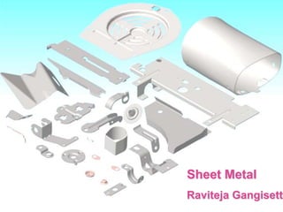
Sheet metal Fundamentals
- 2. What is Sheet Metal? Sheet metal are generally sheets less than 6 mm. Sheet metal is produced by reducing the thickness of a long work piece by compressive forces applied through a set of rolls. This process is known as rolling. Introduction
- 3. In today’s practical and cost conscious world, Sheet metal parts have already replaced many expensive Cast, forged and machined products. The reason is obviously the relative cheapness of stamped, mass produced parts as well as greater control of their technical and aesthetic parameters. Example 1: Designing a sheet metal part as a replacement for a spot welded assembly. (1) (2) The figure 1 shows a conventional product having parts attached to it by spot welding while figure 2 shows a modification of the product through sheet metal operations. Introduction
- 4. Example 2: Designing a sheet metal part as a replacement for a machined part. (1) (2) • The figure 1 shows a machined parts while figure 2 shows sheet metal parts replaced functionally. • Two-part clamping hub with 6 counter bores for carrier bars with threaded stems. Introduction
- 5. Sheet metal is widely used for numerous industrial and non-industrial applications including: Aircraft: Wings, body panels, trim parts, etc. Automotive : Automotive body panels, bumpers, doors, chassis, trim parts, brackets etc. Construction: Sheet metal is used for roofing, home building and structural applications. Other applications: Sheet metal is used for manufacturing appliances, food and beverage containers, boilers, ships, kitchen equipment and office equipment etc. Applications
- 6. Advantage of Sheet Metal Parts: • Good strength • Good Dimensional accuracy • Good surface finish • Relatively low cost • Low weight Advantage
- 7. Suitability of Materials Most of the ductile wrought metals are suitable for sheet metal working. Formability ratings of materials: Aluminum, copper and their alloys: Excellent Mild steel and stainless steel: Fair to excellent Nickel and magnesium: Fair to good Aluminum alloys Brass, low leaded Hot rolled steel Low carbon steel Austenitic Stainless steel Cold rolled steel High strength-low alloy steel Titanium and Titanium alloys Beryllium copper Cold rolled aluminum- killed steel Low alloy steel Zinc alloys Some of the material suitable for sheet metal working are: Materials
- 8. •Aluminum-Zinc Alloy •Aluminum-Zinc Coated Steel •Cold Rolled Steel •Galvanized Steel Types Raw Sheet metal Material
- 9. Aluminum-Zinc Coated Steel (Galfan) : Galfan is a zinc alloy coating that consists of 95% zinc and 5 % aluminum. This alloy coating provides superior corrosion protection, extraordinary formability and draw-ability, excellent paint-ability and good weld-ability. Cold Rolled Steel: Hot-rolled coils decaled by pickling are put on the cold rolling mill where they are rolled to a specified thickness. After being rolled on a cold strip mill, coil-rolled coils undergo a finishing process to meet proper hardness and to prevent stretcher strains. Galvanized Steel: The base coil is pickled and cold-rolled then processed through continuous galvanizing lines. The finished product has a smooth finish with uniform zinc coating, excellent durability and workability. Material
- 10. Advantages Good Corrosion Resistance Excellent Paintability Easy Weldability High Temperature Use High ductility and strength Excellent high and low temperature properties Non-magnetic Easy to handle & Install Aesthetic surface finish Life-cycle costing benefits Disadvantages Spring back may be significant. Non-uniform thickness may happen. Wrinkling, earing, tearing. GALVANISED STEEL Material
- 11. Theoretical sheet metal thickness gauges: Non ferrous gauges (Aluminum) are not the same as ferrous gauges (Steel & stainless) It is common practice to specify the aluminum simply in the decimal thickness. For example, “MATERIAL : 0.100 5052-H32 ALUMINUM”. Steel and Stainless steel are frequently specified by gauge and decimal thickness. For example, “MATERIAL: 16 GA (.059) COLD ROLL STEEL”. There are other gauges than those listed in this table, but these are the ones that are commonly available. Gauges
- 12. BEND RADIUS GUIDE LINES ARE AS FOLLOWS: For most materials, the minimum inner radius should be at least 1 material thickness. Bending using tight radiuses often results in burrs and fractures on the outside of the bends. These can be eliminated by using larger bend radiuses and by providing relief notches at the edges on the bend line. Bend relief notches should be 2 times the thickness in width (min 1.5mm/0.060 in) and radius + thickness in length. Bend radius should be kept same for all radiuses to minimize the set up changes. Bend relief eliminates tearing W= 2 X thickness L= Bend Radius + Thickness No Bend relief causes tearing Bend Radius Design
- 13. Distance between two cuts or punches & Distance between part edge and cut or punch: For Hole Dia <10T For Hole Dia <5T 1.5T 2T For L <10T For L >10T 2T 4T Guidelines for Hole and slot spacing according to size. Design
- 14. The minimum flange width should be at least 4 times the stock thickness plus the bending radius. Violating this rule could cause distortions in the part or damage to tooling or operator due to slippage. On bends, the short leg (inside length) should be a minimum of 2.5 x stock thickness + radius. Flange width: Bend height of walls: Design
- 15. Distance between bend and cut or punch: When a bend is made too close to a hole, the hole may become deformed. Figure A shows a hole that has become teardrop shaped because of this problem. To save the cost of punching or drilling in a secondary operation the following formulas can be used to calculate the minimum distance required. For a hole Dia <1, minimum distance =2T+Bend radius For a slot width or Hole Dia >1, minimum distance =2.5T+Bend radius Design
- 16. SHEET METAL MANUFACTURING ARE CLASSIFIED INTO TWO GROUPS: CUTTING NON CUTTING CUTTING: PUNCHING BLANKING PIERCING PARTING OFF NOTCHING SLITTING LANCING BENDING: ANGLE BENDING CURLING PLUNGING DRAWING: BULGING SQUEEZING: COINING EMBOSSING FLATTENING OR PLANISHING Manufacturing
- 17. DIE :- The word DIE has several definitions. a. A complete production tool, the purpose of which is to produce the piece parts consistently to required specifications. b. The female part of a complete die. A punch is a male member of a press tool. It is usually the upper member and is clamped to the top bolster (but it is depends on the requirement.) Punches are used for Piercing, Blanking, Bending, Embossing, forming, etc.. PUNCH :- SHEARING PROCESS Manufacturing
- 18. Shearing action between two sharp edges • Punch: upper cutting edge • Die: lower cutting edge Shearing Process-Steps • Plastic deformation • Penetration • Fracture A cut edge has Roll-over (about 5% of the thickness), Shear (about 30% of the thickness, Break (the remaining % of the thickness) and Burr, potentially up to 10% of material. Manufacturing
- 19. Plastic Deformation - Punch engages the sheet metal - Pulls the material downward - Slightly drawing the material into the clearance - Creates a Rollover Penetration - Punch continues to travel - Shear the upper portion of the material - Material becomes locked between the punch and the die - Creates a burnished area Fracture - Punch travel further - Material is fractured or separated completely - Creates Burr Manufacturing
- 20. Rollover • Rounded corner Burnish • Smooth surface Fractured Zone • Rough surface Burr • Sharp corner Sheared Edges A cut edge has Roll-over (about 5% of the thickness), Shear (about 30% of the thickness, Break (the remaining % of the thickness) and Burr, potentially up to 10% of material. Manufacturing
- 21. Clearance (C) Distance (Gap) between punch and die 4%-8% of sheet thickness Small Clearance double burnishing large cutting force Large Clearance Sheet becomes pinched excessive burr Manufacturing
- 22. Manufacturing
- 23. Cutting Forces (F) • F = S * t * L – S - shear strength – t - thickness – L - length of cutting edge • F = 0.7TS * t *L – TS - Ultimate tensile strength • Max F is used to determine press for operation Manufacturing
- 24. BLANKING The actual cutting or the blank of component is done by the cutting edge or the die opening. There fore die opening determines the die of the blank of component OR -Cutting along an outline in a single step and produce required part Is called PIECE PART. Cutting of flat metal sheet or strip stock into the required size and shape Blanking is sub divided into two groups 1. Conventional blanking. 2. Fine blanking. Manufacturing
- 25. Process Characteristics Shears the work piece from the parent stock as the punch enters the die. Produces burnished and sheared section on the cut edge Produces burred edges Quality is controlled by the punch and die clearance CONVENTIONAL BLANKING Conventional blanking is a shearing process in which a work piece is separated from the parent material when the punch enters the die. Manufacturing
- 26. Process Characteristics Die clearance is approximately 1% of stock thickness. Produces clean, smooth edges. Hole sizes and spacing can equal stock thickness. Material thicknesses of 0.0006 in. to 0.60 in. for steel, brass, aluminum, etc. Produces minimal surface distortion Punch does not enter die Uses a V-ring that is embedded in the stock to control fracture FINE BLANKING Fine blanking is a controlled shearing process in which a tightly clamped work piece is forced through a fixed die opening to produce accurate work pieces with a fine finish and straight edges. A V-shaped ring around the perimeter of the work piece presses into the stock to control material flow. Manufacturing
- 27. PUNCHING The actual cutting or the opening in stock material is does by the punch. There fore size or the punched opening determined by the punch. Cutting openings such as holes and slots in sheet stock, strip material, or a part Or -This operation is Same as blanking but produces SCRAP (SLUG) PART REQUIRED BLANK SCRAP Manufacturing
- 28. Process Characteristics Is the most economical method of making holes in sheet or strip metal for medium to high production Can produce various shaped holes Punches and dies are normally made of conventional tool steel or carbides Produces a burnished area, roll-over, and die break on the sidewall of the resulting hole PUNCHING Punching is a shearing process in which a scrap or slug is separated from the work piece when the punch enter the die. The sidewall of the resulting hole displays a burnished area, rollover, and die break. Manufacturing
- 29. PARTING OFF The parting is the operation of cutting a sheet metal in two parts. Unlike cutting of potation, some quality of scrap is removed to make the work piece in two parts. Manufacturing
- 30. Process Characteristics Removes metal from the edges of the work piece Can produce different angled notches by adjusting the position of the work piece Directly produces re-entrant cuts not possible by shearing Can facilitate bending or drawing to achieve final geometry NOTCHING Notching is a shearing operation by which metal scrap is removed from the outside edge of a work piece by multiple shear blades set at right angles to each other. Notching can be used to provide relief from wrinkling before drawing or forging. It is a manually operated, low production process. Manufacturing
- 31. Process Characteristics Is limited to relatively thin materials (0.001 to 0.125 in.) Burrs are normally present to some extent on slit edges May be used on ferrous and nonferrous metals, plastics, and paper Is a high production, width-control process SLITTING Slitting is a shearing process used to cut wide coils of material into several coils of narrower width as the material passes lengthwise through circular blades. Manufacturing
- 32. Process Characteristics Cuts a portion of the periphery of the hole, and the remainder is bent to the desired shape Removes no metal from the work piece Can use a single cut to facilitate the making of special features LANCING Lancing is a combined shearing and bending operation where a portion of the periphery of a hole is cut into the work piece and the remainder is bent to the desired shape. No material is removed from the work piece by this process. Manufacturing
- 33. Perforating • punching of a pattern Trimming, Shaving • operations to clean up and smooth out edges Manufacturing
- 34. BENDING is usually defined as "the plastic deformation of a sheet metal along a straight line". Air Bending is done with the punch touching the work piece and the work piece, not bottoming in the lower cavity. This is called air bending. As the punch is released, the work piece ends up with less bend than that on the punch (greater included angle). This is called SPRING BACK. The amount of spring back depends on the material, thickness, grain and temper. The spring back usually ranges from 5 to 10 degrees. Usually the same angle is used in both the punch and the die to minimize setup time. The inner radius of the bend is the same as the radius on the punch. Manufacturing
- 35. Spring back: Materials will have a finite modulus of elasticity, plastic deformation is followed by elastic recovery upon removal of the load. In bending, the recovery is known as spring back Elastic recovery: SB=(A’-A’b)/(A’b) A’b=included angle of the bending tool, A’=included angle of the sheet metal part Manufacturing
- 36. Spring back Compensating Methods Over bending : Punch and Die angle is less than the part angle Die angle = Part angle + Spring back <90 Manufacturing
- 37. Spring back Compensating Methods Bottoming: Clearance between the punch and die surface is less than the blank thickness. As a result, the material yields slightly and reduce the spring back. Bottom bending requires considerably more force (about 50%~60% more) Manufacturing
- 38. Spring back Compensating Methods Coining: Compressive stress is applied to bending region to increase the amount of plastic deformation. This reduces the amount of spring back. Manufacturing
- 39. Bending Methods V-Bending: Clearance between punch and die is constant U-Bending: Two parallel bending axes are produced in the same operation. Edge Bending: One edge of the sheet is bent to 90 while the other end is restrained Manufacturing
- 40. BENDABILITY (the smallest achievable bending radius without failure) of materials is improved by heating or application of hydrostatic pressure. Cracking can also be eliminated by inducing compression in the bending direction. Bendability of narrow sheet is higher than wide sheets. Narrow sheets are observed to crack usually at the edges, while wide sheets tend to crack at the center. Manufacturing
- 41. Estimating the minimum bend radius: Metal can only be bent to a certain angle before cracks form at the bend and, ultimately, the work piece breaks. To predict the smallest achievable radius that a sheet can be bent to, the following equation can be used: Where t : thickness Rmin : minimum bend radius r : reduction in area in a tensile test for a given material (%) Ao and Af are the original and final (fracture) Manufacturing
- 43. Here are some examples of parts manufactured by bending. Manufacturing
- 44. CURLING Curling is a operation of forming the edges of a component into a roll or a curl by bending the sheet metal in order to strengthen the edges and to provide smoothness to its surface. Manufacturing
- 45. PLUNGING Plunging is the operation of bending a sheet metal to the desired shape for accommodating a screw or a rod through plunged hole. The plate is first pierced at the required position and then the plunging punch is pressed in the hole. This causes displacement of the metal in the die cavity and The shape of the plunged hole depends on the shape of the punch. Manufacturing
- 46. Photograph showing the bulged shapes in the three stages in repeated bulging of copper tubes with interstate annealing. From left to right, 1st stage, 2nd stage and the 3rd stage, respectively. BULGE FORMING BY HYDRAULIC PRESSURE Assembly of the tooling for bulging. BULGING Manufacturing
- 47. Drawing leads to wrinkling and puckering at the edge where the sheet metal is clamped. This is usually removed by a separate trimming operation. Design Considerations: Round shapes (cylinders) are easiest to draw. Square shapes can also be drawn If the inside and outside radiuses are at least 6 X stock thickness. Other Shapes can be produced at the cost of complexity of tooling and part costs. Manufacturing
- 48. Making A Cup shape part Blanks Many shapes and sizes Die Cavity Shape in which the metal will take on Punch Pushes metal into die cavity Blank Holder A device to hold the blank Manufacturing
- 49. In drawing , a blank of sheet metal is restrained at the edges, and the middle Section is forced by a punch into a die to stretch the metal into a cup shaped drawn Part. This drawn part can be circular, rectangular or just about any cross-section. DRAWING Manufacturing
- 51. DEEP DRAWING Part formed deeper than the diameter (DR > 2.0) Manufacturing
- 52. DRAWING OPERATION FOR AUTO MOBILE PANELS Drawing operation of the auto mobile panels is different than general drawing operation. In this operation component may have any complicated profile, not like as simple Circular or as simple rectangular shapes. Drawn component Finished components LH RH Manufacturing
- 53. DEFECTS IN DRAWING Wrinkling Splits/Cracks Earing Surface Scratches Earing Wrinkles Manufacturing
- 55. If the thickness of the sheet it enters to the die is more than the clearance between die and punch the thickness has to be reduced to meet the precise dimensions, this effect is called a ironing Smaller clearance greater the amount of ironing IRONING Manufacturing
- 56. Manufacturing
- 57. DIES:- Simple - Single operation with a single stroke Compound - Two operations with a single stroke Combination - Two operations at two stations Progressive - Two or more operations at two or more stations with each press stroke, creates what is called a strip development Manufacturing
- 58. SIMPLE DIE:- Single operations with a single stroke Manufacturing
- 59. COMPOUND DIE:- Two operations with a single stroke Manufacturing
- 60. PROGRESSIVE DIE:- Two or more workstations One or more operations under each working station. Strip moves from first to last station to produce complete components. Manufacturing
- 61. Tool pictures of some of the progressive dies used in Appliance and Auto industries Large pierce die with multiple hand operated gags for tractor trailer side 11 Station pierce, pilot, lance, bead and blank out progressive die Thirteen (13) station large 2' X 4' Progressive Die to produce shelf brackets Manufacturing
- 62. Tool pictures of some of the progressive dies used in Appliance and Auto industries Manufacturing
- 63. CHARACTERISTICS OF PROGRESSIVE DIES Utilization of multiple cutting and/or forming operations. Suitable for producing small parts at a rapid rate. Necessity to invest in expensive die sets. Ability to save time and money by combining forming operations. Capability to maintain close tolerances. Manufacturing
- 64. Advantages of PROGRESSIVE DIES: Shorter operation time. Less material handling. Higher accuracy. Disadvantages of PROGRESSIVE DIES: Higher degree of skill required for manufacturing. Higher tool cost. Serious maintenance problems. Higher material wastage. Manufacturing
- 65. PRESSES: The presses can be categorized to two types: Mechanical presses:- Eccentric,crankshaft,knuckle joint Hydraulic presses:- Driven by a piston/cylinder system Manufacturing
- 66. MECHANICAL PRESSES Mechanical presses has a mechanical flywheel to store the energy, transfer it to the punch and to the workpiece. They range in size from 20 tons up to 6000 tons. Strokes range from 5 to 500 mm (0.2 to 20 in) and speeds from 20 to 1500 strokes per minute. Mechanical presses are well suited for high-speed blanking, drawing and for making precision parts. Manufacturing
- 67. HYDRAULIC PRESSES: Hydraulic Presses use hydraulics to deliver a controlled force. Tonnage can vary from 20 tons to a 10,000 tons. Strokes can vary from 10 mm to 800 mm (0.4 to 32 in). Hydraulic presses can deliver the full power at any point in the stroke; variable tonnage with overload protection; and adjustable stroke and speed. Hydraulic presses are suitable for deep-drawing, compound die action as in blanking with forming or coining, low speed high tonnage blanking, and force type of forming rather than displacement type of forming. Manufacturing
- 68. Dies and Presses Mechanical C-Frame Hydraulic C-Frame Mechanical Open Frame Manufacturing