2. Objectives
• Use remote sensing software to detect
earthquake (April,2015) and aftershocks impact
in the core of Kathmandu city, Nepal.
• Determine location of earthquake affected areas
by comparing pre and post earthquake images.
• Compare the location of earthquake affected
areas to the NGA Nepal earthquake damage
assessment points.
• Extract vegetation and man made features by
using NDVI.
2
3. Data
• Landsat 8 OLI/TIRS Images of Kathmandu city,
Nepal taken on path 141, row 41 on dates
29 March, 2015 (Pre earthquake)
1 June, 2015 (Post earthquake)
• Shapefiles- Nepal, Kathmandu
• NGA Nepal Earthquake Damage Assessment
Points Shapefile
• Images are of 30m spatial resolution.
• The projected Coordinate System used for
Kathmandu city “WGS_1984_UTM_ Zone_45N”.
3
4. Tools
• Envi (Environment for Visualizing Images)
Images were calibrated by using “Radiometric
Calibration Tool”.
Subset of Images are made to extract area of interest
by using “Subset Data from ROIs”
Vegetation and man made features are extracted by
using “NDVI”.
The difference between the images are shown by using
“Image Change Detection Workflow”
• ArcGIS 10
• Google Maps
4
5. 5
Pre Earthquake Image of
Kathmandu city, Nepal
(29th March, 2015)
Post Earthquake Image of
Kathmandu city, Nepal
(1st June, 2015)
Pre Earthquake Image
of central core of
Kathmandu city
(Area of Interest)
Post Earthquake Image
of central core of
Kathmandu city
(Area of Interest)
Pre Earthquake NDVI
resulted Image (extracted
vegetation & man made
features)
Post Earthquake NDVI
resulted Image (extracted
vegetation & man made
features)
Difference between the images
(Blue Decrease Areas represent location of earthquake affected areas)
Calibrated and subset both Images using ROI
Used NDVI on both images
Used Image change Detection workflow
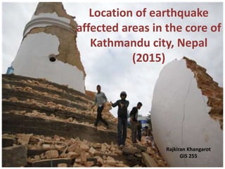
6. Study area- City Core of Kathmandu,
Nepal
• Kathmandu city core is
the most populated
area.
• The city core was highly
affected by earthquake.
• The study area is about
23 mile².Google Maps
6
7. Pre and Post Earthquake Imagery
29 March, 2015 1 June, 2015
7
8. Normalized Difference Vegetation
Index (NDVI)
• This index is a measure of
healthy, green vegetation.
• Varies between -1.0 and
+1.0
• Light areas represent
regions of high
vegetation.
• Dark areas show regions
of low vegetation.
8
10. Image Change Detection Workflow
• The Image Change
workflow compares
two images of the
same geographic
extent, taken at
different times, and
it identifies
differences between
them.
• The difference can
be computed on a
specified input band
or on a feature
index, and can
optionally apply
thresholding.
10
15. Conclusions
• Remote Sensing is a complex and highly involved
process.
• The result of Image Change Detection (area decrease)
did not match with NGA- Nepal Earthquake Damage
Assessment Points.
• The decrease areas are not only influenced by the
earthquake but also affected by other factors
(Phenology, uncorrected atmospheric or sensor effects,
vertical or horizontal land movement).
• Area increased after earthquake is due to increase in
vegetation cover (Seasonality effect) which shows
vegetation plays a vital role in change over a short time
period in this area.
15
16. Reasons for Error
• Use of low resolution
(30m)Landsat Images.
• Haze and cloud cover
• Large time interval
between earthquake
and post-earthquake
image.
16
17. Suggestions for Further Research
• For detecting temporal changes in small areas,
high spatial resolution images should be used.
• Collect Images with less than 10% cloud cover
to decrease error in image change detection
result.
• Despite errors the analysis showed the change
in vegetation cover. It can be used in further
research related to change in vegetation type.
17
In the Auto-Thresholding tab, keep the default selection of Increase and Decrease. This option shows areas of increase (in blue) and decrease (in red).
Blue Color shows areas of increase after earthquake.
Red color areas are showing decrease after earthquake.
Image Change Detection Result on Post earthquake Image.