UV Instrumentation
•Download as PPTX, PDF•
20 likes•1,971 views

Principal application and instrumentation of UV visible spectroscopy

Recommended
Recommended
More Related Content
What's hot
What's hot (20)
Similar to UV Instrumentation
Similar to UV Instrumentation (20)
Recently uploaded
Recently uploaded (20)
UV Instrumentation
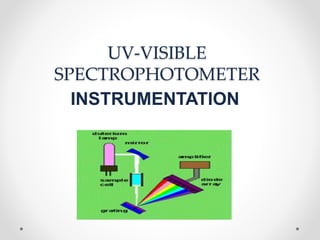
- 2. Components of UV-Visible spectrophotometer • Source • Filters & Monochromator • Sample compartment • Detector • Recorder
- 5. LIGHT SOURCES Various UV radiation sources are as follows a. Deuterium lamp b. Hydrogen lamp c. Tungsten lamp d. Xenon discharge lamp e. Mercury arc lamp Various Visible radiation sources are as follow a. Tungsten lamp b. Mercury vapour lamp c. Carbonone lamp
- 7. For Visible region Tungsten filament lamp • Use for region 350nm to 2000nm. • These measure most effectively in the visible region from 320 - 1100 nm • Instruments that only use Tungsten halogen lamps as the light source will only measure in the visible region.
- 8. For ultra violet region Hydrogen discharge lamp • Consist of two electrode contain in Hydrogen filled silica envelop. • Gives continuous spectrum in region 185-380nm. above 380nm emission is not continuous
- 9. Deuterium lamps: • Deuterium arc lamps measure in the UV region 190 - 370 nm • As Deuterium lamps operate at high temperatures, normal glass housings cannot be used for the casing. Instead, a fused quartz, UV glass, or magnesium fluoride envelope is used. • When run continuously typical lamp life for a Deuterium lamp is approximately 1000 hours, however this can be extended by up to a factor of three using PTR technology. • Deuterium lamps are always used with a Tungsten halogen lamp to allow measurements to be performed in both the UV and visible regions.
- 10. TUNGSTEN LAMP DUETERIUM LAMP
- 11. Filters &Monochromator The Monochromator/Filter will select a narrow portion of the spectrum (the band pass) of a given source • FILTERS ARE OF TWO TYPES: Absorption Filters Interference Filters MONOCHROMATORS ARE OF TWO TYPES: Refractive type PRISM TYPE Reflective type Diffraction type GRATING TYPE Transmission Type
- 12. FILTERS ABSORPTION FILTERS Absorption filters, commonly manufactured from dyed glass or pigmented gelatin resins Band widths are extremely large {30 – 250 nm} Combining two absorbance filters of diffeternt λmax
- 13. • The most common type of gelatin filter is constructed by sandwiching a thin layer of dyed gelatin of the desired colour between two thin glass plates.
- 14. FILTERS
- 15. INTERFERENCE FILTERS: • These are used to select wavelengths more accurately by providing a narrow band pass typically of around 10nm • These filters rely on optical interference (destructive wave addition) to provide narrow bands of radiation.
- 17. • Interference filter consists of a dielectric spacer film made up of CaF2, MgF2 between two parallel reflecting films. • As light passes from one medium to the other the direction and wavelength of light can be changed based on the index of refraction of both mediums involved and the angle of the incident and exiting light (For more look at Snell’s law). • Due to this behaviour, constructive and destructive interference can be controlled by varying the thickness (d) of a transparent dielectric material between two semi-reflective sheets and the angle the light is shined upon the surface. • As light hits the first semi-reflective sheet, a portion is reflected, while the rest travels through the dielectric to be bent and reflected by the second semi-reflective sheet. • If the conditions are correct, the reflected light and the initial incident light will be in phase and constructive interference occurs for only a particular wavelength
- 19. Refractive type prism Monochromator: • It consists of entrance slit, collimator lens, Prism, Focusing lens, Exit slit.
- 20. Reflective type prism Monochromator or Littrow type mounting :
- 21. GRATING MONOCHROMATOR • Gratings are rulings made on glass, Quartz or alkyl halides • Depending upon the instrument no. of rulings per mm defers • If it is UV-Visible no. of gratings per mm are more than 3600.
- 24. • The mechanism is that diffraction produces reinforcement. • The rays which are incident on the grating gets reinforced with the reflected rays and hence resulting radiation has wavelength governed by equation m λ =b(sin I + sin r) m – order λ – desired wavelength b – grating spacing i – angle of incidence r - angle of diffraction
- 25. TRANSMISSION TYPE GRATING: • It is similar to diffraction grating, but refraction produces instead of reflection • Refraction produces reinforcement • The wavelength of radiation produced by transmission grating can be expressed by d sin Φ λ = d = 1/lines per cm m
- 26. SAMPLE COMPARTMENT • Spectroscopy requires all materials in the beam path other than the analyte should be as transparent to the radiation as possible. • The geometries of all components in the system should be such as to maximize the signal and minimize the scattered light. • The material from which a sample cuvette is fabricated controls the optical window that can be used. • Some typical materials are: • Optical Glass - 335 - 2500 nm • Special Optical Glass – 320 - 2500 nm • Quartz (Infrared) – 220 - 3800 nm • Quartz (Far-UV) – 170 - 2700 nm •
- 27. DETECTORS • After the light has passed through the sample, we want to be able to detect and measure the resulting light. • These types of detectors come in the form of transducers that are able to take energy from light and convert it into an electrical signal that can be recorded, and if necessary, amplified. • Three common types of detectors are used Barrier layer cells Photo emissive cell detector Photomultiplier
- 28. BARRIER LAYER CELL or PHOTO VOLTAI CELL • It cosistitutes The steel support plate 'A' layer of metallic selenium 'B', which is a few hundredths of a millimetre in thickness. 'C' is a thin transparent electrically-conductive layer, applied by cathodic sputtering.
- 30. • It consists of a metallic base plate like iron or aluminium which acts as one electrode. • On its surface, a thin layer of a semiconductor metal like selenium is deposited. • Then the surface of selenium is covered by a very thin layer of silver or gold which acts as a second collector tube. • When the radiation is incident upon the surface of selenium, electrons are generated at the selenium- silver surface and the electrons are collected by the silver. • This accumulation at the silver surface creates an electric voltage difference between the silver surface and the basis of the cell.
- 31. Photo emissive cells Detector • Phototubes are also known as photo emissive cells. • A phototube consists of an evacuated glass bulb. • There is light sensitive cathode inside it. • The inner surface of cathode is coated with light sensitive layer such as potassium oxide and silver oxide. • When radiation is incident upon a cathode, photoelectrons are emitted. • These are collected by an anode. • Then these are returned via external circuit. And by this process current is amplified and recorded.
- 33. The photomultiplier tube • The photomultiplier tube is a commonly used detector in UV spectroscopy. • It consists of a photo emissive cathode (a cathode which emits electrons when struck by photons of radiation), several dynodes (which emit several electrons for each electron striking them) and an anode. • A photon of radiation entering the tube strikes the cathode, causing the emission of several electrons. • These electrons are accelerated towards the first dynode (which is 90V more positive than the cathode). • The electrons strike the first dynode, causing the emission of several electrons for each incident electron.
- 34. • These electrons are then accelerated towards the second dynode, to produce more electrons which are accelerated towards dynode three and so on. • Eventually, the electrons are collected at the anode. • By this time, each original photon has produced 106 - 107 electrons. • The resulting current is amplified and measured. • Photomultipliers are very sensitive to UV and visible radiation. • They have fast response times. • Intense light damages photomultipliers; • they are limited to measuring low power radiation.