2. BSNL
ALTTC TX-I 2
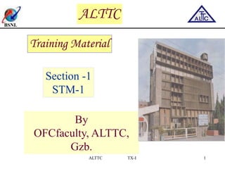
Base card . LTC6
1 Power supply unit
1 tributary card
Fan tray unit
Slot 1
Slot 2
Slot 3
Slot 6
Slot 5
Slot 4
Dummy
Dummy
Dummy
PSU
Base Card
Tributary Card
Fan
Tray
Unit
STM-1 sub rack view
3. BSNL
ALTTC TX-I 3
Power Supply unit
Power connection to PSU is via a 3-pin power D-connector
on the front of the unit.
The PSU is a single output isolated DC-DC converter. The
Converter provides 12V DC output.
The output circuits have blocking diodes for protection
When two PSUs are connected in parallel via the backplane.
Functional Description
4. BSNL
ALTTC TX-I 4
Power Supply unit contd.
Alarms and Protection
The PSU is protected against output short circuit, over
voltage and under voltage.
Input over voltage and under voltage protection is also
provided.
Output over voltage protection is latched and the unit will
not restart until power to the unit is removed and connected.
5. BSNL
ALTTC TX-I 5
Power Supply unit contd.
Power supply: 1 unit
• DC: -48V DC nominal, -40V to -60V DC
• Input Under/Over Voltage Protection:Shutdown: -
36V +/-4V/-65V +/-4V
• Input voltage high/low alarm setting user
configurable (default: -43.2V -56V)
• Output voltage high/low alarm fixed setting (not
user configurable)
Power consumption in fully loaded condition 120W
Fuse 6A slow, 20mm glass fuse
Backplane voltage 12V
Reverse polarity protection upto 75V
Detailed Specifications
6. BSNL
ALTTC TX-I 6
Line tributary card (Base Card)
The Base card (LTC6) is the heart of the sub rack
is pluged into Slot3.
LTC6 card supports two STM1 optical and two STM1
electrical ports.
LTC6 also has a provision to support tributary card.
8. BSNL
ALTTC TX-I 8
Base card . (cont..)
STM-1 optical interfaces
It has two SC-PC STM-1 optical interfaces on the front
panel.
The STM-1 transceivers are shipped with S1.1, L1.1 or L1.2
specification.
The type of the transceiver installed with the this card will be
indicated on the front panel.
STM-1e electrical interfaces
This card is designed to provide STM-1e interface. The STM-1e
interface is provided through BNC connectors.
9. BSNL
ALTTC TX-I 9
Base card .cont..)
Microprocessor
The Processor Sub System performs the configuration, control
& processing of all the other subsystems on the card
The software residing in this block controls the overall
management of the system.
A 1024 second timer is implemented on the card to check
for software errors.
If this timer expires, the operating system (OS) and application
software restarted.
This restart is service non-affecting, except for loss of
Management connectivity during the restart time.
10. BSNL
ALTTC TX-I 10
Protection
1+1 MSP (as per ITU-T G.841).
1+1 SNCP
SNCP: switching takes place in case of signal degrade
alarm also
VC-12, VC-3, VC-4 level path protection (SNCP)
11. BSNL
ALTTC TX-I 11
Aggregate Interfaces
2 x STM1 aggregate optical interface in the base card
2 x STM1 aggregate electrical interface in the base card
Note:- Either 2 optical interfaces or 2 electrical interfaces
can be used in the base card
12. BSNL
ALTTC TX-I 12
Fixed Slots
Slot 2 for Power Supply Unit
Slot 3 for Base card )
Slot 4 for tributary card (with 63- E1) . latching levers
13. BSNL
ALTTC TX-I 13
Tributary Interfaces
Tributary Card is a 63 E1/DS1 tributary interface card,
houses in the tributary line card.
This provides line interfaces to 63 E1 channels respectively
in both, add and drop directions.
This maps and demaps the E1 channels into SDH frame for
the tributary card to make the cross connects.
The software control is with the processor card through a
generic processor bus.
Power consumption is 14.6W at 12V.
14. BSNL
ALTTC TX-I 14
Total 63 for E1/DS1 add/drop
6 (3 sets), 48-pin metal connectors
Supports unframed E1/DS1 traffic
All ports can be user configured to take either E1
or DS1 traffic
Traffic connection through 120 ohm termination DDF
Power dissipation: 14.6 watts
Interface Cards
Tributary Card for E-1/ DS-1,Tributary,
16. BSNL
ALTTC TX-I 16
Sub rack front view
• The chassis will have 18 slots: 15 vertical and 3
horizontal
• For vertical slots, leftmost slot is slot number 1 and
rightmost slot is slot number 15.The PSU slot numbers
are 16 and 17 from left to right. MFC slot number is 18
• 3 horizontal slots will be used to house MFC and
redundant power supply cards
• 15 vertical slots will be allotted as: 2 slots for Cross
connect cards, 2 slots for system control card and 11
slots for tributary cards
17. BSNL
ALTTC TX-I 17
Sub rack front view- Line diagram
System
Control
Unit
#2
Tributary
Card
#2
Tributary
Card
#3
Tributary
Card
#4
Tributary
Card
#5
Cross
connect
Card
#1
Cross
connect
Card
#2
Tributary
Card
#6
Tributary
Card
#7
Tributary
Card
#8
Tributary
Card
#9
Tributary
Card
#10
Tributary
Card
#11
System
Control
Unit
#1
6T
Tributary
Card
#1
Cable tray
PSUL #1 PSUL #2
MFC
18. BSNL
ALTTC TX-I 18
STM1 card with 2 No. of
Optical Interface
STM1 Card contains one or two STM-1interfaces,
which can either be configured as tributary interface
• Automatic Laser shut down is provided for safety
requirements
• Status LED glows GREEN when the power is on and
the card is recognized
• Active LED glows GREEN when the card is fully up
ie., all devices are initialized and ready to carry traffic
19. BSNL
ALTTC TX-I 19
Tributary Card E1/DS1
• Traffic
• Each TET21/TET28 card can add or drop
21E1/28E1/DS1’s via 2, 62-pin connectors
• Status LED glows GREEN when the power is on and the
card is recognized
• Active LED glows GREEN when the card is fully up ie.,
all devices are initialized and ready to carry
• An interface is provided for E1 monitoring purposes
20. BSNL
ALTTC TX-I 20
Tributary Card E3/DS3
Interface
• Each card has 2 BNC connectors, one for E3/DS3
transmit and other for E3/DS3 receive
• The LED indicators on the faceplate give the card
Active and the Status indication to the user
• Status LED glows GREEN when the power is on and
the card is recognized
• Active LED glows GREEN when the card is fully up
ie., all devices are initialized and ready to carry traffic
21. BSNL
ALTTC TX-I 21
STM4 Aggregate card
Optical Interface
• This card has 1 STM-4 interface
• This card can either be configured as aggregate or
tributary interface
• Automatic Laser shut down is provided for safety
requirements
• Status LED glows GREEN when the power is on and the
card is recognized
• Active LED glows GREEN when the card is fully up ie.,
all devices are initialized and ready to carry traffic
22. BSNL
ALTTC TX-I 22
Ethernet card
• The front view shows the line interfaces to 8,
10/100Mbps ports
• Status LED and Active LED
• Status LED glows GREEN when the power is on and
the card is recognized
• Active LED glows GREEN when the card is fully up
ie., all devices are initialized and ready to carry traffic
23. BSNL
ALTTC TX-I 23
Cross Connect Card
• Two cross connect cards are available for redundancy .
• The STM-4 cross connect card performs timeslot
interchange and grooming function in sub rack .
• Different front panel interfaces supported are:
– A push button switch for “hot swap” of redundant SCU
– LED indicators for ‘active’ and ‘status’
• Status LED glows GREEN when the power is on and the
card is recognized
• Active LED glows GREEN when the card is fully up ie., all
devices are initialized and ready to carry traffic
24. BSNL
ALTTC TX-I 24
• The two SCUs can be operated in parallel. If any one SCU
fails, it is automatically isolated from the circuit.
• The System Control Unit card performs the configuration and
control of the different subsystems in the sub rack.
• The SCU card contains the processor, memory and hard
disk required to operate the sub rack.
• Different front panel interfaces supported are:
– A node diagnostic port on RJ45
– A push button switch for “soft reset”
– A push button switch for “hot swap” of redundant SCU
– LED indicators for ‘active’ and ‘status’
System Control Unit
25. BSNL
ALTTC TX-I 25
• The two PSUs can be operated in parallel. If
• any one PSU fails, it is automatically isolated from the
circuit.
• Due to the high power requirements of cards
• the Back plane voltage is selected to be 12V
• while the input to the Power Supply Unit is - 48V
• The “power” LED turns green when the input voltage is
in range and indicates red on any input abnormality
• The “Active” LED turns green when the outputs of the
supply are working and within range
Power Supply Unit
26. BSNL
ALTTC TX-I 26
Multi Function Card
• It is used to implement miscellaneous interfaces.
• Engineering Order Wire (EOW)
• NMS Interface
• Alarm input/output
• Serial Ports
27. BSNL
ALTTC TX-I 27
Protection
· SNCP, 1+1 MSP (as per ITU-T Rec.G.841)
· VC-12, VC-3 level path protection
· Optional hardware redundancy:
Power Supply, System Control Unit, Cross connect and
Aggregate Card level.
· 1:3 E1 tributary protection
Protection
28. BSNL
ALTTC TX-I 28
Provisioning
• The circuit provisioning feature is used for provisioning interfaces and
creating circuits between two NEs .
• The features that can be provisioned include:
• MSP/ASP Groups
• Cross Connects
• Order wire
• Environmental Alarms
• STM Ports
• AUG
• AU
• TU
• E1/DS1/E3/DS3 ports
• Ethernet ports
• VC Group
29. BSNL
ALTTC TX-I 29
Provisioning - VC Group
• To provision VC Group
• Click VCG Group in the provisioning page. All the VC
Groups in the node are displayed in the Provisioning VCG
Interface page(VCG-1-3-101)
• Click the desired VCG . Select the desired values against
the corresponding fields
• Click Submit . Success message is displayed upon
confirmation
30. BSNL
ALTTC TX-I 30
Addition VC to VCG
• To add VC to VC group
• Click the desired VCG from the provisioning VCG interface
page
• Click Add new VC to this VC Group. The VCG Association
page is displayed
• Enter the corresponding values against the fields
• Click Submit. Success message is displayed upon confirmation
• To delete VC from VC Group
• To delete a VC from VC group. Select VC that has to be
deleted by checking it in the delete column in the VCG interface
page.
• Click Submit. Success message is displayed upon
confirmation
33. BSNL
ALTTC TX-I 33
ALTTC TX-I 33
Technical Specification - Cross
Connect card
Upto 48x48 STM1 or equivalent (grooming at
the
level of VC12/VC-11)
Fully non blocking
Line to Line, Line to Tributary, Tributary to
Line,
Tributary to Tributary
Power dissipation : 30 watts
34. BSNL
ALTTC TX-I 34
ALTTC TX-I 34
Power Supply Module
Power supply: 2 units (2 connectors for redundancy)
•DC: -48V DC nominal, -42V to -56V DC
•Input Under/Over Voltage Protection:Shutdown: -35V
+/- 4V/-65V +/-4V
•Input voltage high/low alarm setting user
configurable (default: -43.2V -56V)
•Output voltage high/low alarm fixed setting (not user
configurable)
Power output 270W
Fuse 10A Slow Blow fuse
Backplane voltage 12V
Reverse polarity protection is continuous
35. BSNL
ALTTC TX-I 35
ALTTC TX-I 35
Multifunction Interface Card .
Alarm Display panel
Power dissipation: 8 watts
OAMP module
•Diag interface: Remote login (tejas personnel only) -
RJ45 connector
•
Alarm IN interface: external alarm in . DB9 pin
connector-7 Alarm IN
•
Alarm OUT interface: external alarm out . DB9 pin
connector- 4 Alarm out (Hooter can be out alarm)
•
Alarm Reset button to reset the hooter
•NMS interface: CSMA/CD based LAN transceiver of an
Ethernet link . RJ45 connector
36. BSNL
ALTTC TX-I 36
ALTTC TX-I 36
Protection
1+1 MSP (as per ITU-T G.841).
1+1 SNCP
SNCP: switching takes place in case of signal degrade
alarm also
VC-12, VC-3, VC-4 level path protection (SNCP)
MS-SP
37. BSNL
ALTTC TX-I 37
ALTTC TX-I 37
Fixed Slots
Slot 1 and 15 for Power Supply Module
Slot 8 and 9 for cross connect card
Slot 16 is for MFC
Slot 17 for Fan tray unit
38. BSNL
ALTTC TX-I 38
ALTTC TX-I 38
Aggregate Interfaces
Aggregate card 018 (8 x STM1 O/E)
•8 x STM1 O/E
Aggregate card 2.5 Gbs. (1 x STM16)
Interface for aggregate ports
•SFP lasers for aggregate ports
•Online Tx & Rx power measurement (Non
service disruptive)
39. BSNL
ALTTC TX-I 39
ALTTC TX-I 39
Tributary Interface in 63 No. of E1/DS1)
Ethernet card (2 x 1000Mbps Ethernet optical
interface)
Tributary Interfaces
40. BSNL
ALTTC TX-I 40
ALTTC TX-I 40
Visual indicators for cards
Active LED
•Amber: On insertion/power ON
•Green: Initialization Complete/In use
•Red: Card Inactive/Admin Down
Status LED
•Amber: On insertion/power ON
•Green: Initialization Complete
•Red: Hardware error/Admin down
42. BSNL
ALTTC TX-I 42
ALTTC TX-I 42
Base card . LTC6 (cont..)
STM1
•S1.1 - Rx sensitivity:-28dBm Rx overload: -8dBm
Max Tx power: -8dBm
•L1.1 - Rx sensitivity:-34dBm Rx overload: -10dBm
Max Tx power: 0dBm
•L1.2 - Rx sensitivity:-34dBm Rx overload: -10dBm
Max Tx power: 0dBm
1+1 SNCP
SNCP: switching takes place in case of signal
degrade alarm also
VC-12, VC-3, VC-4 level path protection (SNCP)
Interface cards (contd..)
A018 (A . Aggregate, 0 . Optical, 1- STM1 capacity, 8 . no of ports)-Laser
Details
43. BSNL
ALTTC TX-I 43
ALTTC TX-I 43
Electrical Interface cards (cont..)
(Tributary,E-E1,T-T1,63-no of ports)
Total 63 for E1/DS1 add/drop
6 (3 sets), 48-pin metral connectors
Supports unframed E1/DS1 traffic
All ports can be user configured to take
either E1 or DS1 traffic
Traffic connection through 120 ohm
termination DDF
Power dissipation: 14.6 watts
44. BSNL
ALTTC TX-I 44
ALTTC TX-I 44
Ethernet Interface cards (cont..)
(T-Tributary card, R-Gig E Ethernet )
2 optical ethernet ports
•
SFP lasers for the optical interfaces
•Online Tx & Rx power measurement (Non service
disruptive)
Each port is configured to take 1000 Mbps, full
duplex mode
Backhaul bandwidth is max 2xSTM4, any
combination of the bandwidth from individual ports
Transport card supports :Auto negotiation, GFP-
F,VCAT and Link Integrity
47. BSNL
ALTTC TX-I 47
ALTTC TX-I 47
•T
o
Site preparation
The power supply requirements for system :
• AC- 230/110 V 50/60Hz +/. 10%
• DC Input- -39 to -60V DC from SMPS Power plant and
MFC batteries
• DC Earthing (Ring type 0.5 Ohm resistive max.)
Circuit breaker 2A (MCB may be provided separate
for each system
48. BSNL
ALTTC TX-I 48
ALTTC TX-I 48
Primary Requirements
Dust free environment : Adequate space and adequate air
circulation
no direct entry of the dust from the outer environment
Temperature requirement : Optimum 18 to 23 degree cellcious
(Maximum Temp. should not be 40 degree cellcious) Air fan should
be
always operated in the equipment itself for circulating the heat
generated.
Lay out should be as per the standards prescribed by the
BSNL/supplier
and should be approved by the competent authority
Antistatic flooring
Rack Installation –
ensure that the rack is not overly congested,
because each unit generates heat. An enclosed
rack should have lowered sides and a fan to
provide cooling air
49. BSNL
ALTTC TX-I 49
ALTTC TX-I 49
Preparation before installation
Flexibility to jack in any card in any of the tributary slot
Choose cards based on requirement
Handling/Installing/Scoring or replacing cards and pluggable
module requires
a. Wear wrist strict
b. Not to touch solder side of the any module, pin configuration
or any component
c. Inspect module and pin connectors for any damage
d. Store uninstalled cards in shielded box/plastic wrapper
e. Put the cap on all optical port unused/un fiber.
50. BSNL
ALTTC TX-I 50
ALTTC TX-I 50
Installation contd…
Alarm Cable 7 no of twisted their with 15 way D type connector in MFC
NMS cable it is cross/straight (if hub is used) with RJ45 connector to the
NMS port in the MFC
Craft / modem cable : 9 pin RS 232 type serial cable (female) to be
connected to the serial port 1 & 2 on MFC
48 volt earthing cable : it is the single strand cooper cable used for +ve
supply pin grounding
All the cables / Optical fibre used for connectivity should be laid as per the
Site engineering practice/guide lines and along the right side of the rack.
51. BSNL
ALTTC TX-I 51
ALTTC TX-I 51
Installation of the chassis to the rack
Node View
The positions of cards in the rack
Slot no. 6,7,8&9 all fix slots and
The slot no. 1 to 5 and 10 to 15
are transaction slot
Slot No. Card
0 Back Plane
1&13 STM aggregate card
2,3,4 E1 Tribute
(Trib ext16,21,28) with
62 D type connector
5 TE31/TE33 for VC3
with BNC connector
6&7 XCC control card
(D9 connector for BITS)
52. BSNL
ALTTC TX-I 52
ALTTC TX-I 52
Installation of the chassis to the rack
Slot No. Card
8&9 SCU card
system control unit
with RJ45 diagnostic
connector
16 Power supply 1&2
(with three pin
connector)
17 Fan tray
18 MFC (Multi frame card)