
Recommended
More Related Content
What's hot
What's hot (20)
Similar to Saga of a steel bridge
Similar to Saga of a steel bridge (20)
Recently uploaded
Recently uploaded (20)
Saga of a steel bridge
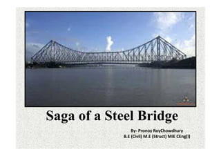
- 1. Saga of a Steel Bridge By- Pronoy RoyChowdhury B.E (Civil) M.E (Struct) MIE CEng(I)
- 2. • The question of bridging the river Hooghly flowing past the twin cities of Howrah and Calcutta was considered for a long time past as early as 1860. • This is because Calcutta was then a very important settlement of the British in India by the bank of the river Hooghly. • The Calcutta port was a very bustling port, and the Howrah station a terminal station of the then East Indian Railways where railways used to bring passengers and goods from all over India.
- 3. In 1871 an Act was passed to enable the Lieutenant Governor (Sir G. Campbell) to construct, at the expense of Government, a bridge across the Hughly, to fix tolls, and to appoint the Port Commissioners to carry out the purposes of the Act. In moving for leave to bring in this Bill, the Hon’ ble Sir Ashley Eden stated that a contract had been entered into with Sir Bradford Leslie and that it was hoped the bridge would be completed by the beginning of 1873, at a cost not exceeding 150,000 pounds. The several portions of the bridge were manufactured in England and put together in Bengal. The construction of the Calcutta- Howrah floating-bridge over the Hughly was completed in 1874 under the supervision of Mr. (Sir) Bradford Leslie, K. C .I. E.
- 5. Erstwhile Pontoon Bridge designed by by Sir Bradford Leslie
- 6. Sir Bradford Leslie K.C.I.E (1831-1926)
- 7. Crossing the river Hooghly was an unpleasant predicament across the narrow pontoon bridge constructed by Sir Bradford Leslie in 1874. The greater difficulty in deciding a proper technology for the proposed Howrah Bridge was due to the fact that the Calcutta port was entirely dependent on the navigable channel of river Hooghly and construction of any permanent pier like structure in the valley of the river may actually effect navigation due to the vagaries of silting and scouring in the stream channel and consequent reduction of navigable depth.
- 8. • In the year 1874 Sir Bradford Leslie the then Chief Engineer of East India Railway designed and built a pontoon bridge which connected Howrah with the city of Calcutta, then the capital of British India. • Engineers thought it shall not be a pragmatic decision considering the fact that river Hooghly is a tidal river, and the structure shall be exposed to severe cyclonic storms & tidal bores which frequents in the river Hooghly. • However the structure effectively survived, without any major accident. Although the bridge was built to last for 25 years but it quiet effectively served almost 3 times the predicted life of the structure. However with passage of time the bridge became inadequate.
- 9. •A technical committee of 1909 floated global tenders for design and specifications. •Some 23 firms submitted technical proposals for the same in 1913. •The expert committee reported exhaustibly on the submitted proposals. •The prize was awarded to a German design submitted by the MaschinanFabrik Augsberg et Nurenburg Co.
- 10. • The German proposal basically consist of a floating longitudinal pontoon bridge with a 200ft (about 60.96m ) opening span of “scherzer rolling type” bascule principle with counter weighted bascule of 100ft (30.48m) each rising up to a perpendicular position to effect the opening. Salient features of the German proposal are given elsewhere . • The project was not awarded to the German Company at the time of prevailing war, so the expert committee finally came to the conclusion that the design did not meet all the requirements and decided to reject all the design submitted, a new set of specification was put up and it was decided that more designs and tenders shall be called. • The new specification also suggested in favour of a floating bridge with opening spans rather than a fixed bridge owing to much better average gradient obtained on a floating bridge. • Inspite of significant effort the construction of the bridge was not fruitful due to outbreak of the First World War (1914-1919).
- 11. Proposal for layout of Howrah Bridge as submitted by German Company Maschinenfabrick Ausberg Nurenberg (Figure adopted from the article "Howrah Bridge Problem" - By F.R. Bagley, the IEI journal Vol.-I, September, 1921, Pg.-53-71)
- 12. •The other significant proposal was received from Sir Bradford Leslie and he submitted a proposal for a pair of floating bridge at the present site, which he referred to as “twin bridge”- a very much improved type from the existing pontoon bridge with a very ingenious type “draw spans” which was entirely a new type of innovation designed to withdraw and restore the opening span within two or three minutes instead of half an hour as compared to the then old pontoon bridge, see fig for layout of the bridge. •It was claimed that the new proposal ensured much more stability with increased length of pontoon and punt shape ends. The four mooring posts’ on each side of the opening span will keep the deck span exactly in position and it was claimed that this arrangement shall be a major improvement on stability.
- 13. Twin Bridge Proposal as submitted by Sir Bradford Leslie (Figure adopted from the article "Howrah Bridge Problem" - By F.R. Bagley, the IEI journal Vol.-I, September, 1921, Pg.-53-71)
- 14. The Single span Arch bridge proposal of Howrah Bridge by Sir Basil Mott (Figure adopted from the article "Howrah Bridge Problem" – By F.R. Bagley, the IEI journal Vol.-I, September, 1921, Pg.-53-71)
- 15. Sir Basil Mott a distinguished Bridge Engineer was requested by the then Bengal Government to advise of the type of Bridge across Hooghly. Sir Mott visited the site in the winter of 1916 and reported around 1918 that the best type of bridge in his opinion shall be a single span arch Bridge.
- 16. •Sir Basil Mott a distinguished Bridge Engineer strongly recommended the construction of a single span arch type bridge which he considered to have distinct advantages over any floating bridge or bridge with piers as presenting least possible obstruction to river traffic and with considerably less risk of scour and also simplifying the mechanical difficulties of opening span. •He recommended a single span steel arch of about (1400ft) ( 426.72m ) span with a roadway suspended from it at a height giving 25ft of headway at highest water level, and an opening span of 200ft (60.9m) clear width of the scherzer or turnnion pattern. •Although it was also admitted that there is considerable difficulty in ensuing safe foundations for the enormous thrust coming on abutments in Calcutta alluvium. But Sir Mott claimed to overcome such difficulties are related to foundation. He also claimed that the Arch type structure also has aesthetic appearance.
- 17. •Historically several committees were formed to discuss the nature of the new Howrah Bridge which shall replace the existing pontoon bridge. Significant among these expert technical committees was the widely referred ‘Mukherjee Committee’. •The committee was chaired by the well known Bengali industrialist Sir Rajendranath Mookherjee, the other members included, Sir Clement Hindley, the then Chairman of Calcutta Port Commissioners and Mr. J. Mc Glashan Chief Engineer of Kolkata Port Commissioners in 1921. This committee suggested for Cantilever Bridge construction.
- 21. Sir Clement Hindley, the then Chairman of Calcutta Port Commissioners
- 22. In the year 1926 the new Howrah Bridge Act was passed. In the year 1929 the consultant firm Messers Rendel, Palmer and Tritton of Westminster presented a report on a bridge across river Hooghly between Howrah and Kolkata to the Calcutta Port Commissioners. The report (as learnt from “the Engineer” 7 Feb, 1930) is divided into two sections each dealing with an alternative design, the first being concerned with a bridge of cantilever type, while the other discussing a floating non opening bridge and in case a preliminary cost of estimate.
- 24. Side elevation and cross-section of Balanced cantilever steel truss bridge Howrah Bridge put up by Messers Rendel Palmer Tritton (figure adopted from "The Engineer" Journal, February 7th, PP 152, 1930)
- 25. Global tenders were floated in 1934-35 on the basis of decision of a majority of the sub-committee of Calcutta Port Commission ("The Engineer" 17July, 1936) recommendations were made to accept the tender of the Cleveland Bridge and Engineering Company Ltd. of Darlington, for construction of New Howrah Bridge over river Hooghly in accordance with the official design prepared by Messers. Rendel Palmer & Tritton of Westminster. The contract was awarded to Cleveland Bridge and Engineering Company Ltd, with recommendation to use Indian Steel if proper quality of steel may be identified. The cantilever bridge was to span 1500ft (457.2m) across Hooghly and the width of roadway 71ft (21.6m).
- 26. A simply supported beam loaded with an u.d.l exhibits a maximum B.M. of wl2/8 at the mid span, however for a fixed beam loaded with u.d.l. It is seen that the maximum B.M. at mid span reduces to wl2/24 thus bending stress is much reduced, however at supports there is a hogging B.M. •But there are some well known practical disadvantages for fixed beam they may be indicated only for ready reference:- •It is practically difficult to maintain the two ends of fixed beam at same level during execution, any subsidence of support relative to the other support shall induce sinking moments at the support tops. •Temperature variation will also produce large stress. •When the beam is subjected to variation of live loads such as wheels passing over a bridge degree of fixity at the end supports gets reduced due to vibration of beams.
- 27. The above objections may however be much obviated by adopting the double cantilever construction. In this method at the points of contra-flexure of the fixed beam, hinged joints are introduced. Now the beam consists of a central simply supported girder, supported on the ends of cantilevers. The bending moment diagram and the elastic curve for this compound beam will remain the same as for fixed beam. After introduction of the hinged joints, temperature changes and support sinking will not affect the bending moments. In comparison to totally simply support span, in cantilever structures positive B.M. are much reduced due to reduction of length of central span by supporting cantilever end span. In practice obtaining perfect fixity for end cantilever supports may be difficult to achieve. So the end cantilever spans are often flanked to develop what is called anchor spans. With such an adjustment, difficulty in achieving perfect support fixity may be considerably waived.
- 28. Bending moment diagram, o1& O2 are distance of points of contraflexures from support. Fixed Beam
- 29. Double Cantilever with hinge at B & C The maximum B.M. in beam BC (simply supported span equal to For cantilever span portion AB maximum B.M. is given by Compound Beam
- 30. Thus the Maximum B.M. in the simply supported span is whereas for the cantilevered structure the maximum B.M. is which is about 55% of the simply supported span, hence about 45% reduction in bending stress is achieved in balanced cantilevered structure; so steel consumption is economized in the truss, M=f x Z where M = B.M, f= bending stress and Z=section modulus. Thus when M is on lower side Z required is less so section is economical. Comparison between Simply supported and cantilevered structures
- 31. Balanced cantilever with flanking spans AE and DF and B and C are internal Hinges Balanced Cantilever Beam with Anchor Span (flanking span)
- 32. Basic Layout of Balanced cantilever truss Bridge
- 33. Hinge connection through eye-bar between cantilever arm and the suspended span of suspended balanced cantilever bridge truss
- 34. •A cantilever bridge consists of a simple span being carried by two overhang or cantilever portion and the suspended span between the cantilever spans are connected with hinge connection. •The main advantage of a cantilever bridge over a continuous bridge is that it is statically determinate and hence easier to analyze and also not subjected to changes in stress due to support movements. •Cantilever bridge construction are generally adopted for deep gorges to be crossed by a single spans without any intermediate pier, and the impracticability of using false work because of the danger of washout due to high flood in river valley. •Although cantilever bridge is less rigid and deflects more vertically than a single span bridge, but cantilever bridge is far more rigid than suspension bridge. But it is to mention that, each of the technology for bridge engineering has their own relevance in engineering construction.
- 35. •The most significant structural feature in a cantilever bridge truss is the provision for connection between a suspended span to the cantilever arm. •There are hinge connection between cantilever arm and the suspended span, this hinge is connected between two arms by a vertical link ; The link carries only vertical forces. •Pin connections are provided for the vertical link connecting the cantilever & suspended span. Such pin connections are provided to achieve zero moment or free rotation at the connections. In order to minimize friction at the said joints high grade machining is done to make the pin and pin hole surface smooth. To make the link between cantilever and suspended span, eye bars are generally used. •The ends of the eye bars are forked and eye hole is drilled in this portion. The eye bar is inserted in the jaws of the fork end and the pin is placed, pin is cylindrical shaped. The pin in the joint is secured by means of a cotter pin or screw. Structurally the pin is designed as a cylindrically shaped beam.
- 36. •A common way to construct a cantilever bridge truss is to counter balance each cantilever arm with another cantilever projecting in the opposite direction, forming a balanced cantilever bridge truss. When the courter balancing arm is attached to a solid foundation it is called an anchor arm. Thus in a bridge truss built on two pier foundation, there are four cantilever arms. • Two of them span the obstacle (river valley) and the two are the anchor arms which extend away from the obstacle. The Howrah Bridge is an excellent example of suspended balanced cantilever steel truss bridge. The deck is carried on the lower chord of the truss hanging from suspenders.
- 37. •The Howrah Bridge is a suspended balanced cantilever steel truss bridge. The bridge is primarily constructed of built up steel sections riveted together. • The bridge is of through type; the deck hangs between the two main piers from suspenders (hangers 39 nos) from the lower chord. • The anchor portion does not carry the deck and they are located at ground level. The main span of the bridge is 1500ft (457.2m) between center of the main pier. • The main span is composed of two cantilever span and a suspended span. The two cantilever arms are 468ft (142.6m) long and a suspended span is 564ft (171.9m). • The anchor arms are each 325 feet (99.06m) long. The main trusses of the bridge are spaced 76 feet (23.16m) centers and the road is 71 feet wide (21.64m) between the kerbs accommodating eight lanes of vehicular traffic and 2 nos, 15 feet (4.5m) cantilever footways on either side of the bridge for the pedestrian. • The two towers of the bridge are 270 feet (82.3m) high above road level and 76ft (23.16m) apart at the top the giant towers were bolted down at the base with the pier. The cantilever and the suspended span are connected with pin connection, forming a hinge. This arrangement is made through vertical member which carriers only vertical axial load. • There are expansion joints between the cantilever and the suspended span to accommodate charges of temperature due to heating & cooling of the steel truss, by sun rays etc. the main towers are sufficiently flexible to accommodate elastic deformation of the structure in the plane of the bridge.
- 38. Soil reports of the main pier of Howrah Bridge indicated that there was existence of a bed of hard clay 97ft (29.56m) below the surface of Calcutta and 79ft (24m) below the surface of Howrah side pier respectively. Such revelation of clay bed greatly simplified the scope of construction of foundation for main pier of a single span bridge which was out of question until then and without such layer of soil it would have been and almost insuperable task; for enormous loads shall be coming on the abutment of the proposed bridge. Soil report
- 39. • In 1921, The Chief Engineer of Post commissioners conducted test to ascertain bearing capacity of the soil, and found that the bearing capacity of the clay bed was satisfactory for a heavy bridge structure and settlement was almost negligible. • Messers Rendel, Palmer & Tritton the consultant Engineers firm also conducted test with cylinders 6ft (1.82m) in dia sunk 10 ft. (3m) in hard clay at king Georges dock of Calcutta Post Commissioners (Netaji Subhas Dock) The test report of Rendel, Palmer & Tritton indicated that on both sides of the river the clay bed shall provide for a factor of safety of exactly 2, under the worst conditions of load and wind pressure. • It was Justified that such load combination can never come in actual practice, as at such a high wind velocity there can be little ( if any) live load crossing the bridge.
- 40. •The foundation for the two main piers were giant monoliths each of 181’6” (55.18m) long and 81’6” (24.71m) wide and each contain 21 nos. dredging shafts each 20’6” (6.12m) square. •This Arrangement provided sufficient no. of dredging shafts to give effective control along the major and minor axis while providing ample weight on the monolith shell during sinking to overcome skin friction and resistance of the cutting edge. •Monoliths are essentially open cassions of reinforced concrete or mass concrete construction with heavy walls. • Open cassions and monoliths are suitable for foundations in rivers and water ways where soil predominantly consists of soft clays, silt & sands, since these materials can be readily excavated by grabbing from open wells and they do not offer high resistance due to skin friction to the sinking of cassion.
- 41. Monolith Cassion foundation of Howrah bridge under construction
- 42. foundation cap of Howrah bridge under construction
- 43. Calcutta side pier of Howrah bridge showing one of the main tower of the bridge truss
- 44. • As per recommendation of the tender for Howrah bridge, it was required to use steel of appropriate quality & engineering property preferably manufactured in India. In connection to the same a special type of steel called High tensile low alloy steel containing Copper & Chromium known commercially as “Tiscrom” was manufactured at TISCO Jamshedpur. • The Chemical composition of high strength steel is so balanced as to obtain the requirement of integration of several properties such as strength, resistance to impact, increase of corrosion and abrasion resistance, ease of forming satisfactory welding. The available quality of steel especially carbon steel which was widely used for bridge truss construction could not take high stress before failure so large sections were required adding to unnecessary dead weight and material cost. Materials of Construction
- 45. •The quantity Howrah Bridge steel weighed about 26500 tones consisted of High tensile steel, mild steel, cast and forged steel. •About 17500 tons of High tensile steel was used for Bridge construction.
- 46. Carbon (C )- 0.23% to 0.28% Manganese (Mn)- 1.0% to 1.3% Chromium (Cr)- 0.5% to 0.6% Copper (Cu)- 0.3% to 0.6% Silicon (Si)- not more than 0.2% Sulphar (S) & Phosphorus (P) not more than 0.05% each The chemical composition of the steel was as follows :-
- 47. Nature of stress Stress in t/sq in Axial tension (basic) = 12.65 (174.4 N/mm2) Axial tension (Maximum) = 17.00 (234.4 N/mm2) Axial Compression in Pin – ended strut of length l and radius of gyration r = 13.8 (1 – 0.0057 l/r) Maximum 10.75 (148.2 N/mm2) Bending : Tension flange = 12.65 (174.4 N/mm2) Un-Stiffened compression flange of length l and width b = 12.65 (1-0.0112 l/b) Shear in web (avg) = 7.5 (103.4 N/mm2) Shear in shop rivets = 9.0 (124.1 N/mm2) Bearing in shop rivets = 18.0 (248.2 N/mm2) The engineering properties of steel are as follows
- 48. In 1914 the famous American bridge Engineer J. A. Waddell in a paper (Possibilities in bridge construction by the use of high-alloy steel, ASCE, pp 1-38, 1914) to American Society of civil Engineers wrote “As the future development will necessitate the building of many very long span bridges, it is almost a necessity that there be found an alloy steel of great strength and of moderate cost. Such alloy is not going to be discovered by accident, but only by a lengthy and exhaustive series of experiments laid out systematically in advance." Waddell visualized steel with yield stress upto 45 tones / sq inch (695 N/mm2). In Howrah Bridge structural steel with yield stress of 23 tones / sq inch (355 N/mm2) was successfully used.
- 49. A large consignment of such steel about 23500 Ton was supplied by TATA Iron & Steel Co. for construction of Howrah Bridge super structure. Such a lofty achievement revolutionized the steel industry in India. The issue was highly recognized and was even discussed at the Presidential address of Indian Science Congress, Benaras, 1941.
- 50. •But a major problem for using low alloy high tensile steel at the time of execution of Howrah Bridge was that British standard B.S.S. No. 548 (1934) did not specify any working stresses. Although B.S.S. 449 (1948) specified some working stress but it was intended for steel buildings and not for Steel truss bridges. • Thus Bridge Engineers therefore had to exercise their own individual judgment in deciding allowable stresses for high tensile steel used in bridge work.
- 51. • The fabrication & erection of steel work of the Howrah Bridge across river Hooghly of Calcutta was carried by the contractor agency Cleveland Bridge & Engineering Company Ltd. of Darlington, UK as per design of consultant firm Rendel Palmer & Tritton, Westminster London. • All the fabrication of steel work was however carried out by the sub-contractor Braithwaite Burn and Jessop Construction Company Ltd. in its four nos. of separate workshops in Calcutta. BBJ was a consortium of three Engineering companies Burn and Co. Braithwaite and Jessop. The company was formed in 1935. Fabrication of Structural Member
- 52. Fabrication of Well kerb for cassion foundation of Howrah Bridge
- 53. Fabrication of Links of the Anchorage truss
- 54. Fabrication of the lower section of the bridge tower
- 55. Girder of the anchorage truss under fabrication
- 57. • About 3700 tons of steel work was used for the main towers of Howrah Bridge. Each tower stands on 2 inch (50mm) thick mild steel slab to which the holding down bolt of the structural base of the tower is fired by tap bolting for accepting the holding down bolt. The steel slab sits on supporting monolith. • The structural base of the tower consists of seven plate Girders. The upper flanges of which are sat up on a rake square to slope of the tower. Between seven nos. base girders are no. of diaphragms corresponding with the webs of the adjacent sections. The bottom section of each tower is offset to provide a support for bearing of the main girder. The bearings were fabricated of steel and each weighed 27 tons. The complete base measured 23 ft. (7.0m) by 17 ft (5m). • Above the bottom section the tower is rectangular in cross-section having uniform width of 11 ft 6 in (3.5m) throughout in side elevation, and tapering in transverse dimension from 8 ft 6 inch (2.6m) at bottom to 4 ft 4 inch (1.32m) at top. The tops of towers are finished with cap plates on which saddles are fitted. The saddles weight 115 ton and fabricates with high tensile steel plates, 157 inch (3.9m) wide and 7/8 inch (21mm) thick. Each saddle carries four pins two of 30 inch (750mm) dia for the upper chord and two of 18 inch diameter for the main web member.
- 58. Anchor, cantilever girder & suspended span About 12000 ton steel work was used in anchorage and cantilever arms of the bridge. In the suspended span approximately 2100 ton of steel work was used. The ends of the suspended span called for a number of fitted bolts connections, both for temporary jacking steel work to adjust the relative positions of the two halves during erection, and to enable the top and bottom chord gaps to be adjusted separately.
- 59. Photo showing hinge and eye bar joint between Cantilever span and suspended span of Howrah bridge
- 60. Anchor span view of Howrah bridge
- 61. Photo showing steel grillage connection with the foundation of anchor span of Howrah bridge
- 62. • The road way has a clear width of 71 (21.6m) feet between the kerb and the total width of the deck is 108 feet 9 inch (35.15m) between the centers of fascia girders at the outer edges of two cantilevered footways. • Deck hangers are spaced 76ft (24.16m) a past c/c transversely. The deck system consists of cross girders at each pair of hangers, with longitudinal floor beans spanning between the cross girders, transversal floor joists spanning across the longitudinal floor beans and pressed steel toughing carrying the road concrete on top. The road way troughing is filled with concrete and a 3-inch thick (75mm) R.C. slab is placed on top. • The slab is topped with 2-inch thick (50mm) concrete wearing surface and is securely anchored to the troughing by hoops 8 inches (2.4m) apart centre to centre. The footways are carried on cantilever brackets built on ends of cross girder and the paving consists of 3-inch thick (75mm) concrete slab with 1 1/2 inch thick (37.1mm) I.P.S. flooring. • The bridge deck has ruling gradient of 1 in 40 from either end joined by a vertical curve of radius 4000ft (1200m), the cross gradient of deck is 1 in 48 between the kerbs. Deck system
- 63. Photo showing the roadway of Howrah bridge hanging from the bottom chord of the bridge truss through suspenders.
- 64. •The superstructure of the bridge was erected with the help of a special type of crane called creeper crane. •It was designed especially for the work by the agency called Wellman Smith Owen Engineering Corporation Ltd. The crane unit was specially designed for the purpose of erection of the cantilever bridge. •The crane consisted of two 60 ton slewing and derricking jib cranes lifting load at 40ft (12.19m) radius on a main frame structure designed to travel along the top chord, the cranes had to creep the anchor arm lying at an angle of approximately 30º to horizontal and pass over the apex of the tower and descend on the main cantilever chords of the central span at angles varying for about 22º at the tower to about 9º near the end of the arm. Therefore to form a path along which the crane has to move ‘fleeting tracks’ were provided and placed on bridge chords.
- 65. Creeper crane used for erection of superstructure of Howrah bridge truss
- 66. Howrah bridge truss erected by using creeper crane, showing stages of erection
- 67. The bridge was officially opened to service in 1943, in the midst of 2nd world war, so no formal opening took place and a solitary tram crossed the bridge. It is currently the sixth longest cantilever bridge in the world.
- 68. Sir Hubert Shirley-Smith, OBE, BSc, MICE a distinguished British Civil Engineer who was the Chief Engineer of Howrah bridge project and president of the Institution of Civil Engineers London 1967
- 69. Maintenance of the Bridge •It is a routine job that every 5th or 6th year the Howrah Bridge is painted with anti-corrosive paint material. Fresh tenders were invited by KPT in 2014 for painting of the bridge. The Newspaper Hindu reported that about 26000 liters of lead free paint shall be used for painting the bridge. •The paint job shall be monitored by the National test House Alipore for quality of paint, the thickness etc. The bridge requires 6 coats of paint and primer to keep the bridge super structure corrosion free. •At first the old paint and rest shall be removed from the structure. This is followed by two coats of a primer of Zinc chromate which has anti-corrosive properties. Then two coats of aluminum paint shall be applied for further protection, following which the final two layers of chlorinated rubber based paint shall be applied the shade will be steel colour as before .
- 70. •For few years a major problem was observed, that dropping of birds, bats etc. are threatening the life of the steel structure. These bird droppings cause gradual rusting and corrosion of the steel sections which reduces the life span of the Bridge. •Wastes thrown from the nearby flower market into the Hooghly river is leading to soil and water pollution. The base structure of the bridge is being damaged because of this pollution. As reported in the newspaper Times of India, May 31th 2003, KPT has engaged contractor’s for regular cleaning of bird excreta for the steel surface of the bridge for 365 days across the year. •They have also drawn attention of the administration and the police to prevent throwing of flower water in the river. The Telegraph reports that an internal study of KPT has revealed that due to vehicular pollution & moisture corrosion was revealed on the Bridge structure.
- 71. Human spitting is another major factor for corrosion of the Bridge steel. •A technical inspection of the Port Trust officials in 2011 as reported by BBC News revealed that spitting has reduced the thickness of the steel hoods protecting the Pillars from 6 to less than 3 mm in 2007. •The hoods are of paramount importance the hangers need them at the base to prevent water seeping into the junction of cross girders and hangers and damage to the hoods may jeopardize the safety of the bridge. •Thus the KPT arranged for fiber glass casing for the base of the steel pillars to prevent from corroding the steel structure by spit.
- 72. A steel truss bridge which was commissioned and opened to traffic on 1943 has successfully served for 73 years and it is one of the most busiest bridge with heavy vehicular traffic. The Howrah Bridge was designed at a time when there was no well developed code for design and construction of bridge, and the engineers had to apply their own judgment for designing of bridges. The material of construction, high tensile low alloy steel which was used for construction of the bridge was a completely new type of material to be used for the first time in such a huge quantity for bridge construction. The major loading on the bridge during design and commissioning was only animal driven carts, occasional motorized vehicles and military trucks during war like activity. But now the bridge is crossed by 1,00,000 motorized vehicles daily, heavy loaded trucks and 1,50,000 pedestrians regularly cross the bridge. Thus the Howrah Bridge a Suspended balanced cantilever truss bridge on monolith foundation may be easily claimed as an excellent example of steel bridge construction which has successfully served the purpose in its service life and continues to do so. Thus it is a perfect example of a functional heritage structure. Conclusion
- 73. Thanks for listening and patience