
Recommended
More Related Content
What's hot
What's hot (20)
Similar to Long span structures case study.pptx
Similar to Long span structures case study.pptx (20)
More from PrituJadhav1
Recently uploaded
Recently uploaded (20)
Long span structures case study.pptx
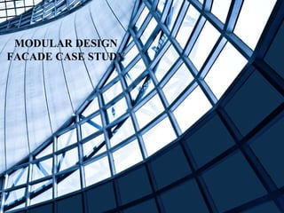
- 1. MODULAR DESIGN FACADE CASE STUDY
- 2. Multi-functional Sports Hall, Cluj Napoca
- 3. INTRODUCTION ⮚ In 2010 the local authorities of the city Cluj Napoca launched the selection process based on a Feasibility Study for the new Multi-functional Sports Hall, located near the new city stadium. ⮚ Following the selection process which included a new structural solution proposal, a designer association was selected including architects, structural engineers and electrical engineers. ⮚ Based on a new structural concept, Plan 31 Ro Ltd. was elected for designing the building structure. The technical solution regarding force resisting structure was decided after taking in consideration a couple of monolithically concrete frames and a roof made out of laminated wooden arches. ⮚ The monolithic concrete had the disadvantage of reduced time efficiency, and after the future owner decided that it would be better to reduce the time with execution from 36 months to 12 months in order to be able to organize a European Sport Competition, the design team had to find new solutions.
- 4. ⮚ The building has 115m x 130m in plane dimensions, the work on site needed to start 2 months before winter time (often the air temperature is below -4 degrees Celsius) came with many restrictions regarding pouring in situ concrete. ⮚ The surface concrete slab of 15,000sqm have arisen the cracking issue due to concrete shrinkage after its hardening, so the decision was a widespread use of precast concrete elements. ⮚ Where the design loads resulted in great reaction forces there were used prestressed concrete beams with cast in situ concrete columns, while for the rest of the elements were pre-casted and fixed with dry or wet connections. ⮚ The 64m span roof was first thought to be designed as several laminated wooden arches. Do to the fact the entrepreneur have neither the possibility nor the technology to build these type of elements, a new solution was brought and that was a space truss with Square hollow sections(SHS).
- 5. ⮚ The new multifunctional sports hall is the newest public facility for training, championships and cultural events, in a building conceived to be part of an ensemble together with Cluj Arena, the football and athletics stadium also designed by Dico and Tiganas and opened in 2011. ⮚ The envelope of the building is a simple box, surrounding another box which contains the main hall, providing 7000 seats and holding up to 10000 people for concerts. ⮚ The façade is an assembly of layers, whereby the outer layer is a mesh of parametrically distorted rectangles inspired by the nets used in several ball sports. ⮚ The perforated steel plates form 3D pyramids that reflect the sky and the sun from different angles and provide colorful effects. ⮚ The main hall is a stage and a backstage at the same time, bringing together the public and the performers inside a black box, in which all equipment is located, but camouflaged. From shining white with golden accents to a dark grey and black ambience, from outside to inside and vice versa, the architecture is composed of light and color.
- 6. PLAN ⮚ There are entries to the hall from all sides as the footfall requires multiple entrances. ⮚ The staircase at the corners are the emergency staircase for exit in case of fire. ⮚ On the ground floor there are two open spaces one is practice court and other is open ground for multiple sports. ⮚ The building has 115m x 130m in plane dimensions. ⮚ The capacity of hall is of 7000 seats. ⮚ The truss has a clear span of 63.90m, a total length of 76.10m. N Staircase Entrance
- 7. GROUND FLOOR VIEWS GROUND FLOOR LOBBY ENTRANCE CORRIDOOR ENTRANCE AREA PRACTICE AREA MAIN HALL
- 8. FIRST FLOOR PLAN ⮚ The first floor consists of toilets and staircases for the spectators. ⮚ There are 6 staircases which connects the first floor to the second floor. ⮚ It is a building conceived to be part of an ensemble together with Cluj Arena, the soccer and athletics stadium. ⮚ The building has a permanent dialogue with the people from the street through the challenge to read the geometry of the facades, being the same time introverted. Staircase
- 9. FIRST FLOOR VIEWS VIP SPECTATORS LOBBY STAIRCASE TOWARDS FIRST FLOOR MAIN HALL VIEW TOILET AREA
- 10. SUBSTRUCTURE ⮚ The substructure consists mainly in pad foundations strip foundations were used for the walls situated at the underground level, while for the training room a raft foundation was chosen being also the support of the boarded floor. ⮚ Moment resisting beams were added where it was necessary to balance the pad foundations due to the large bending moments appeared at the base of the concrete columns supporting the roof. ⮚ The building is a concrete frame structure with a characteristic bay of 8.40x10.60m, for the arena area. On sides the bays are smaller and with varying dimensions. ⮚ The concrete frames consist in precast concrete columns fixed in foundations using dry connections. ⮚ The columns supporting the steel roof which are cast in situ. PRECAST COLUMN BASE CONNECTION
- 11. ⮚ All frame beams and stair beams are precasted, reinforced concrete or prestressed concrete. ⮚ The beam-column joints are moment-resisting and pinned for the upper levels. The frames are connected directly to the roof`s steel truss. ⮚ Rigid connections have been used for the beams which are in the same plane with the space truss. BEAM COLUMN CONNECTION Before Connecting After Connecting ⮚ The slab consists in a precast part of hollow-core units with 200mm and 320mm height or preslabs of 80mm thick where the slab span is reduced and a topping of 80mm thickness of C25/30 concrete, and S500 reinforcing steel. ⮚ For a better connection between the partially precast slab and the beams, hollow-core units were partially cut off at the edges and extra reinforced with triangular skeleton reinforcing. ⮚ The meshing wires in the topping were enough for the connectors left out of the preslabs surface. Slab Reinforcement
- 12. SECTIONS :- 1. In the section shown here, Multi-functional Sports Hall is organized on five levels: underground level, ground level and three stories. 2. Underground level is a parking with 447 car capacity. 3. Ground level together with first and second level includes public, officials, media, shopping and administration areas. 4. The third level is for media, special equipment and installations devices. 5. In order to offer multiple use of the playing area- 6. The floor surface can be changed from 30x47m to 38x56m by using extensible/retractable tribune structure on the ground level.
- 13. Design of roof steel structure :- ⮚ The roof structure consists in 7 trusses with a clear span of 63,90m, and total length of 76,10m, supported by concrete frames and lateral interconnected with the rest of the structure through horizontal and vertical steel bracings. ⮚ The space steel trusses are mounted using a spacing of 10,50m. ⮚ The truss section is 3600 mm wide and approximately 4000 mm deep. ⮚ The steel trusses of this size are able to span such distances as simply supported elements, but large vertical deformations and horizontal reactions were necessary to be managed. Several options were investigated to keep the sizes to a minimum, including arch action have and cantilevered truss structure . ⮚ The system that was decided combines both: the advantage of this system is that the end cantilever with the vertical tying elements of the truss effectively reduces the vertical deformations and axial forces in mid span, as well as allowing the continuity of the roof structure over the lateral annexes. ⮚ Longitudinal trusses were placed in mid span, at the supports and near the supports, where the inner flange of the truss compression effort change in tension.
- 14. Design of roof steel structure :- ⮚ An transverse truss is cooperating with a first and a second longitudinally extending beam of a building structure. ⮚ The transverse trust comprises a lower transverse member. A first and a second truss portion is secured to a first and a second end of the lower transverse member. ⮚ A first and a second upstanding member are secured to the lower transverse member adjacent to the first and second truss portions for defining a first and a second slot there between. THE STRUCTURE MODEL OF TRANSVERSE FRAME
- 15. Design of roof steel structure- joints ⮚ Providing pinned supports for the roof trusses, positive effects in the internal effort distribution and the highest horizontal reaction over the concrete structures, were obtained. ⮚ The use of simply supports for the roof trusses eliminates the horizontal reaction over the concrete structure, but has a negative influence over the roof trusses in terms of vertical deflection and effort distribution. SLIDING POSSIBILITY OF SUPPORT AND LATERAL VIEW OF SUPPORT LEVEL
- 16. Design of roof steel structure-truss ⮚ According to the buckling analysis, a very similar buckling shape and the associated critical load multiplication COMPRESSED DIAGONAL BUCKLING IN SPACE TRUSS
- 17. Design of roof steel structure-truss ⮚ Joints are checked using FEM of steel truss- ⮚ What is FEM? -The finite element method (FEM) is a widely used method for numerically solving differential equations arising in engineering and mathematical modeling. Typical problem areas of interest include the traditional fields of structural analysis, heat transfer, fluid flow, mass transport, and electromagnetic potential. ⮚ According to the analysis results, the local stability loss of the compressed diagonal members connected in the joint will define the joint capacity. ANALYZED TRUSS JOINT
- 18. DESIGN OF ROOF STEEL STRUCTURE-TRUSS FEM OF THE SELECTED JOINT AND MATERIAL MODEL FIRST BUCKLING MODEL OF THE JOINT ANALYSIS RESULT WITHOUT BUCKLING
- 19. Design of roof steel structure-truss erection ⮚ The structure erection stages are: ⮚ - Phase I – cast in situ columns together with the precast elements (columns, beams, slabs) are erected till the roof level, while the area beneath the playing field remains at the foundation stage in order to be able to accomplish later the steel roof structure from inside and from outside the building perimeter ⮚ Phase II – erecting work of the space steel trusses and mounting the bracings ⮚ Phase III – mounting the precast elements ⮚ Phase IV – installation of the roof and façade envelope. ⮚ The structure is beenm cut in five pieces ⮚ Due to the expensive transportation of the first truss, for the next six only the assembly parts were cut in the shop, the truss assembly welding was switched on site. ⮚ In the erection phase the end parts was positioned first, followed by the intermediate three subassemblies positioning as a single one. TRUSS SPLICING FOR TRANSPORT AND ERECTION ON SITE
- 20. 3D MODEL
- 21. ELEVATIONS ⮚ The facade is an assemblage of layers reflecting and transmitting the light into the foyers inside. The outer mask is mesh of parametrically distorted rectangles inspired by the nets used in several ball sports. Front Elevation Back Elevation South Side Elevation North Side Elevation
- 22. ⮚ The perforated steel plates are forming 3D pyramids reflecting the sky and the sun at every time in different angles and colored effects. The building has a permanent dialogue with the people from the street through the challenge to read the geometry of the facades.
- 23. CONCLUSION : 1. The above information gives us a detailed analysis of the multi-functional sports hall in Cluj Napoca . 2. The plan provides us information about how the spaces in the hall are managed and segregated. 3. We also come to know about the structural details and construction process and finally we focus on our main point i.e Design of roof steel structure. 4. The use of precast members like beams and columns can be seen in the overall structure. 5. The connections details of the precast members are also studied. 6. The section transverse truss and its model with joinery details are provided with steps of assembling huge truss.