
Recommended
Recommended
More Related Content
What's hot
What's hot (20)
Similar to 2003v12 building tension
Similar to 2003v12 building tension (20)
More from HugoCopire1
Recently uploaded
Recently uploaded (20)
2003v12 building tension
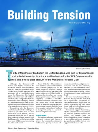
- 1. Building Tension Martin Simpson and Mike King Although the Commonwealth Games were highly successful, the 41,000-seat stadium could never be vi- able as a track-and-field venue alone. The key to its ongoing success was its permanent role as a world-class soccer venue for Manchester City Football Club, with a temporary role mid-con- struction as the focal point of the Com- monwealth Games. The legacy it leaves is a landmark building of iconic architec- ture and a stimulus for the gentrification of an underdeveloped sector of the city. Immediately after the Common- wealth Games finished, work began in earnest to convert the track and field venue to a soccer stadium. This in- volved excavating the area of the ath- letic track to 6 m below ground level, building another level of terraces at the new, lower field level, and constructing the entire north stand. Soccer fields have different dimen- sions from track venues, and spectators have different perspectives in the sports’ respective stadiums. Modern soccer stadiums require spectators to be seated as close to the field as possible to maximize the atmosphere and provide the best possible views. A track is much larger than a soccer field, so if the Man- chester Stadium were to remain a duel- use venue, then soccer spectators would be seated far from the field. Per- manent, dual-purpose facilities have been adopted in a number of stadiums in Europe, but quality as a soccer sta- dium is compromised heavily. STRUCTURE The stadium is formed from several structural systems, each chosen to achieve the structural performance, architectural quality and cost effi- ciency. Concrete frame and precast ter- race units form the bowl structure, while the roof was formed from struc- tural steel rafters suspended from an innovative cable-net structure. This ar- ticle discusses the steel roof in more detail. The most visible features of the sta- dium are the 12 perimeter masts that rise as high as 70 m (230’) into the air. Each of these masts is supported at the base by either a concrete plant tower linked back to the bowl structure, or from a plinth at ground level. These masts support the cable net, which is formed from forestay cables to the roof and backstay cables to the ground. The forestay cables are grouped together in fans of either five or seven cables, and formed from a sin- gle, spiral-strand cable, which in turn supports an individual rafter. Modern Steel Construction • December 2003 © Dennis GilbertVIEW The City of Manchester Stadium in the United Kingdom was built for two purposes: to provide both the centerpiece track and field venue for the XVII Commonwealth Games, and a world-class stadium for the Manchester Football Club.
- 2. December 2003 • Modern Steel Construction At each mast head, the tension forces of a forestay group are trans- ferred into compression in the masts and tension in a pair of backstays. Each of the backstays in the pair comprise four, grade 460 N/mm2 (67 ksi) “Macalloy” rods anchored to the ground with multi-strand ground an- chors pre-compressing concrete piles. The cigar-shaped masts take the re- solved compression force from the forestay and backstay cable tensions. They are fabricated from curved steel plate. The cigar profile is achieved by constructing each mast of a cylindrical central piece and two conical end pieces. The central sections range in di- ameter from 1500 mm (59”) for the four side masts and 1300 mm (51”) for the four end masts and four corner masts. All masts taper to 750 mm (30”) diame- ter at the lower ends and 650 mm (26”) diameter at the mast heads, with wall thicknesses between 20 mm and 30 mm (0.8” and 1.2”). ROOF UPLIFT As with all lightweight roofs, wind- induced uplift was one of the most sig- nificant design criteria. There are sev- eral solutions for maintaining tension in cables under uplift, including in- creasing the mass of the roof by addi- tional ballast or using opposing cables with tension and compression rings. Program and budget constraints forced the designers to explore an alternative solution. The stadium uses a method called “the grounded tension ring,” an inno- vative adaptation of the opposing cable solution. A “catenary cable” links all the forestays together. At each corner of the stadium this catenary cable is tied back to the ground by four “corner tie cables.” By pulling down at the four corners a tensile force can be induced into the entire cable net. The geometry of the cable net was defined in such a way that this pretension force was ex- actly equal to the force induced in the forestay cables under the worst-case wind-uplift condition. Therefore the cables do not go slack under any wind- Three of the permanent stands were constructed in a horseshoe arrangement along with their associated roofs for the stadium’s mid-con- struction role in the Commonwealth Games. Photo © Dennis GilbertVIEW The most visible features of the stadium are the 12 support masts (shown in blue, above).Tensile forces are maintained in the cable net under all loading conditions.
- 3. uplift situation. The software used for the structural analysis of the roof, in- cluding the form-finding and non-lin- ear analysis (static P-delta and dynamic relaxation) was Oasys GSA. Oasys GSA is written by Arup for in- ternal use, but is also available exter- nally as commercial software. The geometry of the cable net used for the stadium is such that it can form an independent, statically determinate structure under pre-stress, with just the cables and the masts. As a result, it could be erected independently of the rafters. The use of the grounded ten- sion-ring cable net meant the roof could be installed in two distinct phases. For the Commonwealth Games, three of the permanent stands were constructed in a horseshoe arrangement along with their associ- ated roofs. These gave a homogeneous look to the stadium even though it was only partially complete. The final per- manent stand and the final portion of the roof were erected during phase two for the soccer conversion. ROOF GRAVITY LOADS The load path for downwards loads can be idealized as a standard triangu- lated system, with most loads apart from self weight applied directly to the cladding. There are two distinct types of cladding: ● Standing-seam aluminium cladding (Kalzip) to the majority of the roof. ● Transparent polycarbonate to the leading edge. This transparent zone increased the amount of natural light entering the bowl, which im- proved the environment in the sta- dium for players, spectators and television coverage, in addition to assisting grass growth of the natural field. The standing-seam cladding is sup- ported directly from structural liner trays that span approximately 4 m (13’) between wide-flange purlins. The purlins in turn span between the 76 rafters that run in a radial pattern. The rafters are fabricated steel box sections, 900 mm deep by 300 mm wide (35” by 12”), tapering to 450 mm deep (18”) at the leading end and rear end. The flanges of the box sections vary be- tween 12 mm and 55 mm (0.5” and 2.2”) and are optimized to provide greatest efficiency. The webs of the box section are constant at 6 mm (1 /4”) thick. Each rafter is supported at two points: ● At the rear of the stadium, each rafter is supported from the con- crete bowl by an integral “V strut” formed by two inclined struts of cir- cular HSS. ● Towards the leading edge, the rafter is effectively hung from the cable net by means of the “Forestay- strut.” The maximum rafter cantilever is 15 m (49’), and the back span of a rafter is 37 m (121’). This ratio was derived to equate the back-span and cantilever moments for the longest rafter under a variety of load cases, and to optimize the rafter design. The geometry of back span to cantilever for other rafters then was dictated by the geometry of the cable net. DESIGN OF ROOF PLATE The roof has a saddle profile due to the constraints of the bowl geometry. A roof with a curving profile can be sub- jected to arching in the roof plate. For the stadium, the occurrence of arching was not desired as it tries to short-cir- cuit the primary load paths through the cable net. This secondary load path was also a problem for thermal expan- sion and would have required a signif- icant increase in the size of the purlins to facilitate it. One solution would be to allow movement joints at the four cor- ners to coincide with the major thermal joints in the concrete bowl. However, waterproofing details at movement joints are notoriously difficult and ex- pensive, so the design team adopted a solution of regular but much smaller movement joints throughout the roof. These joints were incorporated every other bay through simple slotted holes in the purlins and shoulder bolts. The movements at each joint were in the order of 25 mm (1”), which the stan- dard cladding and flashing details could accommodate. The lateral stabil- ity of the rafter was provided by cross- bracing every other bay. Lateral-torsional stability and minor-axis buckling of the rafter was also a key factor in the design, espe- cially under wind-uplift conditions where effective restraint from the purlins could not be provided. The so- lution was to use U-frame stability, more commonly associated with bridge design. By using internal di- aphragms within the box-section rafters at the purlin positions, the bending resistance of the purlin could restrain the bottom flange of the rafter. DESIGN OF THE STADIUM ROOF UNDER SERVICE CONDITIONS The assessment of the roof in service was one of the most complex elements of the roof design. At the time of the as- sessment into behavior of the roof under service conditions, it was still the intention to use laminated glass as the cladding to the leading edge in place of polycarbonate cladding. The use of glass in such a roof imposed strict lim- its as to acceptable deformations. The behavior of the roof was assessed for the following criteria: Drainage Slope—The only gutter is located at the rear edge of the roof. All water should flow to the outside of the stadium to prevent ponding or water running off the leading edge. Each rafter and cladding panel was assessed to ensure that there was always a posi- tive fall of 1.5° under all service-load conditions. Visual Deformation—The visual performance of the rafters was main- tained at 1:100 for the cantilever and 1:200 for the back spans. However the overall total deflection was controlled by the deflection of the cable net, which was also limited to 1:100. Shear Strain and Warping—The shear strain was measured as the change in angle at the four corners of a cladding panel, and the warping was measured as the mean change in dis- tance out of plane at each of the four corners. These criteria were assessed for every cladding panel. Movement—The length of slots cut in the purlins to allow movement was assessed for various load cases and studies were carried out to determine the effect of the movement joints seiz- ing up. Though each of the rafters are sup- ported by a forestay, the forestays themselves are grouped together in ‘fans’ supported by single masts. De- flection in the rafters is controlled largely by rigid body rotation caused by extension of the backstays and rota- tion of the masts and rafters. If an indi- vidual rafter is loaded heavily then the subsequent rotation of the mast also will lower all the rafters attached to Modern Steel Construction • December 2003
- 4. that mast. Therefore the forestay cable fans act as load-sharing devices with respect to relative displacement be- tween rafters. DESIGNING FOR ROBUSTNESS Blast protection is important for sta- diums, where roofs cover thousands of spectators. The robustness require- ments of this stadium were investi- gated thoroughly leading to the use of multiple cables for highly sensitive load paths. ● Each backstay is made from four el- ements, which in turn are attached to two discrete foundation plinths. ● Each catenary cable and corner tie is made from four cables. ● Non-linear studies were carried out to investigate the results of losses of elements ranging from forestay ca- bles to entire towers. Under extreme emergency-load cases, stability of the four cable ele- ments is maintained with any three re- maining cables from the group of four. In addition, the primary connections involving multiple cables, i.e. the mast heads, were designed taking into ac- count the eccentricities caused by los- ing one or more forestay or backstay cables. The conclusion was that there is a sufficient degree of redundancy in the load paths, which will avoid dis- proportionate collapse under most con- ceivable extreme-loading conditions. Fire protection is provided inher- ently to the bowl, due to the use of re- inforced concrete. The roof structure is not fire-protected, as there is negligible combustible material in the terrace area. Most importantly, the roof is not required for the stability of the stadium bowl. ROOF CONSTRUCTION SEQUENCE Arup’s original erection proposal took advantage of the mast and cable- net structure’s independence from the roof steel structure by erecting and pre- tensioning the cable-net prior to the lifting and attachment of rafter and purlin braced pairs. Due to program constraints, it was decided to bring for- ward the erection of roof plane steel- work so that it could be erected in parallel with the lifting of masts and as- sembly and stressing of the cable-net. The end result was a framework of temporary steel props erected to sup- port the leading edge of the rafters. The revised erection scheme created a platform at roof level on which the cable-net could be laid out prior to final assembly and stressing. Once erection of the masts and assembly of the cable- net was complete, the cable-net was made taut by pulling down on the backstays and connecting them to their pinned bases. The final tension was ac- complished by jacking the four corner ties at the top of the corner-tie frames. Upon completion of the stressing phase, individual rafters were lifted off their props and connected to the cable- net, after which the temporary props were removed. During the conversion of the sta- dium for soccer use, the roof of the north stand was completed as origi- nally intended. The cable net was in place from phase one and each roof panel was lifted into position and sup- ported from the rear of the bowl and hung from the cable net. This phase of the works was carried out successfully to a very tight schedule. CONCLUSION The successful design of the cable- stayed roof for the City of Manchester Stadium can largely be attributed to the teamwork between the structural engi- neers, architects and steelwork fabrica- tors. The roof is a ground-breaking structure, incorporating many innova- tive features that are sure to be re- peated on future stadium projects around the world, especially the first use of the grounded tension ring phi- losophy. REFERENCE Simpson, M. “The Analysis and Design of the City of Manchester Stadium.” Proceedings of the Fifth International Conference on Space Structures, Sur- rey, 2003, pp 827-836. OWNER Manchester City Council OPERATOR Manchester City Football Club ARCHITECT AND STRUCTURAL ENGINEERS Arup Associates, London CONSTRUCTION MANAGER Laing O’Rourke, Kent, UK ENGINEERING SOFTWARE Oasys GSA The Manchester Stadium in its final configuration as a soccer venue. Photo courtesy Lee Jordan. December 2003 • Modern Steel Construction