Management of Power System Dynamic Security
•
0 likes•137 views

Management of Power System Dynamic Security
![To increase situational awareness of dispatchers the task force investigating the 2003 U.S.-Canada blackout
suggests the use of real-time dynamic security assessment. Dynamic security assessment (DSA) includes
methods to evaluate stability and quality of system transition from a pre- to post-disturbance state. Similar
directives have also been released by the European Network of Transmission System Operators for Electricity
(ENTSO-E). One of the ENTSO-E appeals concerning the future network development is that tools to assess the
dynamic security of the pan-European electrical network should be developed to minimize the probability of
operational irregularities. These tools should primarily rely on the well established computational techniques
enabling ‘What if’ analysis and assessment of the distance to the system security limits [1].
In this paper a research oriented prototype of a tool for DSA is presented, capable of analyzing system dynamic
performance by making use of so-called performance indices. The tool is a result of a research work carried out
by international team of experts from University of Ljubljana, Slovenia, electric companies headquartered in
various European countries and SIEMENS AG, Germany. The task of the university was to explore and develop
DSA methods under constraints of practical applications, whereas the technical advisors from the industry
provided expert knowledge from experiences. The aim of the tool is to help managing power system stability
problems by alerting the control operator to conditions that represent a significant risk to system security and
providing practical information for decision making.
2 Analysis in System Operations
While it is true that power systems are designed to be stable, in actual practice, systems may be prone to being
unstable. This is largely due to uncertainties related to assumptions made during the design process. For example,
when designing a system its stability and limits of secure operation are usually determined under some assumed
load levels, generation, topology structure, etc. But the fact is that in many power systems such principal
assumptions strongly deviate from the actual circumstances.
To deal with the unpredictability of operations, especially in the systems with a significant share of dispersed
generation, it is necessary to perform on-line security investigations. The main issue is a classification problem:
given a present operating point and a single or multiple contingencies (outage of transmission elements, sudden
loss of wind power, faults, etc.) the system analysts determines, on-line, if the situation is secure or insecure,
regarding the contingencies. The weak points are identified for the existent condition and by preventive control
the security of the system can be maintained on the required level. The investigation can be conducted at regular
intervals e.g. generator dispatch cycle or on demand. In any case, the power flow is derived from real time data
and is together with other required data required for calculations passed to DSA software residing on dedicated
computers. The security of the system is assessed against criteria, typically including:
• rotor angle stability, voltage stability, frequency stability,
• frequency excursions during the dynamic state (dip or rise) beyond specified threshold levels,
• voltage excursions during the dynamic state (dip or rise) beyond specified threshold levels,
• damping of power swings inside subsystems and between subsystems on an interconnected network.
A flow chart of the generalized DSA process is illustrated in Figure 2. Such a process can be conveniently
incorporated into existing configuration of an operational control room. Experiences of the control operators
relying on the on-line investigations in daily operations are reported in [2]-[4]. The solutions they use help them
to quickly assess a potentially rapidly changing system state and to formulate corrective control actions in real
time.](data:image/gif;base64,R0lGODlhAQABAIAAAAAAAP///yH5BAEAAAAALAAAAAABAAEAAAIBRAA7)
Recommended
More Related Content
What's hot
What's hot (20)
Similar to Management of Power System Dynamic Security
Similar to Management of Power System Dynamic Security (20)
More from Power System Operation
More from Power System Operation (20)
Recently uploaded
Recently uploaded (20)
Management of Power System Dynamic Security
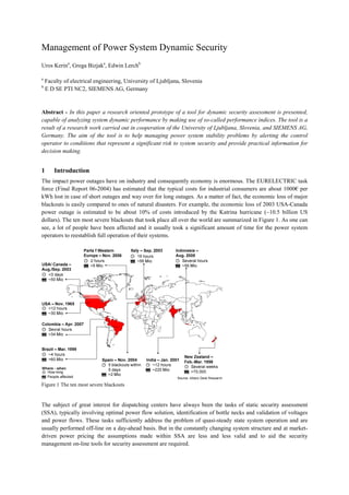
- 1. Management of Power System Dynamic Security Uros Kerina , Grega Bizjaka , Edwin Lerchb a Faculty of electrical engineering, University of Ljubljana, Slovenia b E D SE PTI NC2, SIEMENS AG, Germany Abstract - In this paper a research oriented prototype of a tool for dynamic security assessment is presented, capable of analyzing system dynamic performance by making use of so-called performance indices. The tool is a result of a research work carried out in cooperation of the University of Ljubljana, Slovenia, and SIEMENS AG, Germany. The aim of the tool is to help managing power system stability problems by alerting the control operator to conditions that represent a significant risk to system security and provide practical information for decision making. 1 Introduction The impact power outages have on industry and consequently economy is enormous. The EURELECTRIC task force (Final Report 06-2004) has estimated that the typical costs for industrial consumers are about 1000€ per kWh lost in case of short outages and way over for long outages. As a matter of fact, the economic loss of major blackouts is easily compared to ones of natural disasters. For example, the economic loss of 2003 USA-Canada power outage is estimated to be about 10% of costs introduced by the Katrina hurricane (~10.5 billion US dollars). The ten most severe blackouts that took place all over the world are summarized in Figure 1. As one can see, a lot of people have been affected and it usually took a significant amount of time for the power system operators to reestablish full operation of their systems. Figure 1 The ten most severe blackouts The subject of great interest for dispatching centers have always been the tasks of static security assessment (SSA), typically involving optimal power flow solution, identification of bottle necks and validation of voltages and power flows. These tasks sufficiently address the problem of quasi-steady state system operation and are usually performed off-line on a day-ahead basis. But in the constantly changing system structure and at market- driven power pricing the assumptions made within SSA are less and less valid and to aid the security management on-line tools for security assessment are required.
- 2. To increase situational awareness of dispatchers the task force investigating the 2003 U.S.-Canada blackout suggests the use of real-time dynamic security assessment. Dynamic security assessment (DSA) includes methods to evaluate stability and quality of system transition from a pre- to post-disturbance state. Similar directives have also been released by the European Network of Transmission System Operators for Electricity (ENTSO-E). One of the ENTSO-E appeals concerning the future network development is that tools to assess the dynamic security of the pan-European electrical network should be developed to minimize the probability of operational irregularities. These tools should primarily rely on the well established computational techniques enabling ‘What if’ analysis and assessment of the distance to the system security limits [1]. In this paper a research oriented prototype of a tool for DSA is presented, capable of analyzing system dynamic performance by making use of so-called performance indices. The tool is a result of a research work carried out by international team of experts from University of Ljubljana, Slovenia, electric companies headquartered in various European countries and SIEMENS AG, Germany. The task of the university was to explore and develop DSA methods under constraints of practical applications, whereas the technical advisors from the industry provided expert knowledge from experiences. The aim of the tool is to help managing power system stability problems by alerting the control operator to conditions that represent a significant risk to system security and providing practical information for decision making. 2 Analysis in System Operations While it is true that power systems are designed to be stable, in actual practice, systems may be prone to being unstable. This is largely due to uncertainties related to assumptions made during the design process. For example, when designing a system its stability and limits of secure operation are usually determined under some assumed load levels, generation, topology structure, etc. But the fact is that in many power systems such principal assumptions strongly deviate from the actual circumstances. To deal with the unpredictability of operations, especially in the systems with a significant share of dispersed generation, it is necessary to perform on-line security investigations. The main issue is a classification problem: given a present operating point and a single or multiple contingencies (outage of transmission elements, sudden loss of wind power, faults, etc.) the system analysts determines, on-line, if the situation is secure or insecure, regarding the contingencies. The weak points are identified for the existent condition and by preventive control the security of the system can be maintained on the required level. The investigation can be conducted at regular intervals e.g. generator dispatch cycle or on demand. In any case, the power flow is derived from real time data and is together with other required data required for calculations passed to DSA software residing on dedicated computers. The security of the system is assessed against criteria, typically including: • rotor angle stability, voltage stability, frequency stability, • frequency excursions during the dynamic state (dip or rise) beyond specified threshold levels, • voltage excursions during the dynamic state (dip or rise) beyond specified threshold levels, • damping of power swings inside subsystems and between subsystems on an interconnected network. A flow chart of the generalized DSA process is illustrated in Figure 2. Such a process can be conveniently incorporated into existing configuration of an operational control room. Experiences of the control operators relying on the on-line investigations in daily operations are reported in [2]-[4]. The solutions they use help them to quickly assess a potentially rapidly changing system state and to formulate corrective control actions in real time.
- 3. Figure 2 Flow chart of an on-line DSA process 3 Dynamic Security Inference Two approaches may be used regarding the system state classification: direct classification of the operating state or inference of the value of important variable or some index, then used for classification. In the direct approach, the system analyst carries out full simulation and dynamic performance of the system is validated against allowable limits through application of the system’s model. Concerning the security a yes-or-no answer is provided. An answer like this is may be used for classification of system states in absolute terms (secure - insecure), however in marginal situations, where the operating point is still designated as secure, but is very close to limits, it can lead to inadequate decision making and ultimately operator performance errors. The other possibility is to use so-called performance indices. These indices refer to values of system parameters which vary significantly with the prevailing conditions in the system. There are many important parameters of which dynamic response can be used for establishing contingency severity levels as a measure of power system security. Some important ones are rotor angle of system generators, frequency, voltage, and damping of oscillations. Figure 3 suggests that it is crucial to keep these parameters within limits continually otherwise the system may undergo stability problems. Figure 3 Region of secure system operation 3.1 Indices for evaluation The DSA solution presented in this paper is based on inference of 18 complementary security indices, capable of capturing the dynamic state of the power system during and after contingencies. Each of these indices captures a single security aspect and in combination with the others leads to a more accurate contingency evaluation scheme. The indices are able to estimate consequences on the system, such as overloading of transmission elements, relays operation, angle stability loss, voltage drop, etc. Their exact definitions and argumentation are available in [5]-[7]. Every single index is a well-thought relation between the actual and maximum acceptable
- 4. value of an observed system parameter. A general index form is given by equation 1, where x is the actual (temporary) value of the system parameter during and after a contingency and y is its corresponding acceptable value. Note that by using this approach all the security issues are normalized and can be compared to each other. The output range of the indices is between 0 and 1. min 1,max x index y = (1) The temporary values over time may be obtained by measurement or simulation, for evaluation of existent or future system states respectively. The maximum acceptable values of system state variables are usually enforced through the grid code. For example, grid codes issued during the last years have invariably demanded that wind farms must withstand voltage dips to a certain percentage of the nominal voltage and for a specified duration. Such requirements are known as Fault Ride Through (FRT) and are described by a voltage vs. time characteristic (Figure 4). Figure 4 FRT curve for high and extra high voltage levels (EON Germany) The FRT requirements imply that the voltage at the generator connecting nodes needs to be observed at any instant. For that purpose the Voltage Ride Through Index (VRTI) is proposed. The index monitors the voltage behavior and delivers the relative agreement between the actual and limiting voltage pattern after disturbances. It reports whether a disturbance would cause a generator to trip and gives the security margin to a disconnection. The index is given by definitions (2)-(4) and considers a transient voltage dip both in percentage deviation and in time duration; the fault-on and post-fault voltage dynamics is taken into account by comparing the surface captured by the voltage deviation (with respect to the normal voltage band) with the reference surface specified by the transient time and voltage limits. For the sake of evaluation, the reference surface can be treated as one or divided into a number of segments. So, each stage of the voltage transient can be evaluated regarding the corresponding limits; good results are obtained if two areas are defined: one for the fault-on and the other for the post-fault period (Figure 5).
- 5. Figure 5 Areas for determining fault impact on generator connecting nodes max min 1,max A area j area j i t area j adm V dt VRTI ∆ ⋅ = ∫ (2) min min min min min , if V , if < V 0 , if V area j i adm area j band area j band i adm i adm i adm band i adm V V V V V V V ∞ < ∆ = − < ≥ (3) ( )max min maxA tarea j area j area j adm n adm admV V= − ⋅ (4) In the expressions, the superscript denotes j-th reference area for the evaluation, which is given by the maximum admissible time of i-th node voltage for being at its minimum admissible value. The list of all indices proposed for security inference is given in table 1. Four deliver degree of dynamic security on system-level; six are for quantifying variations in dynamic security on element-level, whereas eight are for evaluation of post-contingency steady state condition. Table 1 Proposed power system security indices System Indices Dynamic Indices Quasi-Steady State Indices Small Signal Stability Index SSSI Angle Index AI Quasi Stationery Voltage Index QSVI Energy Margin Index EMI Dynamic Voltage Index DVI Line Power Flow Index LPFI Voltage Collapse Index VCI Voltage Ride Through Index VRTI Transformer Power Flow Index TPFI Protection Security Index PSI Frequency Recovery Time Index FRTI Load Shedding Index LSI Frequency Gradient Index FGI Nodal Loading Index NLI Maximum Frequency Deviation Index MFDI Thevenin Index THI Approximated Voltage Index APVI Under Over Voltage Index UOVI 3.2 Composite Index Experience from the development of an on-line implementation contingency screening and ranking in static security assessment suggests that:
- 6. • no single security index can reliably capture the entire system state; • a combination of complementary indices can be used to reliably rank and select contingencies while each of individual indices may not give enough information for a 100% accurate ranking. One way to combine the individual indices into a composite index in dynamic security assessment is to calculate a weighted sum. This approach has been extensively used by many experts (e.g. see [8]). The weighted-sum technique is simple to understand and easy to implement; but it has two main shortcomings: often the optimal solution distribution is not uniform, and more seriously, the technique is often implemented as a convex combination of objectives, where the sum of all weights is constant and negative weights are not allowed, thus wrong choice of weights may result in selection of an inferior solution by missing important solutions in the non- convex regions. An alternative to the weighted-sum method is a technique coming from soft computing. Assuming that the system analyst is able to represent its knowledge about the system as a set of facts and rules, the uncertainties related to proper weight selection and formation of the composite index can be more efficiently handled by means of fuzzy logic. Fuzzy logic is considered as a very important tool of artificial intelligence which could be used in various fields of human decision support systems. Its capabilities have been proved by many practical applications. In this work it is used as a methodology for composing of the composite dynamic security index. The main components of a three stage Fuzzy Inference System (FIS) that is used for that purpose are shown in Figure 6. The figure shows, the system is suitable for implementation into an existing environment in a control room, defined by data sources, including system state estimator, SCADA system and PMUs, on one side, and system control assets on the other. To take the advantage of the data delivered by the synchrophasors is in particular important since these devices are considered one of the most important measuring devices in the future of power systems. In the figure, the abbreviations FFI, FVI, FPI, FSI and FDSI stand for Fuzzy Frequency Index, Fuzzy Voltage Index, Fuzzy Performance Index, Fuzzy Stability Index and Fuzzy Dynamic Security Index respectively. SSSI AI EMI VCI FSI FPI FDSI PSI FVI UOVI APVI VRTI QSVI DVI LPFI LSI TPFI NLI THI FFI FGI FRTI MFDI Stability FIS (Fuzzy Inference System) Security FIS PMU (V, I - magnitude, phase angle) SCADA, disturbance recorders Voltage FIS Power Flow FIS Frequency FIS Trend analysis / Pattern recognition Situation awareness Reporting and Visualization (local, web, EMS) System status bar Operator's decisions System control Figure 6 Implementation of the proposed DSA solution
- 7. 3.3 Visualization of results For visualizing dynamic security of a power system under different network states by making use of the security indices, a deliberate visualization form is introduced. It enables an overview of the security degree of a disturbed system in reference to the security threshold and a disturbance (contingency) applied. Applying a visualization technique similar as in traffic control, the proposed security indices can communicate the security degree by means of indicative colors. These need to be carefully selected in order to deliver a suggestive message; if remedial actions are needed, for example. As illustrated in Figure 7, both, a smoothly changing color scale or a limited set of colors are suitable. Figure 7 Visualizing power system security indices The selected color scale refers to an index magnitude equally distributed along the interval [0 1]. The scale-ends denote the absolute security degree: secure-insecure. Although any color scale is adequate for the purpose, the most obvious is to use green and red for denoting the absolute secure and insecure system condition and a color- mix in between for security variation. In this way, the dramatic progression of reporting is introduced, suggesting the alert level and the expected magnitude of remedial actions for improvement of the condition. A five-color color scale seems suitable for the application; it is easy to intuitively relate red, orange, yellow, dark yellow and green to SAFE, ALERT LOW, ALERT HIGH, DANGER and INSECURE condition of the power system. 4 The DSA tool By following the principles of wrapper interfacing the presented DSA solution has been upgraded to a research- oriented DSA tool. Through a Graphical User Interface (GUI) the user is able to manipulate the performance of the computational engine (PSS® NETOMAC) and algorithms for security evaluation. The GUI consists of a number of components. The main ones are: main program window, auxiliary program window and contingency builder. By using the functionalities these components offer, one can define contingencies and scenarios to be investigated, arrange settings of computations, and investigate the DSA results in a systematic way. The main program window is shown in Figure 8. Simultaneously it serves as the main management panel and results board. It contains a command menu bar, a panel that displays operations and a status bar. There are many actions available to the user. Through this window it is possible to access functionalities of contingency builder, input calculation related settings, and initiate investigations.
- 8. Figure 8 Main program window After computations have finished, the FDSI provides both color and numeric indication of the security degree in the display panel. It is shown for each contingency and has the form of a bar chart. When one clicks on one of the charts to select it a sub-window window appears containing more detailed results. The program windows are organized into a hierarchy as show in Figure 9. Figure 9 Program windows hierarchy There are two possible ways of visualizing the results; by using a dedicated GUI, where one can systematically go into details of each contingency and inspect diagrams of observed system parameters, or in a single display, such as shown in Figure 10. The matrix visualization technique allows organizing the results automatically according to a network condition, calculated security indices and color scale. The general picture of the system dynamic performance under different contingencies is immediately obtained. Rows refer to contingencies and columns to individual security indices. Visualized are the results of 6 study cases for 12 elementary indices and 6 derived ones. Note that the blank fields in the matrix indicate that a particular security index has not been included in a certain study case.
- 9. Figure 10 Matrix visualization 5 Case study and performance In order to evaluate performance capabilities of the developed tools a test is conducted. In the test a power system is assessed for dynamic security under a set of credible contingencies. The main objective is to determine total time required for carrying out the security assessment and determine if it complies with the requirements of on-line applications. A model of a medium size power system has been used in the test. It includes 119 generators, including AVRs and governors, 527 high voltage transmission lines, 261 transformers, 415 nodes and 319 loads. The system has four main voltage levels: 500-, 230-, 115-, and 69 kV. A topology of the main 500 kV and 230 kV transmission network is shown in Figure 11. Six contingencies are put under investigation: • loss of a generator in the southern part of the system (1), • loss of a large generator in the metropolitan area (2), • transient fault at 500 kV voltage level (3), • a single 230 kV line outage in south-eastern region (4), • a single 230 kV line outage in north-eastern region (5), • three phase fault and consequent loss of parallel 230 kV lines connecting central and southern region (6). Figure 11 500 kV and 230 kV network topology From the perspective of on-line tools, the performance is normally measured in terms of total time required for carrying out a task or procedure. The faster the speed of computations the better the performance is a common understanding relating to this matter. The total time for investigation of the contingency set is given in Table 2 and is 202 seconds or 3.36 minutes. Considering the typical requirements on time outlined in [3] and [4] one may suggest that the developed DSA-tool is able to deliver performance as expected from on-line tools.
- 10. Table 2 Total computational time Prepare data Execute computations Inference Total time cnt small signal dynamic transient small signal dynamic transient FIS DSA time in seconds 1 0.252 0.623 5.259 23.058 2.036 31.228 2 0.252 0.641 4.837 22.871 1.613 30.214 3 0.192 2.083 0.158 4.962 23.121 9.606 2.051 42.173 4 0.256 1.968 4.962 23.027 1.884 32.097 5 0.258 1.997 4.994 22.965 1.961 32.175 6 0.252 2.140 5.071 23.323 3.376 34.162 202.049 The total time has three components: time required for preparing input databases, computational time, and time required for fuzzy inference and construction of the single all-encompassing security index FDSI. The time to prepare input data and execute computations is further divided into three sub-components: time for small signal stability [5] and transient stability assessment [6], and time for calculating the performance indices [7]. The inference results by making use of the matrix visualization technique are shown in Figure 10. Three contingencies are classified as insecure and clearly require immediate operator’s attention whereas three are secure, but with the security margin that still implies preventive actions; given the numeric and color designation the most severe are contingencies 4 and 6. Contingency 4 involves a spontaneous loss of a single 230 kV line. The tripping causes voltage to go out of bounds and overloading of some power lines. Violated are voltage static limits and voltage dynamic constraints, which is reported by QSVI and DVI respectively, while LPFI indicates violation of static limit referring to maximum power flow through transmission lines. Consequently the derived indices FSI and FPI report insecurity, and so does the composite FDSI. The voltage diagram at critical nodes is given in Figure 12. The development of voltage instability is clearly observable. The dynamic response of generators located in a close proximity to the tripped line is shown in Figure 13. Figure 12 Voltage collapse at 115 kV nodes Figure 13 Rotor angle of nearby machines
- 11. Contingency 6 can be designated as a worst case scenario since it causes the system to break into two parts. The first part comprises of northern, eastern and central region and second part is the southern region. The first part remains stable, while the second one undergoes instability (Figure 14). Figure 15 shows voltage at two 230 kV network nodes. The voltage at node South 2 collapses, whereas it recovers at node S. West 1. Security indices indicate that the transient condition the system undergoes violates all security limits set but one; the load flow limit of high voltage transformers (refer to TPFI in Figure 10). Figure 14 Frequency at 230kV system nodes Figure 15 Voltage at 230 kV system nodes 6 Discussion and conclusion Although being at the development/test stage the proposed research-oriented DSA-tool has a great practical potential. One possibility is to use it as a self-standing supporting tool in power system operations. Suppose in the system control room there is a machine with the tool installed and the system model is updated regularly so the quasi steady state conditions as in actual network are resembled in a e.g. generator dispatch cycle. Each time a new operating point is established the operator can select a set of credible contingencies and/or scenarios and check system dynamic security under them; if insecurity is detected an alarm is raised and the operator can systematically identify sources of poor network condition and decide whether it is reasonable to change the operating point of the system and improve security or to leave it as it is and take the risk of blackout. 7 Literature [1] ENTSO-E, “Research and development plan EUROGRID 2020”, first edition, December 2009 [2] E. Lerch, O. Ruhle, D. Vickovic, “Real-Time Stability Assessment in the Control Centers of the ISO of Bosnia and Herzegovina and a National Dispatching System in North Africa”, in Proceedings of Power Systems Conference & Exposition, 15-18 March, Seattle, USA, 2009
- 12. [3] S. Boroczky, E. Gentle, “Real-Time Transient Security Assessment in Australia at NEMMCO”, in Proce. of IEEE Power Systems Conference & Exposition, 15-18 March, Seattle, 2009 [4] L.E. Arnold, J. Hajagos, ”LIPA Implementation of Real-Time Stability Monitoring in a CIM Compliant Environment“, in Proce. of Power Systems Conference & Exposition, 15-18 March, Seattle, 2009 [5] U. Kerin, E. Lerch and , G. Bizjak, 'Monitoring and Reporting of Security of Power System Low-frequency Oscillations', Electric Power Components and Systems, Vol. 38, No. 9, pp. 1047 — 1060, June 2010 [6] C.K. Tang, C.E. Graham, M. El-Kady, R.T.H. Alden, “Transient Stability Index from Conventional Time domain Simulation”, IEEE Transactions on Power Systems, Vol. 9, No. 3, [7] J.M. Gimenez and P.E. Mercado, “A new approach for power system online DSA using distributed processing and fuzzy logic”, Electric Power System Research 77, pp. 106 – 118 [8] C. Fu and A. Bose, “Contingency Ranking Based on Severity Indices in Dynamic Security Analysis”, IEEE Transactions on power systems, Vol. 14, No. 3, August 1999