
Recommended
More Related Content
What's hot
What's hot (20)
Similar to Rfid based attendance sytem
Similar to Rfid based attendance sytem (20)
Recently uploaded
Recently uploaded (20)
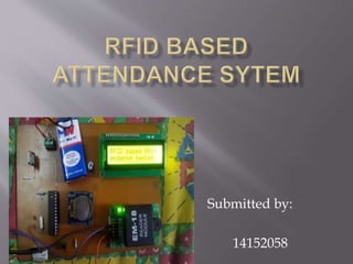
Rfid based attendance sytem
- 2. Introduction 1.What is a RFID system? Hardware requirements 1. ATMEGA 328p Microcontroller 2. EM-18 Module (RFID Reader) 3. Passive tags 4. RTC (Real Time Clock) 5. PCB 6. LCD(16*2)
- 3. List of software and tools used 1. ARDUINO IDE 2. EXPRESS PCB 3. ARDUINO UNO
- 4. RFID stands for Radio Frequency Identification. RFID is a technology which wirelessly identifies the chip or tag of interest and captures the data. It is a member of AIDC(Automatic Identification and Data) technologies. RFID system comprises of 1. RFID tags 2. RFID reader 3. RFID middleware.
- 5. RFID tags contain a wire circuit and antenna for data transmission. 1. Active 2. Passive
- 6. RFID readers are devices which emits radio signals through antennae. They also provide the necessary amount of power to the tags, if passive tags a RFID readers get the collect the data stream provided by the tags. re used.
- 7. It collects all the data that tags give, does the filtering task. RFID middleware actually is used to control and manage the RFID readers’ infrastructures. It is considered as the brain of any RFID system as it provides the most important functionalities. Some of its key functionalities are efficient management of data created by the RFID system.
- 8. 1. ATMEGA 328P Microcontroller 28-pin AVR Microcontroller Flash Program Memory: 32 kbytes EEPROM Data Memory: 1 kbytes SRAM Data Memory: 2 kbytes I/O Pins: 23 A/D Converter: 10-bit Six Channel RTC: Yes with Separate Oscillator
- 10. Operation voltage 5V DC Current of operation is less than50mA Frequency of operation: 125 KHz Distance of operation 10cm
- 11. This tiny RTC module is based on the clock chip DS1307 which supports the I2C protocol. It uses a Lithium cell battery (CR1225).
- 12. We used a 16*2 LCD means 16 columns and two rows. It has 14 pins.
- 16. Tag is detected and entry registered
- 17. Same tag detected again and exit registered