
Recommended
More Related Content
What's hot
What's hot (20)
Similar to Aircraft Anti collision system using ZIGBEE Communication
Similar to Aircraft Anti collision system using ZIGBEE Communication (20)
Recently uploaded
Recently uploaded (20)
Aircraft Anti collision system using ZIGBEE Communication
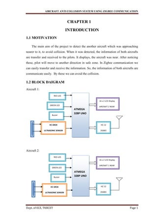
- 1. AIRCRAFT ANTI COLLISION SYSTEM USING ZIGBEE COMMUNICATION Dept. of ECE, TKRCET Page 1 CHAPTER 1 INTRODUCTION 1.1 MOTIVATION The main aim of the project to detect the another aircraft which was approaching nearer to it, to avoid collision. When it was detected, the information of both aircrafts are transfer and received to the pilots. It displays, the aircraft was near. After noticing these, pilot will move to another direction in safe zone. In Zigbee communication we can easily transfer and receive the information. So, the information of both aircrafts are communicate easily. By these we can avoid the collision. 1.2 BLOCK DAIGRAM Aircraft 1: Aircraft 2: ATMEGA 328P UNO 16 x 2 LCD Display AIRCRAFT 2 NEAR HC-12 ZIGBEE RED LED ZIGBEE GREEN LED ZIGBEE Buzzer HC-SRO4 ULTRASONIC SENSOR ATMEGA 328P UNO RED LED ZIGBEE GREEN LED ZIGBEE Buzzer HC-SRO4 ULTRASONIC SENSOR 16 x 2 LCD Display AIRCRAFT 1 NEAR HC-12 ZIGBEE
- 2. AIRCRAFT ANTI COLLISION SYSTEM USING ZIGBEE COMMUNICATION Dept. of ECE, TKRCET Page 2 1.3 LITERATURE SURVEY In this project Zigbee is placed to communicate between two aircrafts. The system is provided with Led and buzzer. If two aircrafts are moving if they are approaching near, they are detected by ultrasonic and transfer data of aircrafts by Zigbee. Once the aircraft is detected LED blinks with a buzzer sound and the data is displayed on the LCD. In this way we can detect the aircraft and can avoid the collision with the Zigbee communication. 1.4 ORGANIZATION OF THESIS In chapter 1 we are discussed about introduction of a project, in chapter 2 we are discussed about Arduino software which is used in our project, in chapter 3 we are discussed about micro controller of our project, in chapter 4 we are discussed about hardware components used in project and in chapter 5 we are discussed about final result of the project.
- 3. AIRCRAFT ANTI COLLISION SYSTEM USING ZIGBEE COMMUNICATION Dept. of ECE, TKRCET Page 3 CHAPTER 2 SOFTWARE DISCRIPTION 2.1 INTRODUCTION OF ARDUINO SOFTWARE The Arduino Uno SMD R3 is a microcontroller board based on the ATmega328. It has 14 digital input/output pins (of which 6 can be used as PWM outputs), 6 analog inputs, a 16 MHz crystal oscillator, a USB connection, a power jack, an ICSP header, and a reset button. It contains everything needed to support the microcontroller; simply connect it to a computer with a USB cable or power it with a AC-to-DC adapter or battery to get started. The Uno differs from all preceding boards in that it does not use the FTDI USB-to- serial driver chip. Additional features coming with the R3 version are: ATmega16U2 instead 8U2 as USB-to-Serial converter.1.0 pinout: added SDA and SCL pins for TWI communication placed near to the AREF pin and two other new pins placed near to the RESET pin, the IOREF that allow the shields to adapt to the voltage provided from the board and the second one is a not connected pin, that is reserved for future purposes stronger RESET circuit. "Uno" means "One" in Italian and is named to mark the upcoming release of Arduino 1.0. The Uno and version 1.0 will be the reference versions of Arduino, moving forward. The Uno is the latest in a series of USB Arduino boards, and the reference model for the Arduino platform. 2.2 PROGRAMMING The Arduino Uno can be programmed with the (Arduino Software (IDE)). Select "Arduino/Genuino Uno from the Tools > Board menu (according to the microcontroller on your board). For details, see the reference and tutorials. The ATmega328 on the Arduino Uno comes preprogrammed with a bootloader that allows you to upload new code to it without the use of an external hardware programmer. It communicates using the original STK500 protocol (reference, C header files).
- 4. AIRCRAFT ANTI COLLISION SYSTEM USING ZIGBEE COMMUNICATION Dept. of ECE, TKRCET Page 4 You can also bypass the bootloader and program the microcontroller through the ICSP (In-Circuit Serial Programming) header using Arduino ISP or similar; see these instructions for details. The ATmega16U2 (or 8U2 in the rev1 and rev2 boards) firmware source code is available in the Arduino repository. The ATmega16U2/8U2 is loaded with a DFU bootloader, which can be activated by: On Rev1 boards: connecting the solder jumper on the back of the board (near the map of Italy) and then rese ing the 8U2. On Rev2 or later boards: there is a resistor that pulling the 8U2/16U2 HWB line to ground, making it easier to put into DFU mode. You can then use Atmel's FLIP software (Windows) or the DFU programmer (Mac OS X and Linux) to load a new firmware. Or you can use the ISP header with an external programmer (overwriting the DFU bootloader). See this user- contributed tutorial for more information. Differences with other boards The Uno differs from all preceding boards in that it does not use the FTDI USB- to-serial driver chip. Instead, it features the Atmega16U2 (Atmega8U2 up to version R2) programmed as a USB-to-serial converter. 2.3 POWER The Arduino Uno board can be powered via the USB connection or with an external power supply. The power source is selected automatically. External (non-USB) power can come either from an AC-to-DC adapter (wall-wart) or battery. The adapter can be connected by plugging a 2.1mm center-positive plug into the board's power jack. Leads from a battery can be inserted in the GND and Vin pin headers of the POWER connector. The board can operate on an external supply from 6 to 20 volts. If supplied with less than 7V, however, the 5V pin may supply less than five volts and the board may become unstable. If using more than 12V, the voltage regulator may overheat and damage the board. The recommended range is 7 to 12 volts. The power pins are as follows: Vin. The input voltage to the Arduino/Genuino board when it's using an external power source (as opposed to 5 volts from the USB connection or other regulated power source). You can supply voltage through this pin, or, if supplying voltage via the power
- 5. AIRCRAFT ANTI COLLISION SYSTEM USING ZIGBEE COMMUNICATION Dept. of ECE, TKRCET Page 5 jack, access it through this pin.5.This pin outputs a regulated 5V from the regulator on the board. The board can be supplied with power either from the DC power jack (7 - 12V), the USB connector (5V), or the VIN pin of the board (7-12V). Supplying voltage via the 5V or 3.3V pins bypasses the regulator, and can damage your board. We don't advise it. 3V3. A 3.3 volt supply generated by the on-board regulator. Maximum current draw is 50 mA. GND. Ground pins. IOREF. This pin on the Arduino/Genuino board provides the voltage reference with which the microcontroller operates. A properly configured shield can read the IOREF pin voltage and select the appropriate power source or enable voltage translators on the outputs to work with the 5V or 3.3V.
- 6. AIRCRAFT ANTI COLLISION SYSTEM USING ZIGBEE COMMUNICATION Dept. of ECE, TKRCET Page 6 CHAPTER 3 MICRO CONTROLLER 3.1 DESCRIPTION OF MICRO CONTROLLER The Uno R3 SMD is an Uno compatible version of the latest R3 iteration of the Arduino Uno, which is the most popular of the many development boards available for hobbyists. It uses an SMD version of the microprocessor rather than the older style DIP package used on the original product. The Uno R3 SMD operates at 5V which can be supplied via an external power supply or through the USB port connection. The power source is selected automatically if both are available. If an external supply is used, it is recommended to use a supply between 7-12V. Higher input voltages will cause the on-board regulator to work harder and may cause it to overheat. Our 7.5V AC adapter works extremely well for powering these boards. Fig 3.1.1: UNO ATMEGA328P A great feature on this version of the board is that besides the standard female headers for bringing out I/O, each female header also has a row of holes next to it to which can be soldered male headers, a second row of female headers or even wires. These can be soldered to either the top or bottom side of the board. The board comes with a strip of male headers which are normally soldered to the top side of the board as
- 7. AIRCRAFT ANTI COLLISION SYSTEM USING ZIGBEE COMMUNICATION Dept. of ECE, TKRCET Page 7 shown in one of the pictures. If the male headers are soldered to the bottom of the board, the board can’t be mounted directly into a breadboard since the separate sections of headers on one side are not spaced apart. The original Uno design which we also sell uses a DIP processor placed in a socket. The benefit to that design is that it is easy to replace the processor should the chip become damaged. The downside is that the DIP part is becoming harder to find and the assemblies cost more than the SMD version. 3.2 UNO ATMEGA328P FEATURES Microcontroller: ATmega328 SMD Operating voltage: 5 V Input voltage (recommended): 7-12 V Digital I/O pins: 20 (of which 6 provide PWM output) Analog input pins: 6* DC current per I/O pin: 40 mA DC current for 3.3V pin: 50 mA Flash memory: 32 KB (ATmega328) of which 0.5 KB used by bootloader SRAM: 2 KB (ATmega328) EEPROM: 1 KB (ATmega328) Clock speed: 16 MHz 3.3 PIN DAIGRAM VCC: Digital supply voltage. GND: Ground. Port B: (PB[7:0]) XTAL1/XTAL2/TOSC1/TOSC2 Port B is an 8-bit bi- directional buffers have symmetrical drive characteristics with both high sink and source capability. As inputs, Port B pins that are externally pulled low will source current if the pull-up resistors are activated. The Port B pins are tri-stated when a reset condition becomes active, even if the clock is not running. Depending on the clock selection fuse settings, PB6 can be used as input to the inverting Oscillator amplifier and input to the internal clock operating circuit. Depending on the clock selection fuse settings, PB7 can be used as output from
- 8. AIRCRAFT ANTI COLLISION SYSTEM USING ZIGBEE COMMUNICATION Dept. of ECE, TKRCET Page 8 the inverting Oscillator amplifier. If the Internal Calibrated RC Oscillator is used as chip clock source, PB[7:6] is used as TOSC[2:1] input for the Asynchronous Timer/Counter2 if the AS2 bit in ASSR is set. Port C:(PC[5:0]) Port C is a 7-bit bi-directional I/O port with internal pull-up resistors (selected for each bit). The PC[5:0] output buffers have symmetrical drive characteristics with both high sink and source capability. As inputs, Port C pins that are externally pulled low will source current if the pull-up resistors are activated. The Port C pins are tri-stated when a reset condition becomes active, even if the clock is not running. PC6/RESET: If the RSTDISBL Fuse is programmed, PC6 is used as an I/O pin. Note that the electrical characteristics of PC6 differ from those of the other pins of Port C. If the RSTDISBL Fuse is un programmed, PC6 is used as a Reset input. A low level on this pin forlonger than the minimum pulse length will generate a Reset, even if the clock is not running. Shorter pulses are not guaranteed to generate a Reset. The various special features of Port Care elaborated in the Alternate Functions of Port C section. Port D:(PD[7:0]) Port D is an 8-bit bi-directional I/O port with internal pull-up resistors (selected for each bit). The Port D output buffers have symmetrical drive characteristics with both high sink and source capability. As inputs, Port D pins that are externally pulled low will source current if the pull-up resistors are activated. The Port D pins are tri-stated when a reset condition becomes active, even if the clock is not running. AVCC:AVCC is the supply voltage pin for the A/D Converter, PC[3:0], and PE[3:2]. It should be externally connected to VCC, even if the ADC is not used. If the ADC is used, it should be connected to VCC through a low-pass filter. Note that PC[6:4] use digital supply voltage, VCC. AREF:AREF is the analog reference pin for the A/D Converter.5.2.9. ADC[7:6] (TQFP and VFQFN Package Only) In the TQFP and VFQFN package, ADC[7:6] serve as analog inputs to the A/D converter. These pins are powered from the analog supply and serve as 10-bit ADC channels. UART: UART stands for “Universal Asynchronous Receiver / Transmitter” generally calledas serial port. Any device that communicates through serial
- 9. AIRCRAFT ANTI COLLISION SYSTEM USING ZIGBEE COMMUNICATION Dept. of ECE, TKRCET Page 9 communication protocol can be connected to UART pins of the microcontroller. As shown in the figure below UART connector consists of D0 and D1 pins. Analog connectors: Six connectors placed vertically on left most side of the board are analog pins A0 to A5. Each connector gives out two analog pins. For example A0 connector gives out A0, A1, Vcc and Gnd. Any sensors that gives analog outputs can be connected to connectors A0 to A5. Fig 3.3.1: ATMEGA328P 32pin diagram 3.4 COMMUNICATION The Arduino Uno has a number of facilities for communicating with a computer, another Arduino, or other microcontrollers. The ATmega328 provides UART TTL (5V) serial communication, which is available on digital pins 0 (RX) and 1 (TX). An ATmega16U2 on the board channels this serial communication over USB and appears as a virtual com port to software on the computer. The16U2 firmware uses the
- 10. AIRCRAFT ANTI COLLISION SYSTEM USING ZIGBEE COMMUNICATION Dept. of ECE, TKRCET Page 10 standard USB COM drivers, and no external driver is needed. However, on Windows, a .inf file is required. The Arduino software includes a serial monitor which allows simple textual data to be sent to and from the Arduino board. The RX and TX LEDs on the board will flash when data is being transmitted via the USB-to-serial chip and USB connection to the computer (but not for serial communication on pins 0 and 1). A SoftwareSerial library allows for serial communication on any of the Uno digital pins. The ATmega328 also supports I2C (TWI) and SPI communication. The Arduino software includes a Wire library to simplify use of the I2C bus. 3.5 CHARACTERISTICS The maximum length and width of the Uno PCB are 2.7 and 2.1 inches respectively, with the USB connector and power jack extending beyond the former dimension. Four screw holes allow the board to be attached to a surface or case. Note that the distance between digital pins 7 and 8 is 160 mil (0.16"), not an even multiple of the 100 mil spacing of the other pins.
- 11. AIRCRAFT ANTI COLLISION SYSTEM USING ZIGBEE COMMUNICATION Dept. of ECE, TKRCET Page 11 CHAPTER 4 HARDWARE DESCRIPTION 4.1 ZIGBEE MODULE HC-12 wireless serial port communication module is a new-generation multichannel embedded wireless data transmission module. Its wireless working frequency band is 433.4-473.0MHz, multiple channels can be set, with the stepping of 400 KHz, and there are totally 100 channels. The maximum transmitting power of module is 100mW (20dBm), the receiving sensitivity is -117dBm at baud rate of 5,000bps in the air, and the communication distance is 1,000m in open space. This module cannot work individually, at least 2pcs would be needed to create the communication. Fig 4.1.1: ZIGBEE module Features Long-distance wireless transmission (1,000m in open space/baud rate 5,000bps in the air) Working frequency range (433.4-473.0MHz, up to 100 communication channels) Maximum 100mW (20dBm) transmitting power (8 gears of power can be set) Three working modes, adapting to different application situations Built-in MCU, performing communication with external device through serial port The number of bytes transmitted unlimited to one time.
- 12. AIRCRAFT ANTI COLLISION SYSTEM USING ZIGBEE COMMUNICATION Dept. of ECE, TKRCET Page 12 Specifications Working frequency: 433.4MHz to 473.0MHz Supply voltage: 3.2V 1,000m in the open space Serial baud rate: 1.2Kbps to 115.2Kbps(default 9.6Kbps) Receiving sensitivity: -117dBm to -100dBm Transmit power: -1dBm to 20dBm Interface protocol: UART/TTL Operating temperature: -40℃ to +85℃ to 5.5VDC Communication distance Dimensions: 27.8mm x 14.4mm x 4mm 4.2 ULTRASONIC SENSOR The ultrasonic sensor works on the principle of SONAR and RADAR system which is used to determine the distance to an object. An ultrasonic sensor generates the high-frequency sound (ultrasound) waves. When this ultrasound hits the object, it reflects as echo which is sensed by the receiver as shown in below figure. Fig 4.2.1: Generation of Ultrasonic Sensor
- 13. AIRCRAFT ANTI COLLISION SYSTEM USING ZIGBEE COMMUNICATION Dept. of ECE, TKRCET Page 13 Ultrasonic Working Principle By measuring the time required for the echo to reach to the receiver, we can calculate the distance. This is the basic working principle of Ultrasonic module to measure distance. Ultrasonic Module HC-SR-04 has an ultrasonic transmitter, receiver and control circuit. In ultrasonic module HC-SR04, we have to give trigger pulse, so that it will generate ultrasound of frequency 40 kHz. After generating ultrasound i.e. 8 pulses of 40 kHz, it makes echo pin high. Echo pin remains high until it does not get the echo sound back. So the width of echo pin will be the time for sound to travel to the object and return back. Once we get the time we can calculate distance, as we know the speed of sound. HC-SR04 can measure up to range from 2 cm - 400 cm. Fig 4.2.2: HC-SR04 Ultrasonic sensor
- 14. AIRCRAFT ANTI COLLISION SYSTEM USING ZIGBEE COMMUNICATION Dept. of ECE, TKRCET Page 14 Pin Description VCC - +5 V supply TRIG – Trigger input of sensor. Microcontroller applies 10 us trigger pulse to the HC-SR04 ultrasonic module. ECHO–Echo output of sensor. Microcontroller reads/monitors this pin to detect the obstacle or to find the distance. GND – Ground Technicalspecifications Power Supply − +5V DC Quiescent Current − <2mA Working Current − 15mA Effectual Angle − <15° Ranging Distance − 2cm – 400 cm/1″ – 13ft Resolution − 0.3 cm Measuring Angle − 30 degree 4.3 LCD (LIQUID CRYSTAL DISPLAY) LCD's can add a lot to your application in terms of providing a useful interface for the user, debugging an application or just giving it a "Professional" look. The most common type of LCD Controller is the Hitachi 44780 that provides a relatively simple interface between a processor and an LCD. Inexperienced designers do often not attempt using this interface and programmers because it is difficult to find good documentation on the interface, initializing the interface can be a problem and the display themselves are expensive. LCD has signal line display, Two-line display, four line display. Every line has 16 characters. LCD stands for liquid crystal display. The most commonly used LCD's found in the market today are 1 line, 2line or 4line LCD's which have only one controller and support at most 80 characters. Liquid crystal display a type of display used in digital watches and many portable computers.
- 15. AIRCRAFT ANTI COLLISION SYSTEM USING ZIGBEE COMMUNICATION Dept. of ECE, TKRCET Page 15 LCD displays utilize two sheets of polarizing material with a liquid crystal solution between them. An electric current passed through the liquid causes the crystals to align so that light cannot pass through them each crystal, therefore, is like a shutter, either allowing light to pass through or blocking the light. The liquid crystals can be manipulated through an applied electric voltage so that light is allowed to pass or is blocked. By carefully controlling where and what wavelength (color) of light allowed to pass, The LCD monitor is able to display images. A back light provides LCD monitor's brightness. Other advance have allowed LCD's to greatly reduce liquid crystal cell response times. Response time is basically the amount of time it takes for a pixel to "change colors". In reality response time is the amount of time it takes a liquid crystal cell to go from being active to inactive here the LCD is used at both the Transmitter as well as the receiver side. LCD stands for Liquid Crystal Display. The most commonly used LCD’s found in the market today are 1 line, 2 line or 4 line LCD’s which have only one controller and support at most 80 characters. Fig 4.3.1: 16 X 2 LCD The input which we give to the microcontroller is displayed on the LCD of the transmitter side and the message sent is received at the receiver side which display at the receiver end of the LCD and the corresponding operation is performed. They make complicated equipment easier to operate. LCDs come in many shape and size but the most common is the 16 character x4 line display with no backlight. It requires only 11 connections eight bits for data and three control lines. It runs off a 5v DC supply and only needs about 1mA of current. The display contrast can be varied by changing the voltage into pin 3 of the display.
- 16. AIRCRAFT ANTI COLLISION SYSTEM USING ZIGBEE COMMUNICATION Dept. of ECE, TKRCET Page 16 Pin Diagram 16×2 LCD is named so because; it has 16 Columns and 2 Rows. There are a lot of combinations available like, 8×1, 8×2, 10×2, 16×1, etc. but the most used one is the 16×2 LCD. So, it will have (16×2=32) 32 characters in total and each character will be made of 5×8 Pixel Dots. Fig 4.3.2: Pin diagram of LCD Features 1. Type: Character 2. Display format: 16 x 2 characters 3. Built-in controller: KS 0066 (or equivalent) 4. Duty cycle: 1/16 5. 5 x 8 dots includes cursor 6. + 5 V power supply 7. LED can be driven by pin 1, pin 2, or A and K 8. Optional: Smaller character size (2.95 mm x 4.35 mm) Specifications 1. Module Dimension: 80.0*36.0mm 2. Viewing Area: 66.0*16.0mm 3. Dot size: 0.56*0.66mm 4. Character Size: 2.96*5.56mm 5. Power Supply (VDD-VSS): -0.3v (MIN) and -7.0v (MAX) 6. Input Voltage (VI): -0.3v (MIN) and 5.0v (MAX) 7. Input Voltage (VDD): +5v
- 17. AIRCRAFT ANTI COLLISION SYSTEM USING ZIGBEE COMMUNICATION Dept. of ECE, TKRCET Page 17 4.4 LED LIGHTS LEDs are available in a variety of sizes and shapes including the 5mm LED. We carry a wide assortment of the most common models of 3mm, 5mm, 8mm and 10mm models. The size refers to the outside diameter of the LED, with the 5mm LED being the industry standard as the most common LED model. 3mm LEDs are the smallest and used in tight-fitting applications, while 8mm and 10mm models are used where you want to get out as much light as possible. 5mm LED Overview A Super bright 5mm LED is exceptionally bright with a wide beam angle, so they’re suitable for use in your projects, illuminations, headlamps, spotlights, car lighting, models. The 5mm LED can be used anywhere where you need low power, high-intensity reliable lighting or indication. They go quickly into a breadboard and will add that extra zing to your project. The 5mm T1 3/4 LED is the most common size of LED available. In this project we are using Green and Red LEDs BUZZER A buzzer is a small yet efficient component to add sound features to our project/system. It is very small and compact 2-pin structure hence can be easily used on breadboard, Perf Board and even on PCBs which makes this a widely used component in most electronic applications. Fig 4.5.1: Buzzer
- 18. AIRCRAFT ANTI COLLISION SYSTEM USING ZIGBEE COMMUNICATION Dept. of ECE, TKRCET Page 18 There are two types are buzzers that are commonly available. The one shown here is a simple buzzer which when powered will make a Continuous Beeeeeeppp.... sound, the other type is called a readymade buzzer which will look bulkier than this and will produce a Beep. Beep. Beep. Sound due to the internal oscillating circuit present inside it. But, the one shown here is most widely used because it can be customized with help of other circuits to fit easily in our application. This buzzer can be used by simply powering it using a DC power supply ranging from 4V to 9V. A simple 9V battery can also be used, but it is recommended to use a regulated +5V or +6V DC supply. The buzzer is normally associated with a switching circuit to turn ON or turn OFF the buzzer at required time and require interval. Applications of Buzzer: Alarming Circuits, where the user has to be alarmed about something Communication equipments Automobile electronics Portable equipments, due to its compact size Pin Name Description 1 Positive Identified by (+) symbol or longer terminal lead. Can be powered by 6V DC 2 Negative Identified by short terminal lead. Typically connected to the ground of the circuit
- 19. AIRCRAFT ANTI COLLISION SYSTEM USING ZIGBEE COMMUNICATION Dept. of ECE, TKRCET Page 19 4.6 PROJECT DESCRIPTION Fig 4.6.1: Schematic Diagram In this project, we are using UNO ATMEGA328 Microcontroller, LCD, ZIGBEE, LEDs, Buzzer. In this project, we can identify the aircraft coming towards the other aircraft. By this the pilot can take certain measurements to avoid collisions. There is a ZIGBEE which is used for the communication between two aircrafts. This ZIGBEE is connected to the microcontroller. Whenever the aircraft1 is approaching aircraft 2 then a signal will be sent to the microcontroller and a buzzer will be activated, led array is in on condition and “A is nearer to B” message will be displayed on the LCD screen of Aircraft1 When ever both the aircrafts are out of range then “safe mode” will be displayed on the LCD screen of two aircrafts A & B.
- 20. AIRCRAFT ANTI COLLISION SYSTEM USING ZIGBEE COMMUNICATION Dept. of ECE, TKRCET Page 20 CHAPTER 5 RESULT
- 21. AIRCRAFT ANTI COLLISION SYSTEM USING ZIGBEE COMMUNICATION Dept. of ECE, TKRCET Page 21 ADVANTAGES All threaten taken into account Detection of all transponding aircraft, including those which are not displayed on the aircraft controllers screen Information of both aircrafts is easily transmitted and received Easily detected and avoid collision Accuracy is high. It reduces the man power Not light sensitive Not as sensitive to weather/environmental conditions DISADVANTAGES It detects only in unidirectional Sometimes generates unnecessary alerts The more data transmitted from one aircraft in accordance with the system design, the lesser the number of aircraft that can participate in the system
- 22. AIRCRAFT ANTI COLLISION SYSTEM USING ZIGBEE COMMUNICATION Dept. of ECE, TKRCET Page 22 CONCLUSION Hence we have designed and implemented successfully the Aircraft anti collision system using Zigbee in embedded systems. Use of Zigbee Module in Place of heavy radar system will be helpful in reducing the complexity as well as the maintenance of the system. Due to the transmission of the aircraft parameters through a module to the base station leads to major improvement in Aircraft safety.
- 23. AIRCRAFT ANTI COLLISION SYSTEM USING ZIGBEE COMMUNICATION Dept. of ECE, TKRCET Page 23 BIBLIOGRAPHY AVR Microcontroller and Embedded Systems: Using Assembly and C- Muhammad Ali Mzidi, Sarmad Naimi, Sepehr Naimi ZIGBEE Wireless Networks and Transceivers – Shahin Frahani Arduino: A Technical Reference by J. M. Hughes Raj Kama l (2004), Embedded Systems. Architecture, Programming and design, International Edition, New Delhi:McGraw-Hill. Drumm, A. C., etal. "Remotely Piloted Vehicles in civil airspace: requirements and analysis methods for the traffic alert and collision avoidance system (TCAS) and see-and-avoid systems." Digital Avionics Systems Conference, 2004. DASC 04. The 23rd. Vol. 2. IEEE, 2008
- 24. AIRCRAFT ANTI COLLISION SYSTEM USING ZIGBEE COMMUNICATION Dept. of ECE, TKRCET Page 24