Catalogue Siemens ACB3 WN
•
1 like•2,106 views

Catalogue Siemens ACB3 WN

Recommended
More Related Content
What's hot
What's hot (20)
Similar to Catalogue Siemens ACB3 WN
Similar to Catalogue Siemens ACB3 WN (20)
More from Công ty cổ phần OKS | Tổng thầu thi công Nhà máy GMP, Tổng thầu thi công Nhà kho GSP
More from Công ty cổ phần OKS | Tổng thầu thi công Nhà máy GMP, Tổng thầu thi công Nhà kho GSP (20)
Recently uploaded
Recently uploaded (20)
Catalogue Siemens ACB3 WN
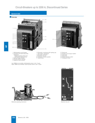
- 1. Siemens LV 30 · 20045/82 Circuit-Breakers up to 3200 A, Discontinued Series General data 5 ■Overview 1 2 3 4 5 Withdrawable circuit-breaker Indication and reset button after tripping for – tripped signaling switch and – mechanical closing lockout Spring charge indicator Contact position indicator Ready-to-close indicator 6 7 8 9 10 11 ON button, mechanical with sealing cap OFF button, mechanical ON button, electrical Electronic trip unit Indication of switch position Guide frame 12 13 14 15 16 17 Guide rails Auxiliary circuit plug-in system Crank hole Hand lever Position indicator switch Transparent cover Left: 3WN6 circuit-breaker, withdrawable version, size I, 3-pole Right: 3WN6 circuit-breaker, fixed-mounted version, size I, 3-pole Motorized operating mechanism Electronic trip unit
- 2. Siemens LV 30 · 2004 5/83 Circuit-Breakers up to 3200 A, Discontinued Series General data 5 ■Benefits Safety and reliability • High degree of protection with door sealing frame in the case of exclusively local operation of the circuit-breaker • Incoming supply from above or below, as required • Locking of the withdrawable circuit-breaker against moving, as standard • Locking of the guide frame with the circuit-breaker removed, as standard • Alarm switch for overload and short-circuit tripping with mechanical closing lockout Easy to operate • Unambiguous ON-OFF indicator with auxiliary switch for signal • Ready-to-close indicator with alarm switch as safety standard. Modular Many components, such as auxiliary releases, motorized oper- ating mechanisms, electronic trip units and current transformers can be replaced or retrofitted to adapt the circuit-breaker to changing requirements. Communication-capable (see illustration "Communication via PROFIBUS DP") The international standard PROFIBUS DP can be used to trans- mit data such as current values, switching states, reasons for tripping etc. to central computers. This makes it possible not only to monitor the circuit-breakers but also to operate them remotely. This supports energy management and significant savings in energy costs. For further information see also section "Communication-capa- ble circuit-breakers". Minimal power loss and therefore low energy consumption The low power consumption of the electrical components also saves money when it comes to purchasing the control-power transformers. Where space is at a premium or ventilation is limited. ■Area of application Specifications IEC 60947-2, DIN VDE 0660 Part 101, climate-proof to IEC 68 Part 2-30 Approval according to maritime classification see "Annex". Operating conditions The 3WN6 circuit-breakers are climate-proof in accordance with DIN IEC 68 Part 2-30. They are intended for use in enclosed areas where no severe op- erating conditions (e.g. dust, corrosive vapors, damaging gases) are present. When installed in dusty or damp areas, suitable enclosures must be provided. If damaging gases (e.g. hydrogen sulfide) are present in the surrounding air, sufficient incoming fresh air must be supplied. The permissible ambient temperatures and the associated rated currents are listed in the technical specifications. ■Design Versions Breaking capacity: 65/80 kA Rated current: 630 to 3200 A Rated operating voltage: AC 690 V The 3WN6 circuit-breakers are supplied complete with an oper- ating mechanism, electronic trip unit and auxiliary switches and are fitted with auxiliary releases. The non-automatic circuit-breakers are supplied without elec- tronic trip unit Basic configuration • Electronic trip unit for overload protection and short-circuit pro- tection, short-circuit releases also delayed for time-based dis- crimination, with LEDs for the cause of tripping, LED status in- dicator, query and test button • Mechanical closing lockout • "Tripped" switch • Ready-to-close indicator with alarm switch • Auxiliary supply connector: The circuit-breaker is equipped with the required number of connectors • Rear horizontal connection of the main conductors Operating mechanisms (see illustration "Motorized operat- ing mechanism") The circuit-breakers are available with various optional operat- ing mechanisms: • Manual operating mechanism with memory, with mechanical closing • Manual operating mechanism with mechanical and electrical closing • Motorized operating mechanism that can also be operated manually, with mechanical and electrical closing. The operating mechanisms with electrical closing can be used for synchronization tasks. Electronic trip units (see illustration "Electronic trip unit") The electronic trip unit is controlled by a microprocessor and op- erates independently of an external voltage. It enables systems to be adapted to the different protection requirements of distri- bution systems, motors, transformers and generators. When the circuit-breakers are used in IT networks that are not grounded with converters connected in parallel to a common DC link rail, suitable filter measures must be taken. Please address any questions to your regional Siemens contact. For more infor- mation on electronic trip units see "Electronic trip units" and "Functions", "Electronic trip units – General description". EMERGENCY-STOP facility The 3WN6 circuit-breakers can be used as an EMERGENCY- STOP facility to DIN VDE 0113 if the circuit-breaker is equipped with an undervoltage release and is used in conjunction with an EMERGENCY-STOP control device. Auxiliary and alarm switches • Ready-to-close If all the conditions are fulfilled, so that the circuit-breaker is ready to close, this is indicated visually on the operator panel as well as by means of an indicator switch (S7). • Contact position-independent auxiliary switches The circuit-breakers are supplied with 2 NO and 2 NC contacts or with 2 NO and 2 NC and 2 CO contacts according to order.
- 3. Siemens LV 30 · 20045/84 Circuit-Breakers up to 3200 A, Discontinued Series General data 5 Communication via PROFIBUS DP • "Tripped" switch and mechanical closing lockout As standard, the circuit-breaker is equipped with an S11 alarm switch and a mechanical closing lockout for the common over- load and short-circuit signal and, depending on the setting and version of the electronic trip unit, the ground-fault signal. The tripped signal and the standard mechanical mechanism to prevent closing remain active until the reset button is operated on the circuit-breaker. When the circuit-breaker has tripped, this is indicated by the protruding reset button. If the circuit-breaker has to be ready to close immediately after tripping, an automatic mechanical reset mechanism is avail- able, but this does not reset the electrical signal from the "tripped" switch S11. The "tripped" signal then has to be reset by operating the Reset button. The electronic trip unit offers a further option to display the cause for tripping (see trip unit, under "Functions", "Electronic trip unit – General description"). Fixed-mounted and withdrawable version Fixed-mounted and withdrawable circuit-breakers • Protective measures against arcing gases For 3WN6 circuit-breakers with voltages up to AC 415 V, screening from vertical busbars is not necessary. In the case of voltages up to AC 690 V, the arc chute cover (accessory) can be used to protect against flashover. Electrical add-on devices on the side of the circuit-breaker must be separately covered. Also see notes under "Project planning aids", "Dimension drawings". • Operator panel The operator panel is designed to protrude from a cutout in the door providing access to all operator controls and displays with the door closed. • Door sealing frame The door sealing frame seals the cabinet door with the operator panel. With the cabinet door closed, the IP degree of protection is achieved for the circuit-breaker. Withdrawable circuit-breaker The withdrawable version comprises a withdrawable circuit- breaker, a guide frame and a hand crank for moving the with- drawable circuit-breaker. The guide frames are fitted with guide rails as standard for easy handling of the withdrawable circuit- breaker. • Auxiliary supply connections The auxiliary supply connections make contact automatically when the circuit-breaker slides into the guide frame (test posi- tion, connected position). • Switch positions in the guide frame The withdrawable version has three switch positions in the switchgear cabinet behind the cabinet door: - Connected position (main circuit and auxiliary circuit ready) - Test position (main circuit disconnected, auxiliary circuit ready) - Disconnected position (main circuit and auxiliary circuit disconnected) In the disconnected position, the withdrawable circuit-breaker complies with the "isolation condition" with a visible isolating dis- tance in the main circuit and auxiliary circuit. The circuit-breaker must always be switched off before it is moved. The "OFF" button must be held down when the slide in the crank hole is opened. S 7 - 3 0 0 M 3 M 3 M 3 N S E 0 _ 0 1 1 2 5 M 3 B E R O p r o x i m i t y s w i t c h S I G N U M a c t u a t o r s M o d u l e s i n I P 6 7 C o m p a c t s t a r t e r i n I P 6 5 S i g n a l l i n g c o l u m n D P / A S - I n t e r f a c e g a t e w a y M A S T E R D R I V E E T 2 0 0 X d i s t r i b u t e d I / O d e v i c e 3 U F S S I M O C O D E - D P m o t o r p r o t e c t i o n a n d c o n t r o l d e v i c e D P / 3 W N 6 i n t e r f a c e a n d 3 W N 6 c i r c u i t - b r e a k e r S I M A T I C H M I v i s u a l i z a t i o nS I M A T I C S 5 / S 7 A
- 4. Siemens LV 30 · 2004 5/85 Circuit-Breakers up to 3200 A, Discontinued Series General data 5 Guide frames Closing of the crank hole is only possible in the circuit-breaker positions (connected, test or disconnected position). The circuit- breaker position is shown on a display on the circuit-breaker. The circuit-breaker is moved with the help of a hand crank. The connected position as well as the disconnected position is achieved by moving the circuit-breaker to the end stop. • Position indicator switches The position indicator switches are operated by the withdraw- able circuit-breaker via an additional mechanical device. Apart from indicating the position, they also indicate that the circuit- breaker is present in the guide frame. This version is suitable for interlock circuits including other protective devices. • Shutters Inadvertent touching of live main contacts or busbars is pre- vented by covering with a shutter. The shutter is constructed in two parts and allows the upper or lower connection areas to be opened separately for the purpose of checking that they are not live. The divided shutter can be interlocked in the open or closed position and two padlocks can be fitted. • Coding unit To prevent circuit-breakers of the same size but of different de- signs being mixed up in a switchgear cabinet, the withdraw- able circuit-breakers and guide frames can be equipped with a coding device. The coding device provides coding protec- tion for up to 35 circuit-breakers. The circuit-breakers in the withdrawable version are factory- fitted with a rated current coding as standard. This prevents a withdrawable circuit-breaker being used in a guide frame that has a different rated current. • Blocking mechanisms Fixed-mounted circuit-breakers: To protect the operating personnel and the switchgear, the fixed-mounted circuit-breakers can be fitted with a locking mechanism that prevents the switchgear cabinet door being opened when the circuit-breaker is closed. Withdrawable version: For the protection of the operating personnel and the switch- gear, the withdrawable versions can be equipped with the following locking devices: - Blocking device to prevent opening of the cabinet door, ac- tive in the connected position. - Blocking device to prevent closing with the cabinet door open, active in the connected position. - Blocking mechanism against movement with the cabinet door open If the cabinet door is opened, the manual crank used to move the circuit-breaker cannot be positioned. • Blocking mechanism against insertion of the withdrawable circuit-breaker The guide rails can be interlocked with one slide each and locked with two padlocks. • Blocking mechanism against moving the withdrawable circuit- breaker A padlock prevents access to the crank hole and application of the crank (max. shackle diameter: 8 mm; possible with all versions) or the same can be achieved with an additionally available safety lock (see "Functions", "Opening, closing and locking devices"). Main circuit connections Guide frame Locking device to prevent insertion of the withdrawable circuit-breaker Main circuit termi- nals rear, horizontal (standard) Main circuit termi- nals accessible from front, single hole at top and bottom Main circuit terminals accessible from front, double hole at top and bottom, holes in accordance with DIN 43673 Rear, horizontal connections with guide rails (standard) Rear vertical terminal at top and bottom Terminal accessible from front at top and bottom, holes in accordance with DIN 43673, double hole. Single hole: shorter bar Fixed-mounted circuit-breakers Withdrawable circuit-breakers Guide rail Position indicating switch Shutter
- 5. Siemens LV 30 · 20045/86 Circuit-Breakers up to 3200 A, Discontinued Series General data 5 Electronic trip units Electronic trip unit version B "azn" Electronic trip unit version J/K "aznNg" Electronic trip unit version E/F "aznNg" Electronic trip unit version P "aznNg"; Electronic trip unit version N "aznN" without ground-fault release
- 6. Siemens LV 30 · 2004 5/87 Circuit-Breakers up to 3200 A, Discontinued Series General data 5 ■Functions Electronic trip units - General description The new generation of solid-state microprocessor-based elec- tronic trip units Overload protection ("a") Inverse-time delayed overload release for overload protection of load feeders and cables. Selective short-circuit delayed short-circuit protection ("z") Instantaneous short-circuit protection ("n") Ground-fault protection ("g") For sensing of fault currents that flow to ground and that can cause fire in the plant. Electronic trip units - versions B and N In all electronic trip units, the following functions are included as standard: • Integrated function test The test button can be used to test the electronic trip unit using an integrated test function with or without tripping of the circuit-breaker (the solid-state trip unit, trip solenoid and breaker mechanism are tested). • Active LED Correct operation of the electronic trip unit is indicated by the "heartbeat" of a green flashing LED. When the operating current exceeds the response threshold of the overload protection, this is indicated by rapid flashing. • Cause of tripping The cause of tripping can be queried locally and displayed (by pressing the "Query" button). • μP faults A microprocessor fault is signaled by a warning indicator (also optionally via an optocoupler as well). • Overtemperature If the temperature in the electronic trip unit exceeds 85 °C, this is indicated by an LED (also optionally via an optocoupler). Indication on electronic trip unit version N N S E 0 _ 0 1 1 2 6 N S E 0 _ 0 1 1 2 7 N S E 0 _ 0 1 1 2 8 N S E 0 _ 0 1 1 2 9
- 7. Siemens LV 30 · 20045/88 Circuit-Breakers up to 3200 A, Discontinued Series General data 5 Comprehensive additional functions – in accordance with the design of the electronic trip unit, e.g.: • Short time-delay short-circuit release with I2t-dependent delay for improved discrimination to the downstream fuses • Short-circuit protection with "Zone Selective Interlocking" for significant reduction of the stress and damage in a distribution system thanks to short delay times. • Load shedding/load receiving • Communication via PROFIBUS DP • LCD operating current display Ground-fault protection • Description Ground-fault releases "g" sense fault currents that flow to ground and that can cause fire in the plant. Multiple circuit- breakers connected in series can have their delay times ad- justed so as to provide graduated discrimination. When setting the parameters for the electronic trip unit it is pos- sible to choose between "Alarm on detection" and "Trip circuit- breaker on detection". The reason for tripping is indicated by means of an LED when the query button is activated. • Measurement methods - Vectorial summation formation with current transformer in neutral conductor The neutral conductor current is measured directly and is evaluated for neutral conductor overload protection. The electronic trip unit determines the ground-fault current by means of vectorial summation current formation for the three phase currents and the N-conductor current. Three-pole circuit-breakers, current transformers in the neutral conductor For 4-pole circuit-breakers, the fourth current transformer for the N-conductor is installed internally, for the electronic trip unit version E and J it must be mounted externally to the in- coming or outgoing feeder side. - Direct acquisition of the ground-fault current by means of a current transformer in the grounded neutral point of the trans- former. The current transformer is installed directly into the grounded neutral point of the transformer. Three-pole circuit-breakers, current transformers in the grounded neutral point of the transformer. Four-pole circuit-breakers, current transformers in the grounded neutral point of the transformer (connection as for three-pole circuit-breakers) Additional functions 1 • External DC 24 V supply e.g. for parameterization (i.e. setting the protection parameters and additional functions), activation of operating current indi- cation (version D, E/F, H, J/K, N/P) if no load current is flowing in the main circuits. • μP-fault The alarm LED is activated for all versions if the microproces- sor is faulty. For the additional functions 1 and 2, a signal can also be issued via the optical coupler. The circuit-breaker is not tripped in this case. However, the protection function is se- cured by means of a redundant bypass. • Temperature alarm If the temperature in the electronic trip unit exceeds the limit value of 85 °C, this is indicated by means of an LED. For the additional functions 1 and 2, a signal can also be issued via the optical coupler. Additional functions 2 • External DC 24 V power supply (see additional functions 1) • μP fault (see additional functions 1) • Temperature alarm (see additional functions 1) • Leading signal "a" trip The leading signal (via optical coupler) for the overload trip is used to deactivate the downstream thyristor control devices. The overload tripping operation is then performed after 200 ms. Electronic trip unit version Current transformer T5 must be con- nected to auxiliary current connec- tion • C, D, E, H, J • N, P 400.13 400.14 300.1 300.2 Electronic trip unit version Current transformer T5 must be connected to auxiliary current connection • E, J 400.13 400.14 N S E 0 _ 0 1 1 3 0 L 1 L 2 L 3 N T 5 3 W N 6 N S E 0 _ 0 1 1 3 1 P E Electronic trip unit version Current transformer T6 must be con- nected to auxiliary current connec- tion • C, E, J, P 400.13 400.14 N S E 0 _ 0 1 1 3 2 L 1 L 2 L 3 N P E T 6 3 W N 6 N S E 0 _ 0 1 1 3 3 L 1 L 2 L 3 N P E T 6 3 W N 6
- 8. Siemens LV 30 · 2004 5/89 Circuit-Breakers up to 3200 A, Discontinued Series General data 5 • Load monitoring Load monitoring is adjustable via two selectable operating val- ues for load receiving and load shedding (IAW1, IAW2) and a common delay time (td, AW). • "g" alarm Signal via optical coupler on ground fault • Zone Selective Interlocking (see short-circuit protection with Zone Selective Interlocking "ZSI"). Hand-held device • Description The hand-held device is connected to the electronic trip unit by means of a connecting lead and a snap-on power supply adapter. A DC 24 V power supply can be connected to the adapter to activate the trip unit. This hand-held device can also be used for the communication-capable motor protection and control device 3UF5 (SIMOCODE-DP) for configuration and operation. • Functions Reading and writing the protection parameters for electronic trip unit versions H, J/K, N, and P. Connecting and setting operating values for the additional functions of the electronic trip unit versions D, E/F, H, J/K, N, and P. The settings read out from the trip unit can be temporarily stored in the hand-held device and written to a different elec- tronic trip unit. Hand-held device Short-circuit protection with Zone Selective Interlocking The Zone Selective Interlocking function permits full discrimina- tion for the very short delay time of tzsi = 50 ms regardless of the number of staggered levels and location of the short-circuit in the distribution system. Reduction of the break time reduces the stress and damage that can occur in a distribution system considerably. If the Zone Selective Interlocking function is set and a short-cir- cuit occurs, every circuit-breaker through which the short-circuit flows interrogates the next circuit-breaker immediately down- stream for presence of the short-circuit current in the next lower staggered level. M NSE0_01134 Q 2 1 Q 3 1 Q 3 2 Q 1 1 Q 2 2 Q 3 3 Q 4 1 K 1 K 2 K 3
- 9. Siemens LV 30 · 20045/90 Circuit-Breakers up to 3200 A, Discontinued Series General data 5 Functional overview of the electronic trip unit system All specified delay times are minimum non-release times (circuit-breaker opening time approx. 20 ms). 1) With 3-pole circuit-breakers a current transformer is required in addition if there is asymmetrical loading of the phases. In the case of 4-pole circuit- breakers a current transformer in the neutral conductor is fitted internally in the circuit-breaker (exception: electronic trip units E and J). For current transformers to be ordered separately see Page 5/108. Function Basic functions Overload protection Inverse-time delayed overload release "a" for the phases Adjustment of the current setting Ir from 40 % to 100 % In Graduation 5 % Graduation freely programmable Time-lag class Tc = opening time at 6 × Ir, setting Tc Thermal image "Phase-failure sensitivity" (reversible) for the neutral conductor1) Adjustment of the current setting In Time-lag class Tc of the neutral conductor as for the phases Short-circuit protection Short-time delayed short-circuit release "z" Setting the operating current Id Setting the delay time td With I2td-dependent delay, delay time td Instantaneous short-circuit release "n" Setting the operating current Ii Ground-fault protection Ground-fault release "g"1 ) Setting the operating current Ig Setting the delay time tg With I2 tg-dependent delay, delay time tg LCD display Operating current indication LED display Status indication Flashing LED when electronic trip unit activated "Tripped" indication "a" release "z/n" release "z" release "n" release "N" release N "g" release/alarm Alarm indication μP fault θ, temperature > 85 °C phase unbalance freely assignable indication Test Internal self-test and display via LED Connection of the test device to test connector X3 Basic configuration Signal by signaling switch (1 NO) Ready-to-close Circuit-breaker can be safely closed "Tripped" switch Latching; active after "a", "z", "n", "g"2 ) release with/without mechanical closing lockout Additional function Signal via optocoupler outputs Additional functions 1 External DC 24 V supply (e.g. for parameterization), current input 250 mA μP fault θ, temperature > 85 °C linked with phase unbalance Additional functions 2 External DC 24 V supply (e.g. for parameterization), current input 250 mA μP fault θ, temperature > 85 °C linked with phase unbalance Leading signal "a" release (200 ms to release)/load shedding Load monitoring; operating value 50 to 150 %, 1 to 15 s "g" alarm Zone Selective Interlocking between 3WN and 3WS Communication via PROFIBUS DP Data transmission Communication module in conjunction with additional functions 2 and interface DP/3WN6 Data transmission and measured-value acquisition Measurement module in conjunction with additional functions 2 and interface DP/3WN6 a N S E 0 _ 0 1 1 3 6 c N S E 0 _ 0 1 1 3 5 z N S E 0 0 1 1 3 7 n N S E 0 0 1 1 3 8 g O p t
- 10. Siemens LV 30 · 2004 5/91 Circuit-Breakers up to 3200 A, Discontinued Series General data 5 Electronic trip unit version (r 10th pos. of Order No.) V "zn" B "azn" C/G "aznNg" D "aznN" E/F "aznNg" H "aznN" 7 J/K "aznNg" 7 N "aznN" P "aznNg" 4 4 4 4 4 4 4 4 10 s3) 10 s3) 2–30 s 2–30 s 2–30 s 2–30 s 2–30 s 2–30 s 4 4 4 4q 4 4 ✕ x x x 4 4 4 4 50 or 100 % 50 or 100 % 50 or 100 % 20–100 % 20–100 % 20–100 % 20–100 % 1.25–12×Ir Ir=40–100 % In 1.5–12×Ir 1.25–12×Ir 1.25–12×Ir 1.25–12×Ir 0.5–12×In 0.5–12×In 1.25 × Ir – 40 kA 1.25 × Ir – 40 kA 0; 20–500 ms 0; 20–400 ms 0; 20–400 ms 20–400 ms 20–400 ms 20–4000 ms4 ) 20–4000 ms4 ) 20–400 ms 20–400 ms 80–300 ms 80–300 ms 80–300 ms 80–300 ms 80–300 ms 80–300 ms >15×In >15×In >15×In >1.5–12×In and Ii=∞ with setting Ii=∞ then Icu=Ics=Icw (lowest value decisive) >1.5–12×In with Ii=∞ with setting Ii=∞ then Icu=Ics=Icw (lowest value decisive) >1.5–12×In with Ii=∞ with setting Ii=∞ then Icu=Ics=Icw (lowest value decisive) >1.5–12×In with Ii=∞ with setting Ii=∞ then Icu=Ics=Icw (lowest value decisive) Size I: up to 50 kA Size II: up to 65 kA Size I: up to 50 kA Size II: up to 65 kA 0.2–0.6×In 0.2–0.6×In 20 % In up to 1200 A 20 % In up to 1200 A 100–500 ms 100–500 ms 100–500 ms 100–500 ms 100–500 ms 100–500 ms 100–500 ms 4 4 4 4 4 4 4 4 4 4 4 4 4 4 4 4 4 4 4 4 4 4 4 4 4 4 4 4 4 4 4 4 4 4 4 4 4 4 4 4 4 4 4 4 4 4 4 4 4 4 4 4 4 4 4 4 4 4 4 4 4 7 4 7 4 7 4 7 4 4 4 4 4 4 4 4 4 4 4 4 4 4 4 4 4 4 4 4 4 4 4 4 4 4 4 4 4 4 4 4 4 4 4 4 4 4 x x x x 4 4 x x x x x x x x 7 x x 7 x x 7 x x 7 x x x x x x x x 4 4 x x x x x x x x 7 ✕ x 7 ✕ x 7 ✕ x 7 ✕ ✕ x x x 7 ✕ 7 x 7 x 7 x x x 7 x 7 x 7 x 7 x x x x x x x x x x x x x x x x x x x 2) "g" release occurs with "Trip" setting on the electronic trip unit. 3) Where there is heavy starting of motors, the time setting Tc = 10 s may not be sufficient: use version D, E/F, H, J/K or P. 4) For td > 500 ms: Icu = Icw = Ics (lowest value decisive) and Id automatically limited to 15 kA. 4 Function available as standard x Function optional (additional cost) 7 Deselect/set function with hand-held device Function active when td is set to 20 ms ✕ Available with electronic trip unit B only from date of manufacture 02.96
- 11. Siemens LV 30 · 20045/92 Circuit-Breakers up to 3200 A, Discontinued Series General data 5 Communication module (Z = F01) • The electronic trip units are internally equipped with an addi- tional communication module for communication via PROFIBUS DP (in this case please use the prefix Z with the Order Number i.e. Z=F01). The data are transferred over a 3 m plug-in connection (included in scope of supply) to an external DP/3WN6 interface. This converts the data for PROFIBUS DP. The following useful data are available depending on the ver- sion and accessories of the circuit-breaker: - Analog measured values: Phase currents IL1, IL2, IL3, Imax and Imin, N-conductor current IN Ground-fault current Ig - Event signals: Type of previous tripping operation (a, z, n, g, N), μP fault, temperature alarm, phase symmetry, load shedding, load receiving, overload - Operating states: Switch on/off, ready indication, status of the voltage/undercurrent release, storage spring loaded, position (test and connected position) of the withdrawable circuit-breaker, test of the electronic trip unit - Remote configuration - Read out configuration data: Settings for the protection functions - Rated current for the circuit-breaker, number of poles, identification code for circuit-breaker - Diagnostics data: Average current for previous fifteen minutes - Remote control: To open and close the circuit-breaker provided that it is equipped with electrical querying and a shunt release. • Remote configuration The additional functions and protection functions can be set via the bus. The electronic trip unit checks whether the values for the protection parameters are valid and within range. Measurement module (Z = F05) The electronic trip unit versions N and P can be also be equipped with a measurement module (please quote the follow- ing Order No. when ordering: Z=F05 instead of Z=F01). The measurement module consists of the communication module with additional measurement functions and external voltage transformers. In this way, the voltage and frequency are ac- quired in addition to the current values, which makes the follow- ing additional operating values available: • Voltage UactL, UmaxL, UminL (15-minute value for max. and min.) ULL1, ULL2, ULL3 (conductor/conductor voltage) • Frequency fact, fmax, fmin (15-minute value for max. and min.) • Power factor • Active power P • Reactive power Q • Apparent power S • Active work W • Direction of phase rotation. These values can be used for energy management by switching loads on/off to avoid expensive load peaks. The following signal and protection functions for tripping are available: • Asymmetrical phase for voltage and current • Undercurrent/overcurrent • Underfrequency/overfrequency • Reversed flow of energy The data can also be displayed locally by the electronic trip unit. The voltage transformers for the measurement module must be mounted externally. They are mounted on a 35 mm mounting rail. The voltage transformers are included in the scope of supply of the measurement module. The measurement module cannot be retrofitted. Opening, closing and locking devices • ON and OFF buttons - Mechanical ON button In the standard version, the mechanical ON button is a push- button. In operating mechanisms with electrical closing, the mechanical ON button is fitted with a sealing cap. As an al- ternative to a pushbutton, a safety lock (CES, BKS, IKON) can also be supplied. If the key is removed in the "0" position, it is no longer possible to close the circuit-breaker mechanically. - "Electrical ON" button The "electrical ON" button is intended for normal activation during service. External electrical interlocks can be imple- mented easily using the "electrical ON" button. A sealing cap is available for the "electrical ON" button. - Mechanical OFF button In the standard version, the mechanical OFF button is a push- button. An additional sealing cap secures the button against unauthorized operation. As an alternative to the OFF button, the following are avail- able: - Safety lock The key can be removed in the OFF position to ensure that the circuit-breaker cannot be closed mechanically. The same key can then be used to unlock another circuit-breaker. - EMERGENCY-STOP button This mushroom button latches in the OFF position when it is pressed and prevents the circuit-breaker closing until the latching is reset by rotating the mushroom button. - Locking device against closing A flap of the locking device covers the "electrical ON" button and continuously depresses the "mechanical OFF" button. The locking device can be secured with up to 4 padlocks.
- 12. Siemens LV 30 · 2004 5/93 Circuit-Breakers up to 3200 A, Discontinued Series General data 5 - CASTELL, FORTRESS or KIRK-KEY lock These locking devices are supplied with a mounting set. The lock must be ordered from the manufacturer of the locks. When the lock is activated, the circuit-breaker is locked against closing. The disconnection condition is fulfilled in the OFF position. An additional access block with a flap for CASTELL, FORTRESS and KIRK-KEY locks prevents insertion of the key. This device can be locked with up to four padlocks. • Locking device against moving the withdrawable circuit- breaker Access to the crank hole and application of the crank is pre- vented by means of one or more padlocks. An additional safety lock which can be supplied on request also prevents access to the crank hole in position I (key can be removed). This also pre- vents movement of the withdrawable circuit-breaker in the guide frame. • Locking device in the cabinet door A safety lock which is fixed to the cabinet door prevents the circuit-breaker from closing. Interlocking is only effective in the connected position in the case of withdrawable circuit-break- ers. The signal is transmitted via a Bowden wire. For locking mechanisms please refer to "Installation", "Guide frames". • Transparent cover over electronic trip unit The standard transparent cover can be sealed. The configura- tion sections are covered to prevent unauthorized access. Openings allow access to the query and test button. A hinged flap covers the whole operator panel of the electronic trip unit. • Motor switch An additional motor switch can deactivate automatic loading of the storage spring on closing. This means that the control sup- ply does not need to be switched off for maintenance mea- sures to the circuit-breaker. • Operating cycles counter A five-digit operating cycles counter is available for the 3WN6 circuit-breakers. The display is incremented by "1" as soon as the storage spring is fully loaded. • Auxiliary release Up to two auxiliary releases can be installed at the same time. The following are available: 1 shunt release or 1 undervoltage release or 2 shunt releases or 1 shunt release + 1 undervoltage release The shunt release "f" has been designed for permanent excita- tion. This means that it is also possible to block the circuit- breaker against being jogged into closing. An energy storage device for shunt releases allows the circuit- breaker to be opened even if the control voltage is no longer available. The undervoltage release "r" is available without delay as stan- dard (jumper-selectable to 100 ms by customer). In addition, the undervoltage release "rc" with a delay in the range from 0.2 to 3.2 s is available. For further information on the selection, ordering and project engineering of communication-capable circuit-breakers, refer to section 3 "Communication-capable circuit-breakers" and the manual "Communication links for 3VF, 3WN6, 3WN1/3WS1 circuit-breakers to PROFIBUS DP" Order No. E20001-P285-A644-V1. Opening, closing and locking devices Undervoltage release "rc" with delay for mounting in 3WN6 circuit-breaker 1 Operating cycles counter 2 Transparent cover over electronic trip unit 3 Motor switch 4 Sealing cap for mechanical ON button 5 EMERGENCY-STOP button instead of the OFF button 6 Safety lock to prevent opening of the crank hole 7 Padlock to prevent opening of the crank hole 8 Safety lock instead of the mechanical ON button 9 Locking device for mechanical OFF button and electrical ON button 10 Installation location for CASTELL, FORTRESS, or KIRK-KEY lock
- 13. Siemens LV 30 · 20045/94 Circuit-Breakers up to 3200 A, Discontinued Series General data 5 Module for mutual mechanical interlocking The module for mutual mechanical interlocking can be used for one or two 3WN6 circuit-breakers and can be adapted easily to the corresponding versions. The fixed-mounted and withdrawable circuit-breaker versions are fully compatible and can therefore be used in a mixed con- figuration in an installation. The circuit-breakers can be mounted alongside each other or one above the other, whereby the spacing of the circuit-breakers is determined solely by the length of the Bowden cable. The Bowden cables are supplied in standard lengths of 2 m. Inter- lock signals are looped through via the Bowden cables. Inter- locking is only effective in the connected position in the case of withdrawable circuit-breakers. The mechanical lifetime of the Bowden cables is 10,000 operat- ing cycles. The interlocking module is mounted on the right-hand side of the fixed-mounted circuit-breaker (see illustration) or the guide frame. 3WN6 circuit-breaker, 4-pole, with interlocking module and Bowden wire Interlocking module with Bowden wire Example Version Switch status Description 1 A B 2 circuit-breakers alongside each other: 0 1 0 0 0 1 One circuit-breaker can only be closed when the other has been switched off. Each circuit-breaker has an interlocking module and a Bowden wire. 2 A B C 3 circuit-breakers one above the other: 0 1 0 0 1 0 1 0 0 1 0 1 1 0 0 0 0 1 0 1 1 Any two circuit-breakers can always be closed, with the third one being interlocked. Each circuit-breaker has an interlocking module and a Bowden wire. An additional Bowden wire must be ordered separately for each circuit-breaker. 3 A B C 3 circuit-breakers one above the other: 0 1 0 0 0 0 1 0 0 0 0 1 When one circuit-breaker is closed the other two circuit-breakers cannot be closed. The interlocking mechanism of each circuit-breaker consists of an interlocking module and a Bowden wire. An additional Bowden wire must be ordered separately for each circuit-breaker. 4 A1 B A2 3 circuit-breakers alongside each other: 0 1 0 1 0 0 0 0 0 1 0 0 1 1 0 Two circuit-breakers can be closed and opened independently of each other, while the third is only ready to close when the two others are open. If the third circuit-breaker is closed, the other two circuit-breakers cannot be closed. All three circuit-breakers each have an interlocking module and a Bowden wire. A Bowden wire must be ordered separately. G BA NSE0_01139 CA B NSE0_01140 A CB NSE0_01141 A 2A 1 G B NSE0_01142
- 14. Siemens LV 30 · 2004 5/95 Circuit-Breakers up to 3200 A, Discontinued Series General data 5 Transfer control device The transfer control device allows automatic network switcho- vers from a standard-network supply to an emergency-network supply. Standard and emergency-network supply: AC 380/400 V A transformer is generally used for standard-network supplies. The emergency-network supply is usually provided by a gener- ator or transformer. The transfer control device monitors the infeed side of both cir- cuit-breakers. If the standard-network supply fails, the emer- gency network is switched on automatically. When the standard- network returns, it is also reactivated automatically. The switchover requires two circuit-breakers with the basic configuration 3WN6 _ _ _- _ _ _ 58 - 1KA _ (the blank spaces can be configured as required) and one trans- fer control device 3WX36 66-7JA00. The transfer control device can be mounted to the wall or installed in the control cabinet. It can be installed in the control cabinet without an enclosure. The transfer control device can be used to implement automatic network switchovers to IEC 60947-6-1. The two 3WN6 circuit-breakers must be mutually interlocked for this purpose. (See "Accessories/spare parts", "For fixed- mounted and withdrawable circuit-breakers", "Mutual mechani- cal interlocking".) Transfer control device Mode of operation of the transfer control device N S E 0 _ 0 1 1 4 3 G 3 W N 6 3 W N 6 A N e t w o r k - s w i t c h i n g c o n t r o l u n i t N S E 0 _ 0 1 1 4 4 0 A U T 0 0 A U T 0 A U T 0 A U T A M a i n o r b a c k - u p n e t w o r k a v a i l a b l e M a i n n e t w o r k M a i n n e t w o r k a v a i l a b l e Q N : O N Q G : O F F A U T O M A T I C M a i n n e t w o r k a v a i l a b l e D e l a y ³ T 1 ? ( 1 , 5 t o 3 0 s ) Q N : O N Q G : O F F Q N : O F F Q G : O F F M a i n n e t w o r k f a i l s a n d b a c k - u p n e t w o r k i s a v a i l a b l e Q N : O N Q G : O F F R e t u r n t o m a i n n e t w o r k Q N : O N Q G : O F F M a i n n e t w o r k f a i l s a n d b a c k - u p n e t w o r k i s a v a i l a b l e Q N : O N Q G : O F F B a c k - u p n e t w o r k B a c k - u p n e t w o r k a v a i l a b l e R e t u r n t o m a i n n e t w o r k Q N : O F F Q G : O N Q N : O F F Q G : O N B a c k - u p n e t w o r k f a i l s Q N : O F F Q G : O N D e l a y ³ T 1 ? ( 2 t o 1 0 0 s ) R e t u r n t o m a i n n e t w o r k Y e s N o N o Y e s Q N : O F F Q G : O N
- 15. Siemens LV 30 · 20045/96 Circuit-Breakers up to 3200 A, Discontinued Series General data 5 ■Technical specifications 1) Figures apply to circuit-breakers with order code "K03", see "Options". 2) For fixed-mounted circuit-breakers with horizontal connection, for with- drawable circuit-breakers with vert. conn., see manual for 3WN6 circuit- breakers. 3) The temperatures apply to the air surrounding the upper third of the circuit- breaker. 4) These values apply in the case of sinusoidal current (50/60 Hz). The heat- ing/losses increase in the event of harmonics and higher frequencies. 5) Maintenance: replacement of the contact set. 6) Per contact set. Disconnect. of the rated current In and power factor = 0.8. 7) Rated insulation voltage Ui = AC 1000 V. Size I II Type 3WN6 0 3WN6 2 3WN6 4 3WN6 5 3WN6 6 3WN6 7 Rated current In at 55 °C, at 50/60 Hz Main conductor A 630 1000 1600 2000 2500 3200 Neutral conductor (only on 4-pole vers.) A 630 1000 1600 2000 2500 3200 Rated operating voltage Ue at 50/60 Hz AC V up to 690 Rated impulse withstand voltage Uimp Main circuits7 ) Auxiliary circuits kV kV 8 4 Utilization category B Rated short-circuit making capacity Icm (peak value) up to AC 415 V up to AC 500 V up to AC 690 V kA kA kA 143 143 110 176 176 110 Rated service short-circuit breaking capacity Ics (rms value) up to AC 415 V up to AC 500 V up to AC 690 V kA kA kA 65 65 50 80 80 50 Rated ultimate short-circuit breaking capacity Icu (rms value) up to AC 415 V up to AC 500 V up to AC 690 V kA kA kA 65 65 50 80 80 50 Permissible ambient temperatures Operation Storage °C °C –20 ... +70 –40 ... +80 Rated short-time withstand current Icw at 50/60 Hz 0.5 s 1 s 2 s 3 s 4 s kA kA kA kA kA 50 35/501 ) 25/301 ) 20/251 ) 17/201 ) 50 50 30 25 20 65 65 60 50 40 Permissible load for fixed-mounted and withdrawable circuit- breakers at cabinet interior temperature 2 )3 )4 ) up to 55 °C at 60 °C at 70 °C A A A 630 630 630 1000 1000 1000 1600 1600 1530 2000 2000 2000 2500 2350 2330 3200 2860 2650 Rated rotor operating voltage Uer V 2000 Power loss at In with 3-phase symmetr. load (without line-side busbars and metal components2 )4 ) Fixed-mounted cir.-br. W 40 90 140 170 260 420 Withdrawable circuit- breaker including guide frame W 80 205 310 310 510 760 Service life with maintenance5 ) without maintenance5 ) mechanical electrical mechanical electrical6 ) Op. cycles Op. cycles 20000 20000 10000 6000 20000 20000 10000 2000 Operating frequency 1/min 1 Minimum interval between tripping operation by electronic trip unit and next making operation of the circuit-breaker (only with automatic mechanical resetting of the lockout device) ms 80 Service position Degree of protection Circuit-breaker IP20, when fitted in cabinet or frame Operator panel with door sealing frame IP54 Main conductor minimum cross-sections Copper bars, bare Qty. mm2 1 × 50 × 10 2 × 40 × 10 2 × 60 × 10 2 × 100 × 10 3 × 100 × 10 3 × 100 × 10 Copper bars, painted black Qty. mm2 1 × 40 × 10 1 × 60 × 10 2 × 50 × 10 2 × 80 × 10 2 × 100 × 10 3 × 100 × 10 Auxiliary conductors (Cu) Max. no. of aux. conduc- tors × cross- section solid and finely stranded with end sleeves 1 × 0.5 ... 2.5 mm2 ; 1 × AWG 14 2 ×1.0 mm2 Weights 3-pole circuit- breakers Fixed-mounted circuit-breaker approx. kg 34 34 36 57 59 61 Withdrawable circuit-breaker approx. kg 36 36 38 59 61 63 Guide frame approx. kg 22 22 23 35 37 37 4-pole circuit- breakers Fixed-mounted circuit-breaker approx. kg 47 47 49 70 72 74 Withdrawable circuit-breaker approx. kg 49 49 51 72 74 76 Guide frame approx. kg 27 27 28 46 48 48 and/ or N S E 0 _ 0 0 0 6 1 3 0 ° 3 0 ° N S E 0 _ 0 0 0 6 2 3 0 ° 3 0 °
- 16. Siemens LV 30 · 2004 5/97 Circuit-Breakers up to 3200 A, Discontinued Series General data 5 1) The operating range is only permissible for the specified rated voltages and corresponds to the battery charging voltage. 2) Storage time = maximum time after which tripping by the shunt release is still assured after loss of the auxiliary voltage supply. The precondition for this is that the stored energy feature was fully charged. 3) Recharging time = minimum time for recharging the stored energy feature after tripping by the shunt release. Operating mechanisms Manual operating mechanism with memory, with mechanical closing Closing Charging stored- energy feature Max. force required to operate the hand lever Required number of strokes on the hand lever N 210 5 Manual operating mechanism with mechanical and electrical closing Charging stored- energy feature Closing solenoid (Y1) see "Manual operating mechanism with stored-energy feature with mechanical closing" Operating range 0.7 ... 1.1 × Us Extended operating range for battery operation1 ) for DC 24 V, DC 48 V, DC 60 V, DC 110 V, DC 220 V 0.7 ... 1.26 × Us Power input AC/DC VA/W 15 Minimum command duration at Us for the activation solenoid ms 60 Total closing time at Us after start of closing command for the activation solenoid, suitable for synchronizing tasks ms 80 Short-circuit protection Smallest permissible DIAZED fuse (operational class gL)/miniature circuit-breaker with C-characteristic 1 A TDz (time-lag)/1 A Manual/motor operating mechanism with mechanical and electrical closing Manual operating mechanism see "Manual operating mechanism with stored-energy feature with mechanical closing" Motor Operating range 0.7 ... 1.1 × Us Extended operating range for battery operation1) for DC 24 V, DC 48 V, DC 60 V, DC 110 V, DC 220 V 0.7 ... 1.26 × Us Power input to motor AC/DC VA/W 40 Time required to charge the stored-energy mechanism 1 × Us s 20 Closing solenoid see "Manual operating mechanism with stored-energy feature with mechanical and electrical closing" Short-circuit protection Motor and activation solenoid for the same rated control supply voltages: For motor and closing solenoid Smallest permissible DIAZED fuse (operational class gL)/miniature circuit-breaker with C-characteristic at Us = 24 V 2 A TDz (time-lag)/2 A at Us = 110–127 V 1 A TDz (time-lag)/1 A at Us = 220–250 V 1 A TDz (time-lag)/1 A Auxiliary releases Shunt release "f" (F1, F2) Operating value pickup ≥ 0.7 × Us (circuit-breaker is tripped) Operating range 0.7 ... 1.1 × Us For continuous command (100 % duty ratio), locks out on momentary-contact commands Extended operating range for battery operation1 ) for DC 24 V, DC 30 V, DC 48 V, DC 60 V, DC 110 V, DC 220 V 0.7 ... 1.26 × Us Rated control supply voltage Us AC 50/60 Hz DC V V 110–127, 220–240 24,48, 60, 110–125, 220–250 Power input AC/DC VA/W 15 Minimum command duration at Us ms 60 Opening time of circuit-breaker at Us = 100 % AC/DC ms ≤ 80 Short-circuit protection Smallest permissible DIAZED fuse (operational class gL)/miniature circuit-breaker with C-characteristic 1 A TDz (time-lag)/1 A With stored energy feature consist- ing of f release and 3WX31 56-1J.01 storage device Rated control supply voltage Us AC 50/60 Hz DC V V 110–127, 220–240 110–125, 220–250 Operating range 0.85 ... 1.1 × Us Power input AC/DC VA/W 1 Storage time2 ) at Us/recharging time3 ) at Us max. 5 min/min. 5 s Opening time of circuit-breaker, short-circuit protection as with "for continuous command"
- 17. Siemens LV 30 · 20045/98 Circuit-Breakers up to 3200 A, Discontinued Series General data 5 1) The operating range is only permissible for the specified rated voltages and corresponds to the battery charging voltage. 2) Without any welding of the contacts only at Ik ≤ 1 kA in accordance with DIN VDE 0660 Part 200. Auxiliary releases Undervoltage release "r" (F3) and "rc" (F8) Operating values pickup dropout ≥ 0.85 × Us (circuit-breaker can be closed) (0.35 ... 0.7) × Us (circuit-breaker is tripped) Operating range 0.85 ... 1.1 × Us Extended operating range in battery operation1 ) for DC 24 V, DC 30 V, DC 48 V, DC 60 V, DC 110 V, DC 220 V 0.7 ... 1.26 × Us Rated control supply voltage Us AC 50/60 Hz DC V V 110–127, 220–240, 380–415 24, 48, 60, 110–125, 220–250 Power input AC DC VA W 15 15 Opening time of circuit-breaker at Us = 0 Design "r" (F3) Instantaneous With 100 ms delay ms ms ≤ 100 ≤ 300 Design "rc" (F8) With delay, td = 0.2 ... 3.2 s s 0.2 ... 3.2 Reset via additional NC contact – direct switching-off ms ≤ 100 Short-circuit protection Smallest permissible DIAZED fuse (operational class gL) /miniature circuit-breaker with C-characteristic 1 A TDz (time-lag)1 A Contact position-driven auxiliary switches (S1, S2, S3, S4) Rated insulation voltage Ui AC/DC V 400 V Rated operating voltage Ue 400 V Switching capacity AC, 50/60 Hz Rated operating voltage Ue Rated operating current Ie/AC-12 Rated operating current Ie/AC-15 V A A up to 24 10 6 110 10 6 220/230 10 6 380/400 10 4 DC Rated operating voltage Ue Rated operating current Ie/DC-12 Rated operating current Ie/DC-13 V A A 24 10 10 48 8 4 110 3.5 1.2 220 1 0.4 Short-circuit protection2 ) Largest permissible DIAZED fuse (operational class gL/gG) Largest permissible miniature circuit-breaker with C-characteristic 10 A TDz, 16 A Dz 10 A Ready-to-close signaling switch (S7) and "tripped" signaling switch (S11), to DIN VDE 0630 Switching capacity AC, 50/60 Hz Rated operating voltage Ue Rated operating current Ie V A 10 0.14 220 0.1 DC Rated operating voltage Ue Rated operating current Ie V A 24 0.2 220 0.1 Short-circuit protection2 ) Largest permissible DIAZED fuse (operational class gL) 2 A Dz (quick) Tripped" signaling switch (S11) Signal duration after tripping continuous, until reset
- 18. Siemens LV 30 · 2004 5/99 Circuit-Breakers up to 3200 A, Discontinued Series General data 5 T 1) Without any welding of the contacts only at Ik ≤ 1 kA in accordance with DIN VDE 0660 Part 200. Electronic trip unit signals Electronic trip unit signals via optocou- pler μP fault, ϑ alarm, leading tripped signaling "a", "g" alarm, Zone Selective Interlocking, load monitoring. After activation of the electronic trip unit it sends a sig- nal (contactless) via optocoupler. Max. rated operating voltage Ue DC V 24 Max. rated operating current Ue DC mA 20 Measuring accuracy of the electronic trip unit Protection functions to EN 60947; current indication and communication function (F01): ± 5 %; measurement function (F05): ± 3 % Position indicator switch on guide frame Type of contact Signal: "Circuit-breaker in connected position" 3 NO + 3 NC 1 NO + 1 NC "Circuit-breaker in test position" 2 NO + 2 NC or 1 NO + 1 NC "Circuit-breaker in disconnected position" 1 NO + 1 NC 1 NO + 1 NC Rated insulation voltage Ui AC/DC V 400 (415) Rated operating voltage Ue V AC 240/DC 230 Switching capacity Rated operating current Ie Ie/AC-1 A 8 up to AC 240 V Ie/AC-15 A 3 up to AC 240 V Ie/DC-13 A 10/DC 24 V; 5/DC 48 V; 1.5/DC 115 V; 0.6/DC 230 V Short-circuit protection1 ) Largest permissible DIAZED fuse (operational class gL) Largest permissible miniature circuit-breaker with C-characteristic 8 A TDz (slow) 8 A Transfer control device Degree of protection IP40 Weight approx. 10 kg Voltage deviation 0 ... 0.55 × Ue Frequency deviation not monitored Contact transfer time 200 ms + T1 adjustable (1.5 s ... 30 s) Switchover time 200 ms Return transfer time 200 ms + T2 adjustable (5 s ... 100 s) Break-time 65 ms Ambient temperature –25 ... +55 °C Storage temperature –50 ... +80 °C
- 19. Siemens LV 30 · 20045/100 Circuit-Breakers up to 3200 A, Discontinued Series 3-pole, fixed-mounted design 5 ■Selection and ordering data 1) Current transformers for overload protection in the neutral conductor and current transformers for ground-fault protection must be ordered sepa- rately, see Page 5/108. 2) A hand-held device or the Win3WN6 software is required for operation. Version DT Order No. PS* Weight per PU approx. Rated operating voltage Ue up to AC 690 V 3 W N 6 7 7 1 – 7 7 7 7 7 – 7 7 7 7 kg Size/ rated current In Size Rated current In Adjustment range of setting current Ir I 630 A 252– 630 A A 0 D 1 unit 47.000 1000 A 400–1000 A A 2 F 1 unit 34.000 1600 A 640–1600 A A 4 H 1 unit 36.000 II 2000 A 800–2000 A A 5 J 1 unit 57.000 2500 A 1000–2500 A A 6 K 1 unit 59.000 3200 A 1280–3200 A A 7 M 1 unit 61.000 Installation type Main terminals see Page 5/85 Fixed mounted Main terminals, rear, horizontal (standard) 6 Main connections accessible from front, single hole at top and bottom up to 1000 A 3 1250 A, 1600 A 2000 A 2500 A, 3200 A Main terminals accessible from front, double hole at top and bottom, holes in accordance with DIN 43673 up to 1000 A 2 1250 A, 1600 A 2000 A 2500 A, 3200 A Electronic trip units (see functional overview, Page 5/90) Version V "zn" 0 V Version B "azn" 0 B Version C "aznNg"1 ) 0 C Version D "aznN"1 ) Basic functions with LCD display 1 D Basic functions and additional functions 2 with LCD display 7 D Version E "aznNg"1 ) Basic functions with LCD display 1 E Basic functions and additional functions 2 with LCD display 7 E Version H "aznN"1 )2 ) Basic functions and additional functions 2 7 H Version J "aznNg"1 )2 ) Basic functions and additional functions 2 7 J Version N "aznN"1 ) Basic functions and additional functions 2 7 N Version P "aznNg"1 ) Basic functions and additional functions 2 7 P Circuit-breakers also available with rated short-time withstand current Icw = 50 kA/1 s, see Page 5/105. 11th to 16th positions of the Order No. see Page 5/104. * This quantity or a multiple thereof can be ordered.
- 20. Siemens LV 30 · 2004 5/101 Circuit-Breakers up to 3200 A, Discontinued Series 3-pole, withdrawable design 5 1) Transformers for overload protection in the neutral conductor and trans- formers for ground-fault protection must be ordered separately, see Page 5/108. 2) A hand-held device or the Win3WN6 software is required for operation. Version DT Order No. PS* Weight per PU approx. Rated operating voltage Ue up to AC 690 V 3 W N 6 7 7 1 – 7 7 7 7 7 – 7 7 7 7 kg Size/ rated current In Size Rated current In Adjustment range of setting current Ir I 630 A 252– 630 A A 0 D 1 unit 49.000 1000 A 400–1000 A A 2 F 1 unit 36.000 1600 A 640–1600 A A 4 H 1 unit 38.000 II 2000 A 800–2000 A A 5 J 1 unit 59.000 2500 A 1000–2500 A A 6 K 1 unit 61.000 3200 A 1280–3200 A A 7 M 1 unit 63.000 Installation type Main terminals see Page 5/85 Additional weight for guide frame Withdrawable design Withdrawable circuit-breaker without guide frame 7 without Withdrawable circuit-breaker with guide frame 8 Other versions of the guide frame see Page 5/110. Standard design: rear, horizontal terminals with guide rails up to 1000 A 27.000 1250 A, 1600 A 23.000 2000 A 35.000 2500 A 37.000 3200 A 37.000 Electronic trip units (see functional overview, Page 5/90) Version V "zn" 0 V Version B "azn" 0 B Version C "aznNg"1 ) 0 C Version D "aznN"1 ) Basic functions with LCD display 1 D Basic functions and additional functions 2 with LCD display 7 D Version E "aznNg"1 ) Basic functions with LCD display 1 E Basic functions and additional functions 2 with LCD display 7 E Version H "aznN"1 )2 ) Basic functions and additional functions 2 7 H Version J "aznNg"1 )2 ) Basic functions and additional functions 2 7 J Version N "aznN"1 ) Basic functions and additional functions 2 7 N Version P "aznNg"1 ) Basic functions and additional functions 2 7 P Circuit-breakers also available with rated short-time withstand current Icw = 50 kA/1 s, see Page 5/105. 11th to 16th positions of the Order No. see Page 5/104. * This quantity or a multiple thereof can be ordered.
- 21. Siemens LV 30 · 20045/102 Circuit-Breakers up to 3200 A, Discontinued Series 4-pole, fixed-mounted design 5 1) 4th current transformer is already fitted in the neutral conductor of the cir- cuit-breaker. 2) Current transformers for overload protection in the neutral conductor and current transformers for ground-fault protection must be ordered sepa- rately, see Page 5/108. 3) The current transformer mounted in the star point of the transformer must be ordered separately, see Page 5/108. 4) A hand-held device or the Win3WN6 software is required for operation. Version DT Order No. PS* Weight per PU approx. Rated operating voltage Ue up to AC 690 V 3 W N 6 7 7 3 – 7 7 7 7 7 – 7 7 7 7 kg Size/ rated current In Size Rated current In Adjustment range of setting current Ir I 630 A 252– 630 A A 0 D 1 unit 47.000 1000 A 400–1000 A A 2 F 1 unit 47.000 1600 A 640–1600 A A 4 H 1 unit 49.000 II 2000 A 800–2000 A A 5 J 1 unit 70.000 2500 A 1000–2500 A A 6 K 1 unit 72.000 3200 A 1280–3200 A A 7 M 1 unit 74.000 Installation type Main terminals see Page 5/85 Fixed mounted Main terminals, rear, horizontal (standard) 6 Main connections accessible from front, single hole at top and bottom up to 1000 A 3 1250 A, 1600 A 2000 A 2500 A, 3200 A Main terminals accessible from front, double hole at top and bottom, holes in accordance with DIN 43673 up to 1000 A 2 1250 A, 1600 A 2000 A 2500 A, 3200 A Electronic trip units (see functional overview, Page 5/90) Version V "zn" 0 V Version B "azn" 0 B Version G "aznNg"1 ) 0 G Version D "aznN"1) Basic functions with LCD display 1 D Basic functions and additional functions 2 with LCD display 7 D Version E "aznNg"2 ) Basic functions with LCD display 1 E Basic functions and additional functions 2 with LCD display 7 E Version F "aznNg"1 ) Basic functions with LCD display 1 F Basic functions and additional functions 2 with LCD display 7 F Version H "aznN"1 )4 ) Basic functions and additional functions 2 7 H Version J "aznNg"2 )4 ) Basic functions and additional functions 2 7 J Version K "aznNg"1 )4 ) Basic functions and additional functions 2 7 K Version N "aznN"1 ) Basic functions and additional functions 2 7 N Version P "aznNg"1)3) Basic functions and additional functions 2 7 P Circuit-breakers also available with rated short-time withstand current Icw = 50 kA/1 s, see Page 5/105. 11th to 16th positions of the Order No. see Page 5/104. * This quantity or a multiple thereof can be ordered.
- 22. Siemens LV 30 · 2004 5/103 Circuit-Breakers up to 3200 A, Discontinued Series 4-pole, withdrawable design 5 1) 4th transformer is already fitted in the neutral conductor of the circuit- breaker. 2) Transformers for overload protection in the neutral conductor and trans- formers for ground-fault protection must be ordered separately, see Page 5/108. 3) The current transformer mounted in the star point of the transformer must be ordered separately, see Page 5/108. 4) A hand-held device or the Win3WN6 software is required for operation. Version DT Order No. PS* Weight per PU approx. Rated operating voltage Ue up to AC 690 V 3 W N 6 7 7 3 – 7 7 7 7 7 – 7 7 7 7 kg Size/ rated current In Size Rated current In Adjustment range of setting current Ir I 630 A 252– 630 A A 0 D 1 unit 49.000 1000 A 400–1000 A A 2 F 1 unit 49.000 1600 A 640–1600 A A 4 H 1 unit 51.000 II 2000 A 800–2000 A A 5 J 1 unit 72.000 2500 A 1000–2500 A A 6 K 1 unit 74.000 3200 A 1280–3200 A A 7 M 1 unit 76.000 Installation type Main terminals see Page 5/85 Additional weight for guide frame Withdrawable design Withdrawable circuit-breaker without guide frame 7 without Withdrawable circuit-breaker with guide frame 8 Other versions of the guide frame see Page 5/110. Standard design: Rear, horizontal terminals with guide rails up to 1000 A 27.000 1250 A, 1600 A 28.000 2000 A 46.000 2500 A 48.000 3200 A 48.000 Electronic trip units (see functional overview, Page 5/90) Version V "zn" 0 V Version B "azn" 0 B Version G "aznNg"1 ) 0 G Version D "aznN"1 ) Basic functions with LCD display 1 D Basic functions and additional functions 2 with LCD display 7 D Version E "aznNg"2 ) Basic functions with LCD display 1 E Basic functions and additional functions 2 with LCD display 7 E Version F "aznNg"1 ) Basic functions with LCD display 1 F Basic functions and additional functions 2 with LCD display 7 F Version H "aznN"1 )4 ) Basic functions and additional functions 2 7 H Version J "aznNg"2 )4 ) Basic functions and additional functions 2 7 J Version K "aznNg"1 )4 ) Basic functions and additional functions 2 7 K Version N "aznN"1 ) Basic functions and additional functions 2 7 N Version P "aznNg"1 )3 ) Basic functions and additional functions 2 7 P Circuit-breakers also available with rated short-time withstand current Icw = 50 kA/1 s, see Page 5/105. 11th to 16th positions of the Order No. see Page 5/104. * This quantity or a multiple thereof can be ordered.
- 23. Siemens LV 30 · 20045/104 Circuit-Breakers up to 3200 A, Discontinued Series Options 5 ■Selection and ordering data Version Order No. 3 W N 6 7 7 1 – 7 7 7 7 7 – 7 7 7 7 Operating mechanism Manual operating mechanism with stored-energy feature, with mech. closing 0 5 Manual operating mechanism with mechanical and electrical closing Activation solenoid AC 50/60 Hz V DC V 24 24 1 1 48 48 1 4 – 60 1 5 110–127 110–125 1 6 220–240 220–250 1 8 Manual/motor-operated mechanism with stored-energy feature with mechanical and electrical closing Motor Closing AC 50/60 Hz V DC V AC 50/60 Hz V DC V – 24 24 24 5 1 – 48 48 48 5 4 – 60 – 60 5 5 110–127 110–125 – 24 7 1 110–127 110–125 – 48 7 4 110–127 110–125 – 60 7 5 110–127 110–125 110–127 110–125 5 6 110–127 110–125 220–240 220–250 7 8 220–240 220–250 – 24 8 1 220–240 220–250 – 48 8 4 220–240 220–250 – 60 8 5 220–240 220–250 110–127 110–125 8 6 220–240 220–250 220–240 220–250 5 8 1st auxiliary release Without 1st auxiliary release 0 A Shunt release "f", F1 AC 50/60 Hz V DC V 24 24 1 B – 30 1 E 48 48 1 F – 60 1 G 110–127 110–125 1 H 220–240 220–250 1 K Undervoltage release "r", F3 (instantaneous 0 ms, short-delay 200 ms) AC 50/60 Hz V DC V – 24 3 B – 30 3 E – 48 3 F – 60 3 G 110–127 110–125 3 H 220–240 220–250 3 K 380–415 – 3 M Undervoltage release "rc", F8 (can be delayed 0.2 to 3.2 s) AC 50/60 Hz V DC V 110–127 – 4 H 220–240 – 4 K 380–415 – 4 M 2nd auxiliary release Without 2nd auxiliary release A Shunt release "f", F2 AC 50/60 Hz V DC V 24 24 B – 30 E 48 48 F – 60 G 110–127 110–125 H 220–240 220–250 K Auxiliary switch 1st auxiliary switch block 2 NO + 2 NC 1 1st + 2nd auxiliary switch block 2 NO + 2 NC + 2 CO 3 5th to 10th positions of the Order No. see Pages 5/100 to 5/103. M U U < U < ,t
- 24. Siemens LV 30 · 2004 5/105 Circuit-Breakers up to 3200 A, Discontinued Series Options 5 1) Locks must be ordered from the manufacturer. 2) This makes mechanical or electrical ON commands ineffective. 3) See also section on "Communication-capable circuit-breakers". When ordering circuit-breakers in the following versions: Add "–Z" to the complete Order No. and indicate the appropriate order code(s). Order code Order No. with "–Z" 1 2 3 4 5 6 7 8 9 10 11 12 13 14 15 16 3WN6 . . . – . . . . . – . . . . – Z and additional order code(s) # + . . . + . . . Code for "Further versions"–Z For fixed-mounted and withdrawable circuit-breakers Communication module3) for electronic trip unit versions D, E/F, H, J/H, N and P Additionally required: additional functions 2, interface DP/3WN6 "3RK10 00" (see Page 5/109) áÒÓ # Measurement module3 ) for electronic trip unit versions N and P. The mea- surement module consists of the communication module with additional measurement functions and external voltage transformers (see Page 5/123), additionally required: additional functions 2, interface DP/3WN6 "3RK10 00" (see Page 5/109) áÒÃ # Automatic mechanical reset of the lockout device after overcurrent tripping æÒÓ # Rated short-time withstand current Icw 50 kA/1 s at AC 50/60 Hz (see Technical specifica- tions on Page 5/96). Rated current of the circuit-breaker 630 A, 800 A, 1000 A 3-pole circuit-breaker 4-pole circuit-breaker æÒÕ # "Tripped" signaling switch 1 CO instead of 1 NO (1 NO = standard) æÒÙ # With 5-digit operating cycles counter ÂÒÓ # Motor switch on operator panel only in the case of circuit-breakers with motor/manual operating mechanism with stored-energy feature (S9) îÓÕ # With locking device for the actuating button or EMERGENCY- STOP button with 3SB1 safety lock instead of the OFF button2) (key removable in OFF position) Made by CES Normal lock No. SSG 10 îÒÓ Made by IKON Normal lock No. 360012 K1 îÒÕ # Special closure see Accessories Page 5/112. with locking device for max. 4 padlocks (shackle diameter 4 ... 8 mm) îÔÒ with EMERGENCY-STOP button (self-latching) instead of the OFF button îÓÔ with 3SB1 safety lock instead of the mechanically acting ON button with sealing cap (key removable in non-actuated position) Made by CES Normal lock no. SSG 10 îÒÃ Made by IKON Normal lock no. 360012 K1 îÒÙ # Mounting set for FORTRESS lock1) Interlock to be obtained from the manufacturer of the locks FORTRESS lock (H31LH/65°/standard) îÓÖ # Mounting set for CASTELL lock1) Interlock to be obtained from the manufacturer of the locks CASTELL lock (FS 2) îÓÃ # Mounting set for KIRK-KEY lock1 ) îÓØ # With sealing cap over OFF button to prevent unautho- rized opening Cannot be combined with safety lock îÔÓ # With sealing cap over "electrical ON" button to prevent unauthorized closing îÔÔ # bus I bus I,U,cos Icw Trip 00035 0
- 25. Siemens LV 30 · 20045/106 Circuit-Breakers up to 3200 A, Discontinued Series Options 5 1) New technical design since 01 July 1998 (previously order code "S55"). 2) Required for protection against flashover at voltages > 415 V. Not to be used with vertical, front-accessible main circuit connections. When ordering circuit-breakers in the following versions: Add "–Z" to the complete Order No.and indicate the appropriate order code(s). Order code Order No. with "–Z" 1 2 3 4 5 6 7 8 9 10 11 12 13 14 15 16 3WN6 . . . – . . . . . – . . . . – Z and additional order code(s) # + . . . + . . . Code for "Further versions"–Z For fixed-mounted circuit-breakers Blocking device to prevent opening of the cabinet door with the circuit-breaker closed îÔà # to prevent closing of the circuit-breaker with the cabinet door open îÔÖ Mutual mechani- cal interlock for 3WN61) circuit- breaker Interlock module with a Bowden wire (2 m); when interlocking three circuit-breakers an additional Bowden wire is required, see Page 5/112. îÃÕ # With locking device consisting of lock in the cabi- net door and inter- lock module with Bowden wire (1.5 m) with safety lock Made by CES Normal lock no. SSG 10 îØÓ Made by IKON Normal lock no. 360012 K1 îØÕ # to prevent unautho- rized closing of the circuit-breaker Mounting set for CASTELL lock Interlock to be obtained from the lock manufac- turer CASTELL lock (FS 2) îØà Mounting set for FORTRESS lock1 ) Interlock to be obtained from the lock manufac- turer FORTRESS lock (H31LH/AC 65°/standard) îØÖ # Arc chute cover2 ) up to 1600 A Size I ÂÕà # 2000 ... 3200 V Size II For withdrawable circuit-breaker Locking device to prevent move- ment of the with- drawable circuit- breaker (a safety lock prevents open- ing of the crank hole) with safety lock Made by CES Normal lock no. SSG 10 îÙÓ # Made by IKON Normal lock no. 360012 K1 îÙÕ # Made by Profalux îÙà # Made by Ronis îÙØ # NSS0_00559
- 26. Siemens LV 30 · 2004 5/107 Circuit-Breakers up to 3200 A, Discontinued Series Options 5 1) Required for protection against flashover. When ordering circuit-breakers in the following versions: Add "–Z" to the complete Order No. and indicate the appropriate order code(s). Order code Order No. with "–Z" 1 2 3 4 5 6 7 8 9 10 11 12 13 14 15 16 3WN6 . 8 . – . . . . . – . . . . – Z Withdrawable circuit-breaker with guide frame and additional order code(s) # + . . . + . . . Guide frame Order No. with "–Z" 1 2 3 4 5 6 7 8 9 10 11 12 3WX3 6 8 3 – . A . . 0 – Z and additional order code(s) # + . . . + . . . + . . . Code for "Further versions"–Z For withdrawable circuit-breakers with guide frame For guide frames Bus connecting lead for communi- cation (only required if guide frame is ordered separately) between guide frame and connecting lead to interface DP/3WN6, including circuit-breaker presence signaling switch íÕÛ # Main terminal for rated current Main terminals see Page 5/85. Front-accessible connection at top and bottom, holes in connecting bars to DIN 43673 (double hole) up to 1600 A up to 2000 A up to 2500 A, 3200 A íÒÔ # Front-accessible connection at top and bottom, single-hole connecting bars up to 1600 A up to 2000 A up to 2500 A, 3200 A íÒÕ # Rear vertical terminal at top and bottom up to 1600 A up to 2000 A up to 2500 A, 3200 A íÒÙ # With position indi- cator (actuated by withdrawable cir- cuit-breaker) Connected position 1 NO + 1 NC 3 NO + 3 NC Test position 1 NO + 1 NC 2 NO + 2 NC Discon- nected posi- tion 1 NO + 1 NC 1 NO + 1 NC íÓÕ íÓÖ # With shutter, two-part up to 1600 A 2000 ... 3200 A íÔÒ # Mutual mechani- cal interlock for 3WN6 circuit- breaker Interlock module with a Bowden wire (2 m); when interlocking three circuit-breakers an additional Bowden wire is required, see Page 5/112. íÃÕ # Locking device consisting of lock in the cabinet door and interlock mod- ule with Bowden wire (1.5 m) to pre- vent unauthorized closing of the cir- cuit-breaker, active in connected posi- tion with safety lock Made by CES Normal lock No. SSG 10 íØÓ #Made by IKON Normal lock no. 360012 K1 íØÕ Mounting set for CASTELL lock Interlock to be obtained from the lock manufacturer CASTELL lock (FS 2) íØà # Mounting set for FORTRESS lock Interlock to be obtained from the lock manufacturer FORTRESS lock (H31LH/ AC 65°/standard) íØÖ Locking device to prevent move- ment of the with- drawable circuit- breaker out of the disconnected posi- tion with safety lock Made by CES Normal lock no. SSG 10 íÚÓ # Made by IKON Normal lock no. 360012 K1 íÚÕ Made by Profalux íÚà Made by Ronis íÚØ Blocking device to prevent opening of the cabinet door, when circuit-breaker is in connected position íÕÒ to prevent closing with the cabinet door open (only active in connected position) íÖÒ # to prevent movement with the cabinet door open (active in disconnected, test and connected posi- tion) íÃÒ Arc chute cover1) up to 1600 A 2000 ... 3200 A Size I Size II íÕà # 2 1 13 14 NSS0_00559
- 27. Siemens LV 30 · 20045/108 Circuit-Breakers up to 3200 A, Discontinued Series Accessories/spare parts 5 ■Selection and ordering data For fixed-mounted and withdrawable circuit-breakers Current transformers for neutral conductor overload protection and ground-fault protection Only one of the two measuring methods is permissible in conjunction with the electronic trip unit. The overload protection for the neutral con- ductor takes effect when the current transformer is fitted in the neutral conductor. The ground-fault current is calculated by means of sum- mation current formation of the phases and the neutral conductor. In the case of electronic trip unit version P, overload protection in the neutral conductor is achievable with 4 transformers (in L1, L2, L3, N) and ground-fault protection by summation current formation, or with a 5th transformer in the neutral point direct measurement of the ground-fault current and overload protection in the neutral conductor (without summation current formation). Type of detection (see Page 5/88) Designation Elec- tronic trip unit ver- sion Primary rated cur- rent of the trans- former 5th and 9th posi- tions of Order No. for circuit-breaker 3WN6@..-.@...-.... Required order quantity per circuit- breaker DT For 1 set or 1 unit PS* Weight per PU approx. Order No. kg Vectorial summation with current transformer in the neutral con- ductor Current transformers for 3-pole circuit-breakers C, D, E, H, J 315 A 400 A 500 A 630 A 0 A 0 B 0 C 0 D 1 unit C C C C 3WX36 43–1CA00 3WX36 43–1CB00 3WX36 43–1CC00 3WX36 43–1CD00 1 unit 1 unit 1 unit 1 unit on req. on req. on req. on req. 315 A 1000 A 1250 A 1600 A 1 E 2 F 3 G 4 H 1 unit C C C C 3WX36 43–1CE00 3WX36 43–1CF00 3WX36 43–1CG00 3WX36 43–1CH00 1 unit 1 unit 1 unit 1 unit on req. on req. on req. on req. 1250 A 1600 A 2000 A 2500 A 3200 A 5 G 5 H 5 J 6 K 7 M 1 unit C C C C C 3WX36 43–1FG00 3WX36 43–1FH00 3WX36 43–1FJ00 3WX36 43–1FK00 3WX36 43–1FM00 1 unit 1 unit 1 unit 1 unit 1 unit on req. on req. on req. on req. on req. For 4-pole circuit-breakers the fourth current transformer is fitted internally. If electronic trip unit version E is chosen for 4-pole circuit-break- ers, the fourth current transformer must be mounted externally and be selected from the table opposite. N, P 630 A 800 A 1000 A 1250 A 1600 A 0 D 1 E 2 F 3 G 4 H 1 unit C 3WX36 43–2BA00 1 unit 3.000 2000 A 2500 A 3200 A 5 J 6 K 7 M 1 unit C 3WX36 43–2FA00 1 unit 3.000 Direct detection of ground-fault current by means of a current transformer in the grounded neu- tral point of the transformer. Current transformers for 3- and 4-pole circuit-breakers C, E, P, J (3-pole); E, P, J (4-pole) 315 A 400 A 500 A 630 A 0 A 0 B 0 C 0 D 1 unit C C C C 3WX36 43–1CA00 3WX36 43–1CB00 3WX36 43–1CC00 3WX36 43–1CD00 1 unit 1 unit 1 unit 1 unit on req. on req. on req. on req. 800 A 1000 A 1250 A 1600 A 1 E 2 F 3 G 4 H 1 unit C C C C 3WX36 43–1CE00 3WX36 43–1CF00 3WX36 43–1CG00 3WX36 43–1CH00 1 unit 1 unit 1 unit 1 unit on req. on req. on req. on req. 1250 A 1600 A 2000 A 2500 A 3200 A 5 G 5 H 5 J 6 K 7 M 1 unit C C C C C 3WX36 43–1FG00 3WX36 43–1FH00 3WX36 43–1FJ00 3WX36 43–1FK00 3WX36 43–1FM00 1 unit 1 unit 1 unit 1 unit 1 unit on req. on req. on req. on req. on req. Designation Rated control supply voltage/ rated operational voltage Order quantity For 1 set or 1 unit AC 50/60 Hz DC Storage device for shunt release Rated control supply voltage must match the rated control supply volt- age of the shunt release 110–127 V 220–240 V 110–115 V 220–250 V 1 unit D D 3WX31 56–1JG01 3WX31 56–1JJ01 1 unit 1 unit 0.500 0.500 Function tester for electronic trip unit for version B, C, D, E, F, G, V, N, P Also suitable for electronic trip units of 3WN1 and 3WS1 circuit-breakers 110–127/220–240 V – 1 unit A 3WX36 47–5JA01 1 unit 1.300 Transfer control device for automatic switchover between two fixed-mounted or withdrawable circuit-breakers (see Page 5/95) 1 unit D 3WX36 66–7JA00 1 unit 11.400 Door sealing frame 1 unit A 3WX36 86–0JA00 1 unit 1.000 td test * This quantity or a multiple thereof can be ordered.
- 28. Siemens LV 30 · 2004 5/109 Circuit-Breakers up to 3200 A, Discontinued Series Accessories/spare parts 5 1) 1 set = 3 units 2) 1 set = 4 units Designation Order quantity DT For 1 unit Order No. PS* Weight per PU approx. kg For fixed-mounted and withdrawable circuit-breakers Interface DP/3WN6 Required once for each communication- capable circuit-breaker 1 unit A 3RK10 00–0JC80–0BA2 1 unit 0.563 PROFIBUS connector For connecting the interface to PROFIBUS DP 1 unit X 6ES7 972–0BB41–0XA0 1 unit 0.051 Power supply DC 24 V Current input max. 800 A (including electronic trip unit of the circuit-breaker) For interface DP/3WN6 1 unit e.g. 4AV21 02–2EB00–0A, see Catalog LV10 "Con- trolgear and switchgear for industry", section 13 "SIDAC-S power supplies" System manual Communication interface of the 3VF, 3WN6, 3WN1/3WS1 circuit-breakers with PROFIBUS DP 1 unit X E20001–P285–A644–V1 1 unit on req. Software module Recommended for SIMATIC S5 and S7; programming aid for handling communi- cation, 3.5" floppy disks 1 unit A 3RK18 00–0AA00–0AA0 1 unit 0.106 Hand-held device For parameterization, operation and monitoring for 3WN6 circuit-breakers with electronic trip unit D, E/F, H, J/K, N/P 1 unit A 3WX36 47–6JA00 1 unit 1.300 Line adapter for 3WX36 47–6JA00 hand-held device required 1 unit A 3WX36 47–6JA01 1 unit 1.300 Power supply unit is required if the 3WN6 circuit-breaker does not have an additional DC 24 V supply 1 unit A 3WX36 47–6JA02 1 unit 1.300 Designation Rated current Size Number of poles Order quantity For 1 set Order No. For fixed-mounted circuit-breakers Support bracket including screws for attaching the fixed-mounted circuit-breaker 1 set B 3WX36 81–0JA00 1 set 4.800 Connecting bars for vertical connection up to 1000 A I 3-pole 4-pole 1 set1 ) 1 set2 ) A A 3WX36 21–7AA00 3WX36 21–7AB00 1 set 1 set 2.000 2.700 1250 ... 1600 A I 3-pole 4-pole 1 set1) 1 set2 ) A A 3WX36 21–7BA00 3WX36 21–7BB00 1 set 1 set 4.100 5.400 2000 A II 3-pole 4-pole 1 set1 ) 1 set2) A A 3WX36 21–7DA00 3WX36 21–7DB00 1 set 1 set 5.500 7.400 2500 ... 3200 A II 3-pole 4-pole 1 set1 ) 1 set2 ) A A 3WX36 21–7FA00 3WX36 21–7FB00 1 set 1 set 4.800 6.500 24 V SET 3 4 4 * This quantity or a multiple thereof can be ordered.
- 29. Siemens LV 30 · 20045/110 Circuit-Breakers up to 3200 A, Discontinued Series Accessories/spare parts 5 Version DT Order No. PS* Weight per PU approx. Guide frame, standard design 3 W X 3 6 8 3 – 7 A 7 7 0 kg 3-pole 4-pole Rated current In of withdrawable circuit-breaker 1000 A, size I B 2 1 unit 22.000 27.000 1600 A, size I B 4 1 unit 23.000 24.000 2000 A, size II B 5 1 unit 35.000 46.000 2500 A, size II B 6 1 unit 37.000 48.000 3200 A, size II B 7 1 unit 37.000 48.000 Auxiliary supply connectors (see table below for required quantity) 1 auxiliary supply connector B 2 auxiliary supply connectors C 3 auxiliary supply connectors D 4 auxiliary supply connectors E Number of poles 3-pole 1 4-pole 3 For other versions such as front connection, position indicator switch, shutter see Page 5/107. Designation Required order quantity per circuit-breaker DT Order No. PS* Weight per PU approx. kg Coding device to prevent mix-up of equal-sized withdrawable circuit-breakers in a switchboard 1 set A 3WX36 62–1JC00 1 set 0.200 In The required number of auxiliary supply connectors depends on: • operating mechanism type • electronic trip unit with/without additional functions with/without current transformer • type and number of auxiliary releases • number of auxiliary switches a First auxiliary supply connector, for standard signals, always required 1 b b1 b2 b3 Operating mechanism Manual operating mechanism with stored-energy feature, with mechanical closing Manual operating mechanism with mechanical and electrical closing Manual/motor-operated mechanism with stored-energy feature with mechanical and electrical closing +0 +1 +1 c c1 c2 c3 c4 Electronic trip units with basic functions with additional functions 1 or 2 Connections for external current transformers for overload protection in the neutral conductor and ground-fault protection Current transformer installed in the neutral conductor (required with 3-pole circuit-breakers if c2 is not selected) Current transformer installed in the neutral point of the transformer (required if c2 is not selected) +0 +2 +1 +1 d d1 d2 d3 Auxiliary releases without/with 1st auxiliary release (shunt release "f", F1; undervoltage release "r", F3) 1st auxiliary release (delayable undervoltage release "rc", F8) (required if b2 or b3 is not selected) 2nd auxiliary release (shunt release "f", F2, required if b2 or b3 is not selected) +0 +1 +1 e e1 e2 Auxiliary switches 1st auxiliary switch block 2 NO + 2 NC 1st and 2nd auxiliary switch block 2 NO + 2 NC + 2 CO (required if b2 or b3 or d3 is not selected) +0 +1 f f1 f2 Communication module or measurement module without communication module and without measurement module with communication module or measurement module (required if c2 or c3 or c4 is not selected) +0 +2 g g1 "Tripped" signaling switch (S22) and ready-to-close signaling switch, floating with "tripped" signaling switch (S22) and ready-to-close signaling switch, floating (required if c2 or c3 or c4 or f2 is not selected) +2 h Total number of auxiliary supply connectors (maximum of 4) * This quantity or a multiple thereof can be ordered.
- 30. Siemens LV 30 · 2004 5/111 Circuit-Breakers up to 3200 A, Discontinued Series Accessories/spare parts 5 1) When units are retrofitted, the number of auxiliary supply connectors (see Page 5/110) must be checked. Additionally required auxiliary supply con- nectors must be ordered as shown on Page 5/113 or 5/114. When retrofitting, the circuit-breaker Order No. must be added to the name plate on the operator panel and to the side wall of the circuit-breaker in accordance with the installation instructions. Designation Required order quan- tity per cir- cuit-breaker DT For 1 set or 1 unit PS* Weight per PU approx. Order No. kg For fixed-mounted and withdrawable circuit-breakers Sealing cap over OFF or ON button to prevent unauthorized opening or closing 1 unit A 3WX36 63–1JK00 1 unit 0.010 5-digit operating cycles counter 1 unit A 3WX36 64–0CA00 1 unit on req. Auxiliary release1 ) Rated control supply voltage AC 50/60 Hz V DC V Shunt release "f" for 1st and 2nd auxiliary release (F1 and F2) and closing solenoid (Y1) – – – – 110–127 220–240 24 30 48 60 110–125 220–250 1 unit A A A A A A 3WX36 51–1JB00 3WX36 51–1JE00 3WX36 51–1JF00 3WX36 51–1JG00 3WX36 51–1JH00 3WX36 51–1JK00 1 unit 1 unit 1 unit 1 unit 1 unit 1 unit 0.800 0.800 0.800 0.800 0.800 0.800 Undervoltage release "r" (F3) instantaneous 0 ms, short-delay 200 ms – – – – 110–127 220–240 380–415 24 30 48 60 110–125 220–250 – 1 unit A A A A A A A 3WX36 53–1JB00 3WX36 53–1JE00 3WX36 53–1JF00 3WX36 53–1JG00 3WX36 53–1JH00 3WX36 53–1JK00 3WX36 53–1JM00 1 unit 1 unit 1 unit 1 unit 1 unit 1 unit 1 unit 0.800 0.500 0.500 0.500 0.800 0.800 0.800 Undervoltage release "rc" (F8) can be delayed 0.2 ... 3.2 s 110–127 220–240 380–415 – – – 1 unit A A A 3WX36 54–1JH00 3WX36 54–1JK00 3WX36 54–1JM00 1 unit 1 unit 1 unit 0.850 0.850 0.850 Auxiliary switches1 ) 2 CO 1 set A 3WX36 16–1CE00 1 set 0.070 Motorized operating mechanism and electrical closing1 ) (possible if 11th position of Order No. for circuit-breaker is "0") consisting of motor, closing solenoid (Y1), electrical ON button and wiring Rated control supply voltage Motor Closing solenoid AC 50/60 Hz V DC V AC 50/60 Hz V DC V 110–127 220–240 110–125 220–250 110–127 220–240 110–125 220–250 1 set A A 3WX36 31–1JH00 3WX36 31–1JK00 1 set 1 set 2.400 2.400 Motorized operating mechanism1 ) (retrofit possible, for precondition see table alongside) Precondition: 11th + 12th positions of Order No. for circuit-breaker consisting of motor and wiring; rated control supply voltage of motor 3WN6...-...@@-.... AC 50/60 Hz V DC V 1 1 1 4 1 5 – – – 24 48 60 1 set A A A 3WX36 32–1JB00 3WX36 32–1JF00 3WX36 32–1JG00 1 set 1 set 1 set 1.600 1.600 1.600 1 1 1 4 1 5 1 6 110–127 110–125 1 set A 3WX36 32–1JH00 1 set 1.600 1 1 1 4 1 5 1 6 1 8 220–240 220–250 1 set A 3WX36 32–1JK00 1 set 1.600 Electrical closing1 ) (possible if 11th position of Order No. for circuit-breaker is "0") consisting of closing solenoid (Y1), electrical ON button and wiring; rated control supply voltage of closing solenoid (Y1) AC 50/60 Hz V DC V – – – 24 48 60 1 set A A A 3WX36 33–1JB00 3WX36 33–1JF00 3WX36 33–1JG00 1 set 1 set 1 set 0.800 0.800 0.800 110–127 2290–240 110–125 220–250 1 set A A 3WX36 33–1JH00 3WX36 33–1JK00 1 set 1 set 0.800 0.800 00035 U U < U < ,t M M * This quantity or a multiple thereof can be ordered.
- 31. Siemens LV 30 · 20045/112 Circuit-Breakers up to 3200 A, Discontinued Series Accessories/spare parts 5 1) Locks must be ordered from the manufacturer. 2) Locks with special closure must be ordered according to Catalog LV10 "Controlgear for industry", section 9 "Control and signaling devices". 3) The locking device for padlocks cannot be used together with a safety lock instead of an OFF button. 4) Can be retrofitted to circuit-breakers supplied after 01 July 1998. 5) The 3WX36 63–6JE locking system meets the isolation conditions to IEC 60947-1 and IEC 60947-1/A1. When retrofitting, the circuit-breaker Order No. must be added to the name plate on the operator panel and to the side wall of the circuit-breaker in accordance with the installation instructions. Designation Required order quantity per cir- cuit-breaker DT For 1 set or 1 unit PS* Weight per PU approx. Order No. kg For fixed-mounted and withdrawable circuit-breakers Mutual mechani- cal interlock for 3WN6 circuit- breaker An interlock module with a Bowden wire (2 m) for one fixed-mounted circuit-breaker for one withdrawable circuit-breaker4 ) 1 unit 1 unit A A 3WX36 66–3JA00 3WX36 66–4JA00 1 unit 1 unit 3.000 1.000 Interlocking of three circuit-breakers additional Bowden wire required for each circuit-breaker Bowden wire (2 m) 1 unit A 3WX36 66–8JA00 1 unit 0.200 Bowden wire (3 m) Bowden wire (4.5 m) Bowden wire (6 m) 1 unit A A A 3WX36 66–8JA01 3WX36 66–8JA02 3WX36 66–8JA03 1 unit 1 unit 1 unit 0.500 on req. on req. Locking device consisting of safety locks or padlocks to prevent unau- thorized closing of the circuit- breaker either Safety lock (3SB1) instead of the OFF button2 ) Made by CES Normal lock no. SSG 10 1 unit A 3WX36 63–1JA00 1 unit 0.120 Made by BKS Normal lock no. S1 A 3WX36 63–1JB00 1 unit 0.120 Made by IKON Normal lock no. 360012 K1 A 3WX36 63–1JC00 1 unit 0.120 or Locking device for max. 4 padlocks (shackle diameter 4 ... 8 mm)3 ) 1 unit A 3WX36 63–1JG00 1 unit 0.200 with EMERGENCY-STOP button (self-latching) instead of the OFF button 1 unit A 3WX36 61–0JA00 1 unit 0.100 Safety lock (3SB1) instead of the mechani- cal ON button2 ) Made by CES Normal lock no. SSG 1 1 unit A 3WX36 63–2JA00 1 unit 0.120 Made by BKS Normal lock no. S1 A 3WX36 63–2JB00 1 unit 0.120 Made by IKON Normal lock no. 360012 K1 A 3WX36 63–2JC00 1 unit 0.120 Mounting set5 ) for CASTELL or FORTRESS lock1) Interlock to be obtained from the lock manu- facturer CASTELL lock (FS 2) or FORTRESS lock (H31LH/65°/standard) 1 set A 3WX36 63–6JE00 1 set 0.100 Mounting set5 ) for KIRK-KEY lock1 ) 1 unit A 3WX36 63–6JE30 1 unit 0.700 Access lock to CASTELL, FORTRESS or KIRK-KEY lock1 ) when the key is removed the key opening is covered; lockable with up to 4 padlocks 1 unit A 3WX36 63–6JE10 1 unit on req. * This quantity or a multiple thereof can be ordered.
- 32. Siemens LV 30 · 2004 5/113 Circuit-Breakers up to 3200 A, Discontinued Series Accessories/spare parts 5 1) Please determine the number of connecting bars required yourself. 2) Required for protection against flashover at voltages > AC 415 V. When retrofitting, the circuit-breaker Order No. must be added to the name plate on the operator panel and to the side wall of the circuit-breaker in accordance with the installation instructions. Designation Rated current In Size Number of poles Required order quantity per circuit-breaker DT For 1 set or 1 unit PS* Weight per PU approx. Order No. kg For fixed-mounted circuit-breakers Connecting bars for front-accessible connection Vertical single-hole bar up to 1000 A I 3- and 4-pole 1 unit1 ) A 3WX36 21–1AA00 1 unit on req. 1250 and 1600 A I 3- and 4-pole 1 unit1 ) A 3WX36 21–1BA00 1 unit on req. 2000 A II 3- and 4-pole 1 unit1) A 3WX36 21–1DA00 1 unit on req. 2500 and 3200 A II 3- and 4-pole 1 unit1) A 3WX36 21–1FA00 1 unit on req. Vertical double-hole bar (holes to DIN 43673) up to 1000 A I 3- and 4-pole 1 unit1 ) A 3WX36 21–1AA01 1 unit on req. 1250 and 1600 A I 3- and 4-pole 1 unit1 ) A 3WX36 21–1BA01 1 unit on req. 2000 A II 3- and 4-pole 1 unit1 ) A 3WX36 21–1DA01 1 unit on req. 2500 and 3200 A II 3- and 4-pole 1 unit1 ) A 3WX36 21–1FA01 1 unit on req. Locking device consist- ing of lock in the cabi- net door and interlock module with Bowden wire (1.5 m) to prevent unauthorized closing of the circuit-breaker with safety lock Made by CES Normal lock no. SSG 10 1 set A 3WX36 68–1JA00 1 set on req. Made by BKS Normal lock no. S1 A 3WX36 68–1JB00 1 set on req. Made by IKON Normal lock no. 360012 K1 A 3WX36 68–1JC00 1 set on req. Made by O. M. R. Normal lock no. 73034 A 3WX36 68–1JD00 1 set on req. Mounting set for CASTELL or FORTRESS lock. Interlock to be obtained from the lock manufac- turer CASTELL lock (FS 2) or FORTRESS lock (H31LH/65°/standard) 1 set A 3WX36 68–1JE00 1 set on req. Auxiliary supply connectors 1 unit A 3WX36 25–1JC00 1 unit 0.080 Blocking device to prevent opening of the cabinet door with the fixed-mounted circuit-breaker closed 1 unit A 3WX36 67–2JA00 1 unit 0.700 to prevent closing of the circuit-breaker with the cabinet door open 1 unit A 3WX36 67–1JA00 1 unit 0.700 Arc chute cover2 ) up to 1600 A I 3-pole 1 unit B 3WX36 14–0GA00 1 unit on req. 4-pole 1 unit B 3WX36 14–0HA00 1 unit on req. 2000 and 3200 A II 3-pole 1 unit B 3WX36 14–0KA00 1 unit on req. 4-pole 1 unit B 3WX36 14–0LA00 1 unit on req. For guide frames Connecting bar for additional terminal accessible from the front Vertical single-hole bar up to 1000 A I 3- and 4-pole 1 unit1 ) A 3WX36 23–1AA00 1 unit on req. 1250 and 1600 A I 3- and 4-pole 1 unit1 ) A 3WX36 23–1BA00 1 unit on req. Vertical double-hole bar (holes to DIN 43673) up to 1000 A I 3- and 4-pole 1 unit1 ) A 3WX36 23–1AA01 1 unit on req. 1250 and 1600 A I 3- and 4-pole 1 unit1 ) A 3WX36 23–1BA01 1 unit on req. Connecting bar for rear vertical connection up to 1000 A I 3- and 4-pole 1 unit1 ) A 3WX36 23–3AA00 1 unit on req. 1250 and 1600 A I 3- and 4-pole 1 unit1) A 3WX36 23–3BA00 1 unit on req. 2000 A II 3-pole 1 set = 3 units A 3WX36 23–4AB00 1 set 2.600 4-pole 1 set = 4 units A 3WX36 23–4AC00 1 set 3.500 2500 and 3200 A II 3-pole 1 set = 3 units A 3WX36 23–4BB00 1 set 5.400 4-pole 1 set = 4 units A 3WX36 23–4BC00 1 set 7.100 NSE0_01145 NSE0_01146 NSE0_01147 NSE0_01148 NSE0_01146 NSE0_01148 * This quantity or a multiple thereof can be ordered.
- 33. Siemens LV 30 · 20045/114 Circuit-Breakers up to 3200 A, Discontinued Series Accessories/spare parts 5 1) Required for protection against flashover at voltages > AC 415 V. 2) Please determine the number of connecting bars required yourself. Designation Rated current In Size Number of poles Required order quantity per circuit- breaker DT For 1 set or 1 unit PS* Weight per PU approx. Order No. kg For guide frames Connecting bars for front-accessible con- nection vertical single-hole bar 2000 A II 3- and 4-pole 1 unit2 ) A 3WX36 23–1DA00 1 unit on req. 2500 and 3200 A II 3- and 4-pole 1 unit2) A 3WX36 23–1EA00 1 unit on req. Vertical double-hole bar (holes to DIN 43673) 2000 A II 3- and 4-pole 1 unit2 ) A 3WX36 23–1DA01 1 unit on req. 2500 and 3200 A II 3- and 4-pole 1 unit2 ) A 3WX36 23–1EA01 1 unit on req. Position indicator switch (actuated by withdraw- able circuit-breaker) Connected position Test position Discon- nected position Precondition 1 NO + 1 NC 1 NO + 1 NC 1 NO + 1 NC possible if no pos. switch mounted yet 1 set = 1 unit A 3WX36 84–1JA10 1 set on req. 3 NO + 3 NC 2 NO + 2 NC 1 NO + 1 NC possible if no pos. switch mounted yet 1 set = 1 unit A 3WX36 84–1JC10 1 set on req. 2 NO + 2 NC 1 NO + 1 NC — possible if position switch with 1 NO + 1 NC mounted for each position with guide frame (order code "R13") 1 set = 1 unit A 3WX36 84–1JB10 1 set on req. Shutters Protection against touching the main contacts For 3-pole guide frames for rated current up to 1600 A 2000 A ... 3200 A 1 unit 1 unit A A 3WX36 84–3CA00 3WX36 84–3DA00 1 unit 1 unit 0.500 on req. For 3-pole guide frames for rated current up to 1600 A 2000 A ... 3200 A 1 unit 1 unit A A 3WX36 84–3CB00 3WX36 84–3DB00 1 unit 1 unit on req. on req. Arc chute cover1 ) up to 1600 A I 3-pole 4-pole 1 unit 1 unit B B 3WX36 14–0GB00 3WX36 14–0HB00 1 unit 1 unit on req. on req. 2000 ... 3200 A II 3-pole 4-pole 1 unit 1 unit B B 3WX36 14–0KB00 3WX36 14–0LB00 1 unit 1 unit on req. on req. Auxiliary supply connectors For guide frames – for spare parts and retrofitting 1 unit A 3WX36 27–1JA00 1 unit 0.160 For withdrawable circuit-breakers Blocking device to prevent opening of the cabinet door, when circuit-breaker is in connected position to prevent closing with the door open (only in connected pos.) to prevent movement with the cabinet door open 1 unit A A A 3WX36 67–1JC00 3WX36 67–1JB00 3WX36 67–3JA00 1 unit 1 unit 1 unit on req. on req. on req. Locking device to prevent unautho- rized closing of the circuit-breaker (lock in the cabinet door and interlock module) with safety lock Made by CES Normal lock no. SSG 10 1 unit A 3WX36 68–2JA00 1 unit on req. Locking device active in connected position Made by BKS Normal lock no. S1 A 3WX36 68–2JB00 1 unit on req. Made by IKON Normal lock no. 360012 K1 A 3WX36 68–2JC00 1 unit on req. Made by O. M. R. Normal lock no. 73034 C 3WX36 68–2JD00 1 unit on req. Mounting set for CASTELL or FORTRESS lock. Interlock to be obtained from the lock manufacturer CASTELL lock (FS 2) or FORTRESS lock (H31LH/65°/standard) 1 set C 3WX36 68–2JE00 1 set on req. Locking device to prevent movement of the withdrawable circuit-breaker out of the disconnected posi- tion with safety lock Made by CES 1 unit A 3WX36 67–4JA10 1 unit on req. Made by BKS A 3WX36 67–4JB10 1 unit on req. Made by IKON A 3WX36 67–4JC10 1 unit on req. Made by O. M. R. C 3WX36 67–4JD10 1 unit on req. Made by Profalux C 3WX36 67–4JF10 1 unit on req. Made by Ronis C 3WX36 67–4JG10 1 unit on req. Locking device to prevent movement of the withdrawable circuit-breaker (the safety lock prevents opening of the crank hole) with safety lock Made by CES Normal lock no. SSG 10 1 unit A 3WX36 67–4JA00 1 unit on req. Made by BKS Normal lock no. S1 A 3WX36 67–4JB00 1 unit 0.200 Made by IKON Normal lock no. 360012 K1 A 3WX36 67–4JC00 1 unit on req. Made by O. M. R. Normal lock no. 73034 C 3WX36 67–4JD00 1 unit on req. Made by Profalux C 3WX36 67–4JF00 1 unit on req. Made by Ronis C 3WX36 67–4JG00 1 unit on req. NSE0_01146NSE0_01148 13 14 * This quantity or a multiple thereof can be ordered.
- 34. Siemens LV 30 · 2004 5/115 Circuit-Breakers up to 3200 A, Discontinued Series Accessories/spare parts 5 Main contact elements Designation Size Number of poles Required order quantity per circuit-breaker DT For 1 unit PS* Weight per PU approx. Order No. kg Conversion set from fixed-mounted to withdrawable variant = single operating mechanism I 3-pole 4-pole 1 unit A A 3WX36 88–0GA00 3WX36 88–0HA00 1 unit 1 unit on req. on req. II 3-pole 4-pole 1 unit A A 3WX36 88–0KA00 3WX36 88–0LA00 1 unit 1 unit on req. on req. Designation For circuit-breaker Type Rated current Size Number of poles Required order quantity per circuit-breaker DT For 1 set or 1 unit PS* Weight per PU approx. Order No. kg For fixed-mounted and withdrawable circuit-breakers Main contact elements, complete 3WN6 0.1 to 3WN6 2.1 up to 1000 A I 3-pole 3 units B 3WY36 21–0AA00 1 unit 2.000 3WN6 0.1-.....-....-Z K03 to 3WN6 2.1-.....-....-Z K03 up to 1000 A I 3-pole 3 units B 3WY36 21–0AA10 1 unit on req. 3WN6 0.3 to 3WN6 2.3 up to 1000 A I 4-pole 4 units B 3WY36 21–0AA00 1 unit 2.000 3WN6 0.3-.....-....-Z K03 to 3WN6 2.3-.....-....-Z K03 up to 1000 A I 4-pole 4 units B 3WY36 21–0AA10 1 unit on req. 3WN6 3.1 to 3WN6 4.1 1250 ... 1600 A I 3-pole 3 units B 3WY36 21–0BA00 1 unit 3.000 3WN6 3.3 to 3WN6 4.3 1250 ... 1600 A I 4-pole 4 units B 3WY36 21–0BA00 1 unit 3.000 3WN6 5.1 3WN6 5.3 2000 A 2000 A II II 3-pole 4-pole 3 units 4 units B B 3WY36 21–0DA00 3WY36 21–0DA00 1 unit 1 unit 5.300 5.300 3WN6 6.1 3WN6 6.3 2500 A 2500 A II II 3-pole 4-pole 3 units 4 units B B 3WY36 21–0EA00 3WY36 21–0EA00 1 unit 1 unit 7.000 7.000 3WN6 7.1 3WN6 7.3 3200 A 3200 A II II 3-pole 4-pole 3 units 4 units B B 3WY36 21–0FA00 3WY36 21–0FA00 1 unit 1 unit 7.300 7.300 Arc chute 3WN6 0.1 to 3WN6 4.1 3WN6 0.3 to 3WN6 4.3 up to 1600 A up to 1600 A I I 3-pole 4-pole 3 units 4 units B B 3WY36 11–0CA00 3WY36 11–0CA00 1 unit 1 unit 1.800 1.800 3WN6 5.1 to 3WN6 7.1 3WN6 5.3 to 3WN6 7.3 2000 ... 3200 A 2000 ... 3200 A II II 3-pole 4-pole 3 units 4 units B B 3WY36 11–0FA00 3WY36 11–0FA00 1 unit 1 unit 2.500 2.500 Crank handle For withdrawable circuit- breaker 1 set A 3WX36 84–0JA00 1 set on req. * This quantity or a multiple thereof can be ordered.