SlideShare a Scribd company logo
1 of 63
Download to read offline
Siemens LV 30 · 20044/130
Circuit-Breakers up to 2500 A
General data
4
■Area of application
Specifications
All 3VF circuit-breakers comply with:
IEC 60947-1/DIN VDE 0660, Part 100;
IEC 60947-2/DIN VDE 0660, Part 101.
Isolation characteristics according to IEC 60947-3
In addition, the overload protection for motor protection circuit-
breakers complies with:
IEC 60947-4-1/DIN VDE 0660, Part 132.
The main control switches comply with
DIN VDE 0113, see Page 4/132.
Circuit-breakers with DI modules comply with IEC 60947 -2 and
DIN VDE 0660 Part 101, the differential current protection com-
plies with IEC 60947-2, Appendix B.
Electromagnetic compatibility (EMC) of circuit-breakers with DI
modules complies with IEC 60801-2 to -5.
Operating conditions
3VF circuit-breakers are climate proof. They are intended for use
in enclosed areas where no severe operating conditions (e.g.
dust, corrosive vapors, damaging gases) are present.
When installed in dusty and damp areas, suitable enclosures
(enclosures, cabinets) must be provided.
The permissible ambient temperatures and the associated rated
currents are listed in the Technical data (see Page 4/136).
Degree of protection
Circuit-breaker with DI module
• Personal safety in TT, IT and TN systems (setting IΔn = 30 mA,
td instantaneous)1)
• Protection of plant and equipment against overload or
damage by ground faults (ground fault protection).
1) IEC specifications (not DIN VDE 0100 Part 4/10).
■Design
The basic versions of the 3VF circuit-breakers are equipped with
a toggle lever as an operating mechanism (see figure "Toggle
lever" ¿), which is also used as a switch position indicator. In ad-
dition to the "ON" and "OFF" positions, the "Tripped" position is
also possible.
The toggle lever jumps to the "Tripped" position if the circuit-
breaker has been tripped by the operation of its overload, short-
circuit, shunt or undervoltage release or by pressing the "TEST"-
button. To be able to reclose the circuit-breaker after tripping,
the toggle lever must be moved beyond the "OFF" position
("RESET"). It is then ready to close again (see figure "Positions of
toggle lever").
As additional switching status indication, the 3VF3 to 3VF8
circuit-breakers have 2 windows to the left and right of the toggle
lever (see figure "Toggle lever" %) in which the colors red, green
and white correspond to the "ON", "OFF" and "Tripped" positions.
Overcurrent trip system
All circuit-breakers are supplied complete with an integral over-
current trip unit (see figure "3VF5 circuit-breaker, internal
construction" *).
3VF5 circuit-breaker, internal construction
Toggle lever
Positions of toggle lever
Circuit-breaker IP30
With front rotary operating mechanism IP54
With door-coupling rotary operating
mechanism
IP65
With motor/solenoid operation IP20
With plug-in socket IP20
N S E 0 _ 0 0 0 3 0
6
5
4
3
1
2
E n c l o s u r e
M a i n c i r c u i t c o n n e c t i o n s
A r c c h u t e
M o v i n g c o n t a c t s
B r e a k e r m e c h a n i s m
E l e c t r o n i c o v e r c u r r e n t t r i p u n i t m o d u l e
1
2
3
4
5
6
1
O N
O F F
NSE0_00029
2
1 T o g g l e l e v e r
2 W i n d o w f o r o p e r a t i n g s t a t e
NSE0_00031
O F F R E S E T
O N
T r i p p e d
Siemens LV 30 · 2004 4/131
Circuit-Breakers up to 2500 A
General data
4
Connection
(See also Accessories, Page 4/182)
The basic circuit-breakers are supplied as follows:
With box terminals
3VF2 to 3VF5 circuit-breakers for the direct connection of
stranded or finely-stranded conductors with end sleeves (see
figure "Box terminals for 3VF3 and 3VF4" and Technical data).
Box terminal for 3VF3 (left) and 3VF4 (right)
Busbar connection pieces
3VF6 to 3VF8 circuit-breakers are connected using busbar con-
nection pieces. These are designed for the connection of stan-
dard busbars and are available for front or rear connection.
Front busbar connection pieces for 3VF7
3VF6 circuit-breakers are supplied with front connection pieces.
The connection of laminated flat copper bars using clamp termi-
nations is possible with breaker types 3VF3 (up to 160 A), 3VF4,
3VF5, 3VF6 and 3VF7 (up to 800 A).
The incoming and outgoing side can be chosen as desired for
all circuit-breakers. The electrical data remains unchanged. An
exception to this are circuit-breakers fitted with DI modules:
these breakers must be fed from the top.
Bare conductors and bars at the top connections must be insu-
lated in the space above the arc chute (see dimension drawings
on Page 4/191). Phase barriers (see Accessories, Pages 4/182
and 4/183) can also be used for this purpose.
Installation type
Fixed-mounting
In the standard version
Plug-in circuit-breakers
Instead of box terminals, the circuit-breakers have 6 blade con-
tacts and also a safety trip pin. This causes the breaker to be
tripped if an attempt is made to unplug it while it is closed and
prevents the breaker from being switched on before it is properly
located in its socket.
Withdrawable circuit-breakers
3VF6 and 3VF7 circuit-breakers are available in a withdrawable
design. Withdrawable circuit-breakers cannot be fitted with mo-
torized operating mechanisms.
Connection accessories
Two types of connection are possible for internally-fitted acces-
sories (auxiliary releases, auxiliary switches) (see figure
"Auxiliary release and auxiliary switch"):
• With terminal block (on the side of the breaker)
• With connecting leads (finely stranded)
Motorized operating mechanisms always have connection ter-
minals.
Accessories
All circuit-breakers are supplied complete with internally-fitted
accessories according to order (e.g. auxiliary or alarm switches,
undervoltage or shunt releases). The equipment options can be
seen from the ordering tables on Page 4/174. Externally fitted
accessories, such as rotary operating mechanisms, motorized
operating mechanisms, connection accessories etc. are always
supplied separately.
Auxiliary release, auxiliary switch -
connection with terminal strip (left)
connection with connecting leads (right)
Operating mechanisms (see also Page 4/178)
Front-operated rotary operating mechanisms (figure "Front-op-
erated rotary operating mechanism for 3VF3")
These are designed for fitting directly on the circuit-breaker and
convert the vertical toggle lever movement into a rotary motion
(rotary operating mechanism with knob).
Front-operated rotary operating mechanism for 3VF6
Leading auxiliary switch on closing "S4" for front-operated rotary
operating mechanisms (figure below).
If the circuit-breaker has a leading auxiliary switch, it is possible
to apply voltage early to the undervoltage release and thus pre-
pare the breaker for closing.
Leading auxiliary switch after ON "S4" in front-operated rotary operating
mechanism
NSE0_000033
NSE0_00032 NSE0_00034
NSE0_00035
BNSE0_00036
0 1
0 1
S 4
L 1 , L 2 , L 3
S w i t c h O N
c l o s e d
o p e n
L e a d i n g a u x i l i a r y s w i t c h
O N , " S 4 "
o n f r o n t r o t a r y d r i v e
Siemens LV 30 · 20044/132
Circuit-Breakers up to 2500 A
General data
4
Leading auxiliary switch "S5" on opening
for front-operated rotary operating mechanisms (figure below)
If a circuit-breaker has a leading auxiliary switch on opening, the
leading deactivation of, for example, thyristors is possible.
Leading auxiliary switch after OFF "S5" in front-operated rotary operating
mechanism
Door-coupling rotary operating mechanisms (see figure "Door-
coupling rotary operating mechanism for 3VF4") (complete oper-
ating mechanisms)
Door coupling mechanisms in the 8UC6 range are available for
fitting to circuit-breakers in control cabinets and distribution
boards with doors and detachable covers. These are supplied
as complete kits, including an articulated-shaft mechanism; see
Page 4/189.
With regard to the switching positions and the "RESET" opera-
tion, the same applies to rotary operating mechanisms as to tog-
gle levers.
Indication is by the position of the knob (see figure "Position of
toggle lever").
Door-coupling rotary operating mechanism for 3VF4
Front rotary operating mechanisms and door-coupling rotary
operating mechanisms
All rotary operating mechanisms can be locked in the "OFF" po-
sition using padlocks. All 3VF circuit-breakers equipped with
these mechanisms and with suitable terminal covers can there-
fore be used as main switches in accordance with
DIN VDE 0113.
Motorized operating mechanisms (figure "Motorized operating
mechanism for 3VF4")
3VF3 to 3VF8 circuit-breakers can be equipped with motorized
operating mechanisms to permit remote-controlled opening and
closing.
Motorized operating mechanism for 3VF4
Synchronizable motorized operating mechanisms
(stored energy operating mechanisms)
For synchronizable rapid closing (tE < 80 ms) or for normal re-
mote tripping, solenoid or stored energy operating mechanisms
are available.
Locking devices to accept padlocks are available as an option
for motorized operating mechanisms and are generally fitted to
stored energy and solenoid operating mechanisms. These pro-
vide electrical and mechanical lockout of the mechanism. All re-
motely-controlled mechanisms are provided with a manual oper-
ation device that permits all switching operations to be
performed locally.
Auxiliary releases and auxiliary switches
Undervoltage releases, leading auxiliary switches
The circuit-breaker can only be closed if voltage is applied to the
undervoltage release. If voltage is not applied to the release, op-
eration of the circuit-breaker will result in no-load switching.
Frequent re-tripping should be avoided because of its adverse
effect on the service life of the circuit-breaker.
If the circuit-breaker has a leading auxiliary switch, it is possible
to apply voltage early to the undervoltage release and thus pre-
pare the breaker for closing.
For 3VF circuit-breakers, the leading auxiliary switch can be
supplied with the front rotary operating mechanisms or complete
operating mechanisms. See "Accessories" for more information.
Time-delay device for undervoltage release
To avoid tripping of the circuit-breaker during brief interruptions
or drops in the voltage, delay devices can be fitted in the under-
voltage release circuit. When selecting a circuit-breaker with de-
layed undervoltage release, it must be noted that the voltage of
the undervoltage release must be selected for DC.
Shunt release
The shunt release (f release) is used for remote tripping.
The coil of the shunt release is designed for short-time operation
only.
It is not permissible to apply a continuous trip command to a
shunt release to prevent closing when the circuit-breaker is
tripped, i.e. interlocking circuits with a continuous command
must not be designed to operate a shunt release.
Auxiliary switches
Auxiliary switches are used for indication and control. The vari-
ous functions of the auxiliary switch (1 changeover) can be seen
from the table.
Alarm switches
The alarm switch operates when the circuit-breaker is tripped by
short-circuit or overcurrent, and also when tripped by the shunt
release or undervoltage release.
NSE0_01240
1 0
1 0
S 5
L 1 , L 2 , L 3
S w i t c h O F F
c l o s e d
o p e n
L e a d i n g a u x i l i a r y
s w i t c h
O F F , " S 5 "
o n f r o n t r o t a r y d r i v e
Siemens LV 30 · 2004 4/133
Circuit-Breakers up to 2500 A
General data
4
Options for equipping 3VF3 to 3VF8 circuit-breakers with auxiliary and alarm switches
(for complete range of equipment options see Page 4/174).
Operation of contacts of auxiliary and alarm switches depending on the switching status of the circuit-breaker
Mounting of auxiliary and alarm switches (see Accessories,
Page 4/174)
The equipping of a circuit-breaker with auxiliary switches and
alarm switches depends on the position in which these switches
are fitted in the circuit-breaker and on the size of the circuit-
breaker.
The mounting position of the auxiliary switches and alarm
switches differs according to the version of the circuit-breaker
(see Page 4/174).
PLC control
Coupling units or contactor relays should be used to interface
with a PLC.
Circuit-breaker with DI module
Displays/shunt release
A visual indicator in the circuit-breaker cover and an auxiliary
switch for remote monitoring indicate whether the circuit-breaker
has been tripped by the DI trip unit.
The DI trip unit can also be used as a shunt release for remote
tripping of the circuit-breaker.
The circuit-breaker and DI module combination is fed from the
top.
The 3VF circuit-breakers (3- and 4-pole) with DI module can be
supplied with auxiliary and alarm switches (2nd Order No.
supplement, see Pages 4/171 and 4/172).
No undervoltage or additional shunt release is possible for cir-
cuit-breakers with DI module (1st Order No. supplement: "0A",
see Pages 4/171 and 4/172).
2 A S
1 A S
2 A S
2 A S
1 A S
2 A S
1 H S
1 A S
2 H S
1 A S + 1 H S
2 A S
1 H S
1 A S
2 H S
1 A S + 1 H S
1 H S
2 H S
2 H S
1 A S
1 A S
1 H S
2 H S
2 H S
2 H S
1 H S
1 H S
N S E 0 0 0 3 7 b
D I
D I
D I
D I
D I D I
D I
D I
D I
D I
2 A S
4 H S
2 A S
4 H S
2 A S
4 H S
2 A S
4 H S
2 A S
4 H S
2 A S
4 H S
1 H S
1 H S
1 )
3 - p o l e
c i r c u i t -
b r e a k e r s
4 - p o l e
c i r c u i t -
b r e a k e r s
l e f t r i g h t l e f t r i g h t
3 V F 3 f o r m o t o r p r o t e c t i o n
A u x i l i a r y s w i t c h
A l a r m s w i t c h
F o r 3 V F 8 c i r c u i t - b r e a k e r s o n l y
S h u n t r e l e a s e o r u n d e r v o l t a g e r e l e a s e o r
D I m o d u l e ( i f b u i l t i n )
H S
A S
1 ) A v a i l a b l e o n l y f o r 3 V F 3 . . . . - . . . . . - . . F 1 .
3 ( 6 ) 1 ( 4 )
2 ( 5 )
3 ( 6 ) 1 ( 4 )
2 ( 5 )
3 ( 6 ) 1 ( 4 )
2 ( 5 )
1 2 ( 2 2 ) 1 4 ( 2 4 )
1 1 ( 2 1 )
1 2 ( 2 2 ) 1 4 ( 2 4 )
1 1 ( 2 1 )
1 2 ( 2 2 ) 1 4 ( 2 4 )
1 1 ( 2 1 )
1 6 ( 2 6 ) 1 8 ( 2 8 )
1 5 ( 2 5 )
1 6 ( 2 6 ) 1 8 ( 2 8 )
1 5 ( 2 5 )
1 6 ( 2 6 ) 1 8 ( 2 8 )
1 5 ( 2 5 )
6 7 7 7
7 86 8
6 7 7 7
7 86 8
6 7 7 7
7 86 8
3 1
3 1
3 1
2
2
2
N S E 0 _ 0 1 2 4 1
6 3 7 3
7 46 4
6 3 7 3
7 46 4
6 3 7 3
7 46 4
P o s i t i o n o f t o g g l e l e v e r
( a l s o a p p l i e s t o r o t a r y
o p e r a t i n g m e c h a n i s m )
O N
T r i p p e d
P o s i t i o n o f 3 V F 2
a u x i l i a r y s w i t c h e s
P o s i t i o n o f
3 V F 2 a l a r m
s w i t c h e s
P o s i t i o n o f 3 V F 3 t o 3 V F 8
l e a d i n g a u x i l i a r y s w i t c h
a f t e r O N
O F F ( R E S E T )
3 )
P o s i t i o n o f 3 V F 3 t o 3 V F 8
l e a d i n g a u x i l i a r y s w i t c h
a f t e r O F F
3 )
1 ) V a l u e s i n b r a c k e t s a p p l y t o s e c o n d s w i t c h b l o c k
2 ) T h e t e r m i n a l d e s i g n a t i o n s f o r t h e 3 r d a n d 4 t h a u x i l i a r y s w i t c h c a n b e s e e n
f r o m t h e c i r c u i t d i a g r a m o n t h e I n t e r n e t u n d e r w w w . a d . s i e m e n s . d e / c s i / c d
3 ) I n t e g r a t e d i n r o t a r y o p e r a t i n g m e c h a n i s m s .
P o s i t i o n o f 3 V F 3
t o 3 V F 8 a u x i l i a r y
s w i t c h e s
P o s i t i o n o f 3 V F 3
t o 3 V F 8 a l a r m
s w i t c h e s
1 )1 ) 2 )
Siemens LV 30 · 20044/134
Circuit-Breakers up to 2500 A
General data
4
■Functions
3VF2 to 3VF6 circuit-breakers for system protection with me-
chanical overload and short-circuit release, i.e. overcurrent
trip unit version "LI"
The overload and short-circuit releases function with bimetallic
or magnetic elements. They can be supplied as non-adjustable
or adjustable units.
Four-pole circuit-breakers for system protection can be supplied
optionally with overcurrent trip units in all 4 poles or without over-
current trip unit in the 4th pole (N). Above 100 A rated current the
trip units in the 4th pole (N) are designed for 60 % of the current
of the 3 main conductors to ensure safe protection for cables
with reduced cross-section neutral conductors.
Electronic overcurrent trip unit for system protection (example 3VF7)
3VF5 to 3VF8 system protection circuit-breakers with
electronic overcurrent trip unit
All 3VF7 to 3VF8 circuit-breakers are equipped with "LSI" elec-
tronic overcurrent trip units for short-delay short-circuit tripping.
The electronic overcurrent trip unit system consists of:
• 3 current transformers
• Evaluation electronics with microprocessor
• Tripping solenoid.
No auxiliary voltage supply is required for the release system.
A minimum load current of approximately 20% of the corre-
sponding rated current In of the circuit-breaker is required to ac-
tivate the overcurrent trip unit.
Fault-free operation of the overcurrent trip unit is indicated by the
"heartbeat", a flashing LED ( ("ACTIVE") (see figure "Electronic
overcurrent trip unit" (). A maintained light indicates an over-
load condition I > 100 % In an.
Inverse-time delayed overload tripping operation "L"
The 3VF5 to 3VF8 circuit-breakers for system protection with
electronic trip units have real r.m.s. current measuring and are
therefore also suitable for use in networks with a high harmonic
content. The harmonics are evaluated for overload protection in
the usual manner.
The set current Ir can be set from 0.5 to 1 times the value of the
rated current In of the circuit-breaker in 4 increments.
The time-lag class of the inverse-time delayed tripping operation
corresponds to 10 s with 7.2 × Ir (see figure "Electronic overcur-
rent trip unit" $).
Short-time delayed short-circuit tripping operation "S"
The operating value Id can be set in 7 increments between 2 and
8 times the value of Ir.
The delay time td can be set from 0 (instantaneous) to 300 ms in
4 increments.
This means that time-based discrimination to downstream cir-
cuit-breakers can be achieved up to current values of
- 4.0 kA ± 15% for 3VF5,
- 5.5 kA ± 15% for 3VF5,
- 15 kA ± 15% for 3VF7 and
- 20 kA ± 15% for 3VF8.
Instantaneous short-circuit tripping operation "I"
The operating value Ii of the instantaneous short-circuit release
is set to a fixed value of 4 kA for 3VF5, 5.5 kA for 3VF6, 15 kA for
3VF7 and 20 kA for 3VF8. The electronic circuit of the overcurrent
trip unit is inherently safe at high temperatures: if the tempera-
ture of the printed circuit board rises to 90 °C the circuit-breaker
trips.
Circuit-breakers for motor protection
All circuit-breakers for motor protection are equipped with elec-
tronic overcurrent trip units. These work on the same principle as
the electronic overcurrent trip units fitted to the line protection
circuit-breakers.
The characteristic curve of the inverse-time delayed overcurrent
trip unit is optimally matched to the overload behavior of three-
phase motors. Depending on the version, the time lag character-
istic of the overload release can be set in steps between
"Class 5" and "Class 30".
Phase failure sensitivity is also integrated into this version vari-
ant, so that the motor is provided with reliable protection even in
the event of phase failure or severe asymmetry.
All 3VF3 to 3VF6 circuit-breakers for motor protection have a so-
called "thermal memory" which stores the preload of the breaker
and tripping history due to overload and takes account of the
heating of the motor by reducing the tripping time. A cooling pe-
riod of a few minutes may therefore be required following trip-
ping due to overload before the motor can be re-started.
The same applies if there are too many starts within a short pe-
riod which can cause the motor to heat up excessively. A reclos-
ing lockout remains in force for one minute following a trip on
overload.
In circuits with very high harmonic content caused by frequency
converters or soft starters, 3VF2 to 3VF6 circuit-breakers with "LI"
bimetal releases are recommended.
Circuit-breakers for starter combinations
Circuit-breakers for starter combinations are used in practice to-
gether with a motor contactor and a matched overload relay.
Non-automatic circuit-breakers
Non-automatic circuit-breakers have integral short-circuit pro-
tection so that back-up fuses are not required. 4-pole non-auto-
matic circuit-breakers do not have a short-circuit release in the
4th pole (N).
Circuit-breakers as main control switches to EN 60204 or
DIN VDE 0113 in combination with lockable rotary operating
mechanisms with terminal covers or as EMERGENCY-STOP
switches to EN 60204 or DIN VDE 0113 in combination with red
operating mechanisms on yellow backgrounds and undervolt-
age releases, if required.
6 3 0 A
8 0 0 A
1 0 0 0 A
1 2 5 0 A
r
1 5 k A
d d
i
m s
X > > > >
N S E 0 _ 0 0 0 2 8
3 0 0
2 0 0
1 0 03
2 8
7
4
5
6
A C T I V E
41 2 3
1
2
3
4
N o n - d e l a y e d
E l e c t r o n i c o v e r c u r r e n t t r i p u n i t
C u r r e n t s e t t i n g
O p e r a t i n g c u r r e n t
D e l a y t i m e
L E D f l a s h e s :
F a u l t - f r e e o p e r a t i o n o f e l e c t r o n i c o v e r c u r r e n t t r i p u n i t ;
L E D s t e a d y l i g h t :
O v e r l o a d s t a t e
r
d
d
Siemens LV 30 · 2004 4/135
Circuit-Breakers up to 2500 A
General data
4
Circuit-breaker with DI module
The DI module detects ground fault currents in 3- and 4-wire
systems (AC or pulsating DC) and causes the circuit-breaker to
switch off the faulty circuit.
Equipping a 3VF circuit-breaker with a DI module has no effect
on the characteristics of the circuit-breaker:
• Rated voltage (50/60 Hz), rated current, switching capacity
• Electrical and mechanical life
• Connections
• Operating mechanisms
• Auxiliary switches and releases.
In a fault-free system, the sum of the conductor currents in the
current transformer of the DI module is equal to zero. If a fault
current flows to ground due to an insulation fault in the part of the
system being protected, a differential current results. This pro-
duces a voltage in the secondary winding of the current trans-
former. The induced voltage is evaluated electronically and a trip
signal is given to the DI trip unit in the circuit-breaker if the trip
conditions are fulfilled.
3VF circuit-breaker with DI module
Settings
• The differential tripping current IΔn is adjustable in increments
from 30 mA to 30 A.
• The trip delay can be set from instantaneous to 1 sec in incre-
ments.
Exception: with setting IΔn = 30 mA, tripping is instantaneous.
• The setting knob can be sealed to prevent unauthorized ac-
cess.
• The control panel incorporates a test button to electronically
test the function of the current transformers, the evaluation
electronics and the DI trip unit in the circuit-breaker.
• The DI module detects 1, 2, 3 or 4-pole loads with its integral
summation current transformer.
■Integration
Installation
Mounting the circuit-breakers in line without intermediate spac-
ing is, in fact, possible but is not recommended because of the
reduced heat dissipation (and possible reduction of current rat-
ing).
Siemens LV 30 · 20044/136
Circuit-Breakers up to 2500 A
General data
4
■Technical specifications
Type 3VF2
Standards IEC 60947, EN 60947
Max. rated current In A 16 ... 100
Rated insulation voltage Ui
Main circuits
Control circuits
AC V
AC V
415
415
Rated impulse withstand voltage Uimp
Main circuits
Control circuits
kV
kV
6
4
Rated operating voltage Ue, 50/60 Hz
IEC AC V up to 415
Permissible ambient temperature °C –20 ... +70
Permissible load
at various ambient temperatures
close to the circuit-breaker, related to the rated
current of the circuit-breaker up to 100 A
– Circuit-breakers
for system protection
at 40 °C % 100
50 °C % 92
55 °C % 87
60 °C % 83
70 °C % 73
Rated short-circuit
breaking capacity
Switching capacity
class
A
Rated ultimate short-circuit
breaking capacity Iu
up to 240 V kA 65
up to 415 V kA 18
Rated service short-circuit
breaking capacity Ics
up to 240 V kA 33
up to 415 V kA 9
Rated short-circuit
making capacity Icm
up to 240 V kA 143
up to 415 V kA 36
Main control switch properties to IEC 60947-2
in conjunction with lockable rotary operating mechanisms
yes
EMERGENCY-STOP switch properties
to DIN VDE 0113
yes
Mechanical endurance Operating cycles 10000
Operating frequency 1/h 120
Conductor cross-sections and types of connec-
tion for main conductors (copper or aluminum)
Connection type Box terminal
Solid or stranded up to 45 A mm2
2.5 ... 10
45 ... 100 A mm2
16 ... 50
125 A mm2 70
Tightening torque for box terminals Nm 4.0 (up to 40 A)/5.7 (45 ... 100 A)
Conductor cross-sections for control circuits
with terminal connection or terminal strip, solid mm2
0.5 ... 2.5
Tightening torque for terminal screws Nm 0.9
Power loss per circuit-breaker
at max. rated current In
with 3-phase symmetrical load
– System protection W 16
Permissible mounting position
Auxiliary switches
Conventional thermal current Ith A 6
Rated making capacity A 15
AC (AC-15)
– Rated operating voltage V 240
– Rated operating current A 6
DC (DC-13)
– Rated operating voltage V 125
– Rated operating current A 0.5
Back-up fuse A 4
Trip units
Shunt release (f-release)
Operating voltage
– Pick-up (circuit-breaker is tripped)
Power input (short time) at:
AC 50/60 Hz 12 ... 24 V VA 108
AC 50/60 Hz 48 ... 60 V VA 120
AC 50/60 Hz 48 ... 127 V VA 162
DC 12 ... 24 V W 14.4
DC 48 ... 60 V W 19.2
DC 110 ... 125 V W 38.4
DC 220 ... 250 V W 44
Max. duration of operating voltage interrupts automatically
Max. opening time ms 50
90° 90°
NSE0_00026
90° 90°
NSE0_01242
Siemens LV 30 · 2004 4/137
Circuit-Breakers up to 2500 A
General data
4
1) For circuit-breakers with rated currents ≤ 40 A:
Ue max. 415 V.
2) Circuit-breaker cannot be used for direct current.
3) Busbar connection pieces (see Accessories).
4) 800 A: 3 × 40 × 5.
5) Max. cross-section for one conductor only. For smaller cross-sections: sum
up to max. cross-section can be connected. Use identical cross-sections.
CupAI end sleeves/cable lugs or CupAI shims are recommended for con-
necting aluminum conductors.
6) Also suitable for use in 400 Hz systems, technical specifications on
request.
7) 10 kA for 3VF.. ..–0....–....
8) 240 mm2
not suitable for segmented conductors as the terminal has an
oval aperture.
$ Thermal overload release set to the upper value, or permanently set ther-
mal overload release.
% Thermal overload release set to the lower value.
& Electronic trip unit.
Type 3VF3 3VF4 3VF5 3VF6 3VF7 3VF8
Max. rated current In AC/DC A 160; 205/225 200/250 315/400 500/630/800 800/1250 1600/2000 2500
depending on version
Rated insulation voltage Ui
to IEC 60947-2
Main circuits AC V 750 750 750 750 750 750
Control circuits AC V 690 690 690 690 690 690
Rated impulse withstand voltage Uimp
Main circuits kV 8
Control circuits kV 4
Rated operating voltage Ue, 50/60 Hz
IEC AC V 6901) 690 690 690 690 690
NEMA AC V 6001
) 600 600 600 600 600
IEC DC V 750 750 750 750 –2
) –2
)
Permissible ambient temperature °C –20 ... + 70 –5 ... + 60
Rated short-circuit breaking capacity
(DC) not for 3VF motor protection circuit-breakers
Time constant τ = 10 ms
1 current
path
2 current
paths in
series
3 current
paths in
series
4 current
paths in
series
for 3VF3 to 3VF6
up to DC 250 V DC 440 V DC 600 V DC 750 V kA 20/107
) 20 20 20 –2
) –2
)
NEMA
Time constant τ = 8 ms
1 current path 2 current paths in series
DC 250 V – kA 10 10 10 10 –2
) –2
)
– DC 250 V kA 22/207
) 22 22 22 –2
) –2
)
Permissible load
at various ambient temperatures
close to the circuit-breaker, related to
the rated current of the circuit-breaker
$ % $ % $ % & $ % & $ & &
– Circuit-breakers
for system protection
at 40 °C %
50 °C %
55 °C %
60 °C %
70 °C %
100
96
93
91
86
100
92
87
83
73
100
96
94
92
88
100
94
90
87
80
100
96
93
90
85
100
92
87
84
75
100
100
100
100
85
100
96
93
90
85
100
91
86
82
70
100
100
100
100
84
100
91
85
81
–
100
100
100
100
–
100
100
96
92
–
– Circuit-breakers
for motor protection
at 40 °C %
50 °C %
55 °C %
60 °C %
70 °C %
100; 100
100; 96
100; 90
100; 86
100; 77
–
–
–
–
–
100
100
100
100
87
100
100
100
100
90
–
–
–
–
–
–
–
–
–
–
– Circuit-breakers
for starter combinations
and non-automatic
circuit-breakers
at 40 °C %
50 °C %
55 °C %
60 °C %
70 °C %
100
100
96
91
86
100
100
96
92
88
100
100
95
90
85
100
100
95
90
84
100
91
85
81
–
100
100
100
100
–
100
100
96
92
–
Main control switch properties to IEC 60947-2
in conjunction with lockable rotary
operating mechanisms
yes yes yes yes yes yes
EMERGENCY-STOP switch properties
to DIN VDE 0113
yes yes yes yes yes yes
Rated short-circuit breaking capacity
to IEC 60947-2 (AC 50/60 Hz)6
)
See Page 4/141 for rated short-circuit breaking capacity.
Mechanical endurance
Operating frequency
Operating cycles
1/h
10000
300
10000
240
8000
240
8000
240
3000
60
3000
20
Conductor cross-sections and
types of connection for main conductors5
)
Connection type Box terminals Box terminals Box terminals Flat
connector
Flat
connector
Flat
connector
Mount
busbars
vertically
Solid or stranded mm2
2.5 ... 70; 95 50 ... 150 95 ... 2408
) – – – –
Finely stranded with end sleeve mm2 2.5 ... 50; 70 35 ... 120 70 ... 150 – – – –
Busbar mm – – – 1×40 × 104
) 2×40×103
) 2×60×103
)/ 3×80×10
Multiple feed-in terminal (accessory) 2×80×103
)
Cu or Al, stranded mm2
– – – 2×(185...240) 4×(95...185) – –
Laminated flat copper, max. width mm 13
(max 160 A)
15 20 40
(max 630 A)
40
(max 800 A)
– –
Tightening torque for box terminals Nm 5/9 20 42 31 31 – –
Tightening torque for busbar connection pieces Nm 4.5/4.5 15 30 6 50 37 20
Siemens LV 30 · 20044/138
Circuit-Breakers up to 2500 A
General data
4
1) 2 conductors can be connected.
& Electronic trip unit.
Type 3VF3 3VF4 3VF5 3VF6 3VF7 3VF8
Conductor cross-sections for control circuits1)
with terminal connection or terminal strip
Solid mm2
0.75 ... 2.5 0.75 ... 2.5 0.75 ... 2.5 0.75 ... 2.5 up ... 2×4 up ... 2×4
Finely stranded with end sleeve mm2
0.75 ... 2.5 0.75 ... 2.5 0.75 ... 2.5 0.75 ... 2.5 up ... 2×2.5 up ... 2×2.5
With brought-out cable ends mm2
0.82 (AWG 18) 0.82 (AWG 18) 0.82 (AWG 18) 0.82 (AWG 18) 0.82 (AWG 18) 0.82 (AWG 18)
Tightening torque for terminal screws Nm 0.8 ... 1.4 0.8 ... 1.4 0.8 ... 1.4 0.8 ... 1.4 0.8 ... 1.4 0.8 ... 1.4
Power loss per circuit-breaker
at max. rated current In
with 3-phase symmetrical load
(The power loss of the undervoltage release (r-release) must
also be taken into account where applicable)
& &
– System protection W 60 75 175 75 255 120 87/210 135/240 400
– Non-automatic circuit-breakers W 45 75 107 160 87/210 135/240 400
– For starter combinations W 45 45 107 160 – – –
– Motor protection W 60 – 75 120 – – –
Permissible mounting position
90° 90°
NSE0_00026
90° 90°
NSE0_01242
Type 3VF3 3VF4 3VF5 3VF6 3VF7 3VF8
Auxiliary switches
Conventional thermal current Ith A 6 6 6 6 6 6
Rated making capacity A 20 20 20 20 20 20
AC (AC-15)
– Rated operating voltage V 230 415 690 230 415 690 230 415 690 230 415 690 230 415 690 230 415 690
– Rated operating current A 6 3 0.25 6 3 0.25 6 3 0.25 6 3 0.25 6 3 0.25 6 3 0.25
DC (DC-13)
– Rated operating voltage V 24 125 240 24 125 240 24 125 240 24 125 240 24 125 240 24 125 240
– Rated operating current A 6 0.5 0.15 6 0.5 0.15 6 0.5 0.15 6 0.5 0.15 6 0.5 0.15 6 0.5 0.15
Back-up fuse A 6 4 4 6 4 4 6 4 4 6 4 4 6 4 4 6 4 4
Miniature circuit-breaker A 6 4 4 6 4 4 6 4 4 6 4 4 6 4 4 6 4 4
Leading auxiliary switches (only in combination with rotary operating mechanism)
Continuous thermal current Ith A 2 – 16
Rated making capacity A 2 (inductive 0.5) – 60
AC p.f. 0.7 0.7
– Rated operating voltage V 220 – 380
– Rated operating current A 2 (inductive 0.5) – 6
– Rated breaking capacity A 2 – 60
Back-up fuse (quick) A 2 – 16
Trip units
Undervoltage release (r-release)
Operating voltage:
– Drop (breaker trips) V 0.7 ... 0.35 Us 0.7 ... 0.35 Us 0.7 ... 0.35 Us 0.7 ... 0.35 Us 0.7 ... 0.35 Us 0.7 ... 0.35 Us
– Pick-up (breaker can be closed) V 0.85 ... 1.1 Us 0.85 ... 1.1 Us 0.85 ... 1.1 Us 0.85 ... 1.1 Us 0.85 ... 1.1 Us 0.85 ... 1.1 Us
Power consumption in continuous operation at:
AC 50/60 Hz 12 V VA 2.5 1.6 1.6 1.6 1.9 2.9
AC 50/60 Hz 24 V VA 1.4 6.0 6.0 6.0 2.4 3.1
AC 50/60 Hz 48–60 V VA 1.2 ... 1.9 3.2 ... 5.5 3.2 ... 5.5 3.2 ... 5.5 2.3 ... 4.1 3.4 ... 6.0
AC 50/60 Hz 110–127 V VA 1.3 ... 1.7 2.2 ... 2.9 2.2 ... 2.9 2.2 ... 2.9 3.4 ... 4.2 3.3 ... 3.8
AC 50/60 Hz 208–240 V VA 2.2 ... 2.9 3.5 ... 4.6 3.5 ... 4.6 3.5 ... 4.6 4.8 ... 6.5 4.2 ... 7.2
AC 50/60 Hz 380–500 V VA 2.9 ... 5 3.9 ... 6.9 3.9 ... 6.9 3.9 ... 6.9 6.8 ... 12.0 3.8 ... 10.0
DC 12 V W 2.8 2.5 2.5 2.5 2.8 3.4
DC 24 V W 1.6 3.1 3.1 3.1 3.6 4.3
DC 48–60 V W 1.3–2.0 3.5 ... 5.4 3.5 ... 5.4 3.5 ... 5.4 3.5–6.5 4.8 ... 7.2
DC 110–125 V W 1.5 ... 1.9 3.2 ... 4.1 3.2 ... 4.1 3.2 ... 4.1 2.9 ... 3.6 3.3 ... 3.8
DC 220–250 V W 2.6 ... 3.4 5.5 ... 6.9 5.5 ... 6.9 5.5 ... 6.9 4.8 ... 6.3 6.6 ... 7.5
Max. opening time ms 50 50 50 50 80 80
Shunt release (f-release)
Operating voltage
– Pick-up (circuit-breaker is tripped) V 0.7 ... 1.1 Us 0.7 ... 1.1 Us 0.7 ... 1.1 Us 0.7 ... 1.1 Us 0.7 ... 1.1 Us 0.7 ... 1.1 Us
Power input (short time) at:
AC 50/60 Hz 12–24 V VA 40 ... 300 87 ... 405 87 ... 405 81 ... 701 86 ... 631 177 ... 1207
AC 50/60 Hz 48–60 V VA – 710 ... 1105 710 ... 1105 58 ... 90 48 ... 71 443 ... 731
AC 50/60 Hz 48–127 V VA 92 ... 640 – – – – –
AC 50/60 Hz 110–240 V VA 51 ... 240 66 ... 432 66 ... 432 118 ... 665 81 ... 505 323 ... 1466
AC 50/60 Hz 380–440 V VA – 127 ... 188 127 ... 188 125 ... 181 43 ... 68 1193 ... 1641
AC 50/60 Hz 380–600 V VA 278 ... 700 – – – – –
AC 50/60 Hz 480–600 V VA – 34 ... 60 34 ... 60 43 ... 79 41 ... 69 197 ... 312
DC 12–24 V W 54 ... 400 164 ... 631 164 ... 631 79 ... 1000 46 ... 405 289 ... 865
DC 48–60 V W 100 ... 160 830 ... 1580 830 ... 1580 18 ... 31 58 ... 94 468 ... 696
DC 110–125 V W 55 ... 71 112 ... 150 112 ... 150 112 ... 150 74 ... 98 363 ... 473
DC 220–250 V W 110 ... 140 40 ... 58 40 ... 58 38 ... 52 38 ... 49 513 ... 665
Max. duration of operating voltage S interrupted automatically
Max. opening time ms 50 50 50 50 62 62
Siemens LV 30 · 2004 4/139
Circuit-Breakers up to 2500 A
General data
4
Back-up fuses according to UL/CSA for "General Use Switch"
In conformance with Approval File E167267, 3VF circuit-breakers to UL 508 are only permitted to be operated with the following UL-
or CSA-approved back-up fuses up to AC 600 V:
■Technical specifications
Type Rated current "L" In
A
max. UL back-up fuse (AC 600 V)
A
3VF31 31–.FL41–.... 50 200
3VF31 31–.FN41–.... 60 225
3VF31 31–.FQ41–.... 80 300
3VF31 31–.FS41–.... 100 400
3VF42 31–.DF41–.... 125 500
3VF42 31–.DH41–.... 150 600
3VF42 31–.DK41–.... 200 800
3VF42 31–.DM41–.... 250 1000
3VF52 31–.DF41–.... 200 800
3VF52 31–.DH41–.... 250 1000
3VF62 31–.DF41–.... 300 1200
3VF62 31–.DH41–.... 400 1600
3VF62 31–.DK41–.... 500 2000
Type 3VF3 3VF4 3VF5 3VF6 3VF7 3VF8
Motorized operating mechanism
Power input W 200 200 200 300 1000 2000
Rated control voltage AC 50/60 Hz V – 42 – 110–127 220–240 110–127 220–240 110–127 220–240
DC V 24 48 60 110 220 48 110 48 –
Back-up fuse or
miniature circuit-breaker
A 10 (for 6 (for 6 6 6
3VF6: 16 A) 3VF6: 10 A)
25 (for
DC 32 (A)
16 32 20
Operating range V 0.85 ... 1.1 Us 0.85 ... 1.1 Us 0.85 ... 1.1 Us 0.85 ... 1.1 Us 0.85 ... 1.1 Us 0.85 ... 1.1 Us
Minimum command duration at Us s 1 1 1 1 0.5 0,03
Max. make- or break-time s 1 1 1 1 0.5 0.5
Reclosure after approx. s 2 2 2 2 60 60
Max. permissible switching fre-
quency
1/h 120 120 60 60 (4-pole: 20) 60 20
Max. command duration s Non-maintained or continuous signal (depends on circuit)
Synchronized motorized operating mechanism
Power input W – 200 200 300 – –
Rated control voltage AC 50/60 Hz V – – 42 – 110 ... 127 220 ... 240 – –
DC V 24 48 60 110 220
Back-up fuse or
miniature circuit-breaker
A – 10 6 (for 6 6 6
3VF6: 10 A)
– –
Operating range V – 0.85 ... 1.1 Us 0.85 ... 1.1 Us 0.85 ... 1.1 Us – –
Minimum command duration at Us ms – 45 45 45 – –
Total make-time ms – 50 50 50 – –
Break-time S – 1 1 1 – –
Charging time S – 2 2 2 – –
Reclosure after approx. S – 3 3 3 – –
Max. permissible switching fre-
quency
1/h – 60 60 60 (4-pole: 20) – –
Max. command duration S – Non-maintained or continuous signal (depends on circuit)
Solenoid operating mechanism
Making current
at rated operating voltage
AC 110–120 V, DC 110–120 V A 20 – – – – –
AC 220–240 V, DC 220–240 V A 11
Back-up fuse
AC 110–120 V, DC 110–120 V A 6
AC 220–240 V, DC 220–240 V A 4
Operating range V 0.85 ... 1.1 Us – – – – –
Minimum command duration at Us ms 30
Max. make- or break-time ms 80
Minimum necessary interval after make-
break operation s 15
Siemens LV 30 · 20044/140
Circuit-Breakers up to 2500 A
General data
4
Switching of DC currents
The 3VF3 to 3VF6 circuit-breakers for system protection with
overcurrent trip unit versions "LI" can also be used to switch DC
currents.
The 3VF5 to 3VF8 circuit-breakers for system protection with
overcurrent trip unit version "LSI" and 3VF for motor protection
are not suitable for DC currents because of their electronic over-
load release.
However, the maximum permitted DC voltage for each current
path needs to be taken into account for DC switching applica-
tions.
For higher voltages, 2 or 3 current paths must be connected in
series. If 4 current paths are connected in series, it must be en-
sured that the 4th pole (N) does not have an overload and short-
circuit release (see Page 4/160 and 4/166, footnote 2).
Since all current paths must carry a current to comply with the
thermal tripping characteristics, we suggest implementation of
the following circuits. With DC applications, the response values
of the instantaneous short-circuit releases ("I" trip units) are in-
creased by 30 to 40 %.
Correlation between the short-circuit making capacity,
the short-circuit breaking capacity and the corresponding power factor (to IEC 60947-2)
Recommended circuit configuration Max. permissible
DC voltage
Ue
Note
For 3 and 4-pole circuit-breakers
DC 250 V 2-pole switching
If there is no possibility of a ground fault, or if every ground fault is rectified
immediately (ground-fault monitoring), then the maximum permitted DC volt-
age is 600 V.
DC 440 V 2-pole switching (grounded system)
The grounded pole is always assigned to the individual current path, so that
there are always 2 current paths in series in the event of a ground fault.
DC 600 V 1-pole switching (grounded system)
3 current paths in series.
The grounded pole is assigned to the unconnected current path.
DC 750 V 1-pole switching (grounded system)
4 current paths in series.
The grounded pole is assigned to the unconnected current path.
L
NSE0_00741
M
L
L
NSE0_00742
M
L
L
NSE0_00743
M
L
L L
NSE0_00744
M
Short-circuit breaking capacity
I
A
Power factor
p.f.
Minimum value for short-circuit making capacity
(n times short-circuit breaking capacity)
n × I
4500 < I ≤ 6000 0.7 1.5 × I
6000 < I ≤ 10000 0.5 1.7 × I
10000 < I ≤ 20000 0.3 2.0 × I
20000 < I ≤ 50000 0.25 2.1 × I
50000 < I 0.2 2.2 × I
Siemens LV 30 · 2004 4/141
Circuit-Breakers up to 2500 A
General data
4
Rated short-circuit breaking capacity
Rated ultimate short-circuit breaking capacity Icu and
rated service short-circuit breaking capacity Ics
1) 3VF3 circuit-breakers with rated currents In up to 40 A;
max. rated operating voltage Ue = AC 500 V
(3VF31 13, 3VF31 14 circuit-breakers).
2) Values in brackets for circuit-breakers for starter combinations
3) Values apply to non-automatic circuit-breakers only.
4) 225 A: for non-automatic circuit-breakers only.
5) 205/225 A: with AC 690 V Icu = 14 kA, Ics = 7 kA.
Type 3VF3 3VF5 3VF6
Rated current In A 205 315 500
3VF circuit-breakers for motor protection
up to AC 220/240 V
Icu kA 85 100 65 100 65 100
Ics kA 85 100 33 50 33 50
up to AC 380/415 V
Icu kA 40 70 40 65 40 65
Ics kA 40 70 20 33 20 33
up to AC 440 V
Icu kA 25 40 35 50 35 50
Ics kA 13 20 18 25 18 25
up to AC 500 V
Icu kA 18 25 30 42 30 42
Ics kA 9 13 15 21 15 21
up to AC 690 V
Icu kA 12 14 20 25 20 25
Ics kA 6 7 10 13 10 13
Type 3VF2 3VF3 3VF31
) 3VF4 3VF5 3VF6 3VF6 3VF7 3VF8
Rated current In 125 160 160/2005)2255) 250 400 630 800 800/1250 1600/2000/
2500
3VF circuit-breakers for system protection
up to AC 220/240 V
Icu kA 65 40 85 100 200 85 100 200 85 100 200 85 100 200 65 85 100 200 135 200
Ics kA 40 40 85 100 150 85 100 150 85 100 150 85 100 150 33 85 100 100 100 100
up to AC 380/415 V
Icu kA 18 25 40 70 100 40 70 100 45 70 100 45 70 100 50 50 70 100 70 100
Ics kA 9 25 40 70 75 40 70 75 45 70 75 45 70 75 25 50 50 50 50 50
up to AC 440 V
Icu kA – – 25 40 65 25 50 80 35 50 80 35 50 80 35 35 50 80 50 80
Ics kA – – 13 20 33 13 25 40 18 25 40 18 25 40 18 18 25 40 25 40
up to AC 500 V
Icu kA – – 18 25 50 20 42 65 30 42 65 30 42 65 35 30 42 65 42 65
Ics kA – – 9 13 25 10 21 33 15 21 33 15 21 33 18 15 21 33 21 33
up to AC 690 V
Icu kA – – 121) 141) 181)5) 14 18 22 20 25 35 20 25 35 20 20 25 35 25 35
Ics kA – – 61
) 71
) 61
)5
) 7 9 11 10 13 18 10 13 18 10 10 13 18 13 18
Type 3VF3 3VF4 3VF5 3VF6 3VF7 3VF8
Rated current In A 160/2254
) 250 (200)2
) 315/400 500/630 800/1250 1600/2000
3VF circuit-breakers for starter combinations
3VF non-automatic circuit-breakers
up to AC 220/240 V
Icu kA 100 853
) 100 653
) 100 653
) 100 853
) 1003
) 1253
)
Ics kA 100 853) 100 333) 50 333) 50 853) 1003) 633)
up to AC 380/415 V
Icu kA 70 403
) 70 403
) 65 403
) 65 503
) 703
) 653
)
Ics kA 70 403
) 70 203
) 33 203
) 33 503
) 503
) 333
)
up to AC 440 V
Icu kA 40 253
) 50 353
) 50 353
) 50 353
) 503
) 503
)
Ics kA 20 133) 25 183) 25 183) 25 183) 253) 253)
up to AC 500 V
Icu kA 25 203) 42 303) 42 303) 42 303) 423) 423)
Ics kA 13 103
) 21 153
) 21 153
) 21 153
) 213
) 213
)
up to AC 690 V
Icu kA 14 143) 18 203) 25 203) 25 203) 253) 253)
Ics kA 7 73
) 9 103
) 13 103
) 13 103
) 133
) 133
)
Siemens LV 30 · 20044/142
Circuit-Breakers up to 2500 A
3-pole, fixed-mounted design
4
■Selection and ordering data
Pack size for 3VF is one unit, i.e. one unit or a multiple thereof
can be ordered.
For shunt releases and auxiliary/alarm switches
see Accessories, Page 4/173.
System protection, TM
3VF2 circuit-breakers, up to 18 kA
Making/breaking capacity class A
Rated ultimate short-circuit
breaking capacity Icu
up to 240 V
up to 415 V
kA
kA
65
18
Rated service short-circuit
breaking capacity Ics
up to 240 V
up to 415 V
kA
kA
33
9
Rated short-circuit
making capacity Icm
up to 240 V
up to 415 V
kA
kA
143
38
Rated current
In
Setting current of the
inverse-time delayed
overload release "L"
Ir
Operating current of
instantaneous
short-circuit release "I"
Ii
DT VF100 circuit-breaker
Making/breaking capacity class A
Weight
per PU
approx.
A A A Order No. kg
With permanently set
thermal overload releases
16 16 350 B 3VF22 13–0FC41–0AA0 0.948
20 20 450 B 3VF22 13–0FD41–0AA0 0.953
25 25 500 B 3VF22 13–0FE41–0AA0 0.961
32 32 600 B 3VF22 13–0FG41–0AA0 0.949
40 40 750 B 3VF22 13–0FJ41–0AA0 0.973
45 45 750 B 3VF22 13–0FK41–0AA0 0.960
50 50 800 B 3VF22 13–0FL41–0AA0 0.963
63 63 800 B 3VF22 13–0FN41–0AA0 0.967
70 70 900 B 3VF22 13–0FP41–0AA0 0.980
80 80 900 B 3VF22 13–0FQ41–0AA0 0.976
90 90 1000 B 3VF22 13–0FR41–0AA0 0.968
100 100 1000 B 3VF22 13–0FS41–0AA0 0.977
NSE0_00695
Siemens LV 30 · 2004 4/143
Circuit-Breakers up to 2500 A
3-pole, fixed-mounted design
4
Pack size for 3VF is one unit, i.e. one unit or a multiple thereof
can be ordered.
For accessories, see from Page 4/174 onwards.
Auxiliary releases and auxiliary/alarm switches
to be retrofitted by the customer.
System protection, TM
3VF3 circuit-breaker, up to 25 kA
Making/breaking capacity class A
Rated ultimate short-circuit
breaking capacity Icu
up to 240 V
up to 415 V
kA
kA
40
25
Rated service short-circuit
breaking capacity Ics
up to 240 V
up to 415 V
kA
kA
40
25
Rated short-circuit
making capacity Icm
up to 240 V
up to 415 V
kA
kA
84
52
Rated current In Setting current of the
inverse-time delayed
overload release "L"
Ir
Operating current of
instantaneous
short-circuit release "I"
Ii
DT 3VF3 circuit-breaker Weight
per PU
approx.
Order No.
A A A kg
With permanently set thermal overload releases
16 16 400 B 3VF31 13–0FC41–0AA0 2.300
20 20 400 B 3VF31 13–0FD41–0AA0 2.300
25 25 400 B 3VF31 13–0FE41–0AA0 2.300
32 32 400 B 3VF31 13–0FG41–0AA0 2.300
40 40 400 B 3VF31 13–0FJ41–0AA0 2.300
50 50 400 B 3VF31 11–0FL41–0AA0 2.300
63 63 500 B 3VF31 11–0FN41–0AA0 2.300
80 80 630 B 3VF31 11–0FQ41–0AA0 2.300
100 100 800 B 3VF31 11–0FS41–0AA0 2.300
125 125 1000 B 3VF32 11–0FU41–0AA0 2.300
160 160 1280 B 3VF32 11–0FW41–0AA0 2.300
NSE0_00695
Siemens LV 30 · 20044/144
Circuit-Breakers up to 2500 A
3-pole, fixed-mounted design
4
Pack size for 3VF is one unit, i.e. one unit or a multiple thereof
can be ordered.
For degree of protection IP30, terminal covers are recom-
mended in addition (see Pages 4/182 to 4/185).
1) Front busbar connection pieces are included in the scope of supply and
are to be fitted by the customer.
2) 50 kA at AC 380/415 V.
3VF3 to 3VF6 circuit-breakers
Type Rated
current
In
Setting current
of the inverse-
time delayed
overload
release
"L" Ir
Operating
current of the
instanta-
neous short-
circuit
release
"I" Ii
DT Standard switching capacity
40/45/50 kA at AC 380/415 V
Fixed-mounted circuit-breakers Weight
per PU
approx.
Order No.
A A A
Order No. supplements,
see Pages 4/171 and 4/172. kg
System protection, TM
Circuit-breakers with permanently set thermal overload releases; for In up to 40 A: Ue max. AC 415 A
3VF3 16
20
25
32
40
16
20
25
32
40
400
400
400
400
400
B
B
B
B
B
3VF31 13–1FC41–....
3VF31 13–1FD41–....
3VF31 13–1FE41–....
3VF31 13–1FG41–....
3VF31 13–1FJ41–....
2.300
2.300
2.300
2.300
2.300
50
63
80
100
50
63
80
100
400
500
630
800
B
B
B
B
3VF31 11–1FL41–....
3VF31 11–1FN41–....
3VF31 11–1FQ41–....
3VF31 11–1FS41–....
2.300
2.300
2.300
2.300
125
160
125
160
1000
1280
B
B
3VF32 11–1FU41–....
3VF32 11–1FW41–....
2.300
2.300
200
225
200
225
2400
2400
B
B
3VF33 11–1FX41–....
3VF33 11–1FY41–....
2.300
2.300
3VF4 125
160
200
250
125
160
200
250
625–1250
800–1600
1000–2000
1250–2500
B
B
B
B
3VF42 11–1DF41–....
3VF42 11–1DH41–....
3VF42 11–1DK41–....
3VF42 11–1DM41–....
4.200
4.200
4.200
4.200
3VF5 200
250
315
400
200
250
315
400
1000–2000
1250–2500
1575–3150
2000–4000
B
B
B
B
3VF52 11–1DF41–....
3VF52 11–1DH41–....
3VF52 11–1DK41–....
3VF52 11–1DM41–....
5.500
5.500
5.500
5.500
3VF6 315
400
500
630
315
400
500
630
1575–3150
2000–4000
2500–5000
3150–6300
B
B
B
B
3VF62 11–1DF44–....
3VF62 11–1DH44–....
3VF62 11–1DK44–....
3VF62 11–1DM44–....
8.400
8.400
8.400
8.400
1)
1)
1
)
1)
800 800 3200–6400 B 3VF63 11–2DQ44–.... 8.400 1
)2
)
Circuit-breakers with adjustable thermal overload releases
3VF3 50
63
80
100
40– 50
50– 63
63– 80
80–100
300– 500
315– 630
400– 800
500–1000
B
B
B
B
3VF31 11–1BL41–....
3VF31 11–1BN41–....
3VF31 11–1BQ41–....
3VF31 11–1BS41–....
2.300
2.300
2.300
2.300
125
160
100–125
125–160
625–1250
800–1600
B
B
3VF32 11–1BU41–....
3VF32 11–1BW41–....
2.300
2.300
200 160–200 1000–2000 B 3VF33 11–1BX41–.... 2.300
3VF4 125
160
200
250
100–125
125–160
160–200
200–250
625–1250
800–1600
1000–2000
1250–2500
B
B
B
B
3VF42 11–1BF41–....
3VF42 11–1BH41–....
3VF42 11–1BK41–....
3VF42 11–1BM41–....
4.200
4.200
4.200
4.200
3VF5 200
250
315
400
160–200
200–250
250–315
315–400
1000–2000
1250–2500
1575–3150
2000–4000
B
B
B
B
3VF52 11–1BF41–....
3VF52 11–1BH41–....
3VF52 11–1BK41–....
3VF52 11–1BM41–....
5.500
5.500
5.500
5.500
3VF6 315
400
500
630
250–315
315–400
400–500
500–630
1575–3150
2000–4000
2500–5000
3150–6300
B
B
B
B
3VF62 11–1BF44–....
3VF62 11–1BH44–....
3VF62 11–1BK44–....
3VF62 11–1BM44–....
8.400
8.400
8.400
8.400
1
)
1
)
1)
1
)
3VF5 circuit-breaker
for fixed mounting
3VF5 plug-in circuit-breaker
with plug-in base
(for plug-in bases
see Pages 4/182 to 4/185)
NSE0_00695
NSE0_00015
NSE0_00704
Siemens LV 30 · 2004 4/145
Circuit-Breakers up to 2500 A
3-pole, fixed-mounted design
4
DT High switching capacity
70 kA at AC 380/415 V
DT Very high switching capacity
100 kA at AC 380/415 V
Fixed-mounted circuit-breakers Weight
per PU
approx.
Fixed-mounted circuit-breakers Weight
per PU
approx.
Order No. Order No.
Order No. supplements,
see Pages 4/171 and 4/172. kg
Order No. supplements,
see Pages 4/171 and 4/172. kg
B
B
B
B
B
3VF31 13–2FC41–....
3VF31 13–2FD41–....
3VF31 13–2FE41–....
3VF31 13–2FG41–....
3VF31 13–2FJ41–....
2.300
2.300
2.300
2.300
2.300
B
B
–
–
–
3VF31 13–3FG41–....
3VF31 13–3FJ41–....
2.300
2.300
B
B
B
B
3VF31 11–2FL41–....
3VF31 11–2FN41–....
3VF31 11–2FQ41–....
3VF31 11–2FS41–....
2.300
2.300
2.300
2.300
B
B
B
B
3VF31 11–3FL41–....
3VF31 11–3FN41–....
3VF31 11–3FQ41–....
3VF31 11–3FS41–....
2.300
2.300
2.300
2.300
B
B
3VF32 11–2FU41–....
3VF32 11–2FW41–....
2.300
2.300
B
B
3VF32 11–3FU41–....
3VF32 11–3FW41–....
2.300
2.300
B
B
3VF33 11–2FX41–....
3VF33 11–2FY41–....
2.300
2.300
B
B
3VF33 11–3FX41–....
3VF33 11–3FY41–....
2.300
2.300
B
B
B
B
3VF42 11–2DF41–....
3VF42 11–2DH41–....
3VF42 11–2DK41–....
3VF42 11–2DM41–....
4.200
4.200
4.200
4.200
B
B
B
B
3VF42 11–3DF41–....
3VF42 11–3DH41–....
3VF42 11–3DK41–....
3VF42 11–3DM41–....
4.200
4.200
4.200
4.200
B
B
B
B
3VF52 11–2DF41–....
3VF52 11–2DH41–....
3VF52 11–2DK41–....
3VF52 11–2DM41–....
5.500
5.500
5.500
5.500
B
B
B
B
3VF52 11–3DF41–....
3VF52 11–3DH41–....
3VF52 11–3DK41–....
3VF52 11–3DM41–....
5.500
5.500
5.500
5.500
B
B
B
B
3VF62 11–2DF44–....
3VF62 11–2DH44–....
3VF62 11–2DK44–....
3VF62 11–2DM44–....
8.400
8.400
8.400
8.400
1)
1)
1
)
1)
B
B
B
B
3VF62 11–3DF44–....
3VF62 11–3DH44–....
3VF62 11–3DK44–....
3VF62 11–3DM44–....
8.400
8.400
8.400
8.400
1)
1)
1
)
1)
– –
B
B
B
B
3VF31 11–2BL41–....
3VF31 11–2BN41–....
3VF31 11–2BQ41–....
3VF31 11–2BS41–....
2.300
2.300
2.300
2.300
B
B
B
B
3VF31 11–3BL41–....
3VF31 11–3BN41–....
3VF31 11–3BQ41–....
3VF31 11–3BS41–....
2.300
2.300
2.300
2.300
B
B
3VF32 11–2BU41–....
3VF32 11–2BW41–....
2.300
2.300
B
B
3VF32 11–3BU41–....
3VF32 11–3BW41–....
2.300
2.300
B 3VF33 11–2BX41–.... 2.300 B 3VF33 11–3BX41–.... 2.300
B
B
B
B
3VF42 11–2BF41–....
3VF42 11–2BH41–....
3VF42 11–2BK41–....
3VF42 11–2BM41–....
4.200
4.200
4.200
4.200
B
B
B
B
3VF42 11–3BF41–....
3VF42 11–3BH41–....
3VF42 11–3BK41–....
3VF42 11–3BM41–....
4.200
4.200
4.200
4.200
B
B
B
B
3VF52 11–2BF41–....
3VF52 11–2BH41–....
3VF52 11–2BK41–....
3VF52 11–2BM41–....
5.500
5.500
5.500
5.500
B
B
B
B
3VF52 11–3BF41–....
3VF52 11–3BH41–....
3VF52 11–3BK41–....
3VF52 11–3BM41–....
5.500
5.500
5.500
5.500
B
B
B
B
3VF62 11–2BF44–....
3VF62 11–2BH44–....
3VF62 11–2BK44–....
3VF62 11–2BM44–....
8.400
8.400
8.400
8.400
1
)
1)
1
)
1)
B
B
B
B
3VF62 11–3BF44–....
3VF62 11–3BH44–....
3VF62 11–3BK44–....
3VF62 11–3BM44–....
8.400
8.400
8.400
8.400
1
)
1)
1
)
1)
3VF6 circuit-breaker,
with front busbar connec-
tion pieces
3VF7 circuit-breaker
Busbar connection pieces
must be ordered separately
Siemens LV 30 · 20044/146
Circuit-Breakers up to 2500 A
3-pole, fixed-mounted design
4
Pack size for 3VF is one unit, i.e. one unit or a multiple thereof
can be ordered.
For degree of protection IP30, terminal covers are recom-
mended in addition (see Pages 4/182 to 4/185).
1) Front busbar connection pieces are included in the scope of supply and
are to be fitted by the customer.
2) Busbar connection pieces or multiple feed-in terminals must be ordered
separately (see Accessories).
3) Rear busbar connection pieces are included in the scope of supply and
are to be fitted vertically.
4) Operating value of the short-time delayed short-circuit release
2 to 8 × Ir and 0 to 300 ms.
3VF5 to 3VF8 circuit-breakers
Type Rated
current
In
Setting current
of the inverse-
time delayed
overload
release
"L" Ir
Operating
current of the
short-time
delayed
short-circuit
release
"S" Id
Operating
time of the
short-time
delayed
short-circuit
release
"S" td
Operating
current of
the instan-
taneous
short-cir-
cuit release
"I" Ii
DT Standard switching capacity
40/45/50 kA at AC 380/415 V
Fixed-mounted circuit-breakers Weight
per PU
approx.
Order No.
A A A ms A
Order No. supplements,
see Pages 4/171 and 4/172. kg
System protection, ETU
Circuit-breakers with adjustable thermal overload releases
3VF5 With time-based
discrimination
400 200, 250,
315, 400
2 ... 8 × Ir 0 ... 300 4000 B 3VF52 11–1BM61–.... 5.500
3VF6 630 315, 400,
500, 630
2 ... 8 × Ir 0 ... 300 5500 B 3VF62 11–1BM64–.... 8.400 1
)
3VF7 800
1250
400, 500,
630, 800
630, 800,
1000, 1250
2 ... 8 × Ir
2 ... 8 × Ir
0 ... 300
0 ... 300
150004
)
150004
)
B
B
3VF71 11–1BK60–....
3VF72 11–1BM60–....
19.600
19.600
2
)
2
)
3VF8 1600
2000
2500
800, 1000,
1250, 1600
1000, 1250,
1600, 2000
1600, 1800,
2000, 2500
2 ... 8 × Ir
2 ... 8 × Ir
2 ... 8 × Ir
0 ... 300
0 ... 300
0 ... 300
200004
)
200004
)
200004
)
–
3VF5 circuit-breaker
for fixed mounting
3VF5 plug-in circuit-breaker
with plug-in base
(for plug-in bases
see Pages 4/182 to 4/185)
L
S
I
NSE0_00008
Siemens LV 30 · 2004 4/147
Circuit-Breakers up to 2500 A
3-pole, fixed-mounted design
4
DT High switching capacity
70 kA at AC 380/415 V
DT Very high switching capacity
100 kA at AC 380/415 V
Fixed-mounted circuit-breakers Weight
per PU
approx.
Fixed-mounted circuit-breakers Weight
per PU
approx.
Order No. Order No.
Order No. supplements,
see Pages 4/171 and 4/172. kg
Order No. supplements,
see Pages 4/171 and 4/172. kg
B 3VF52 11–2BM61–.... 5.500 B 3VF52 11–3BM61–.... 5.500
B 3VF62 11–2BM64–.... 8.400 1
) B 3VF62 11–3BM64–.... 8.400 1
)
B
B
3VF71 11–2BK60–....
3VF72 11–2BM60–....
19.600
19.600
2
)
2
)
B
B
3VF71 11–3BK60–....
3VF72 11–3BM60–....
19.600
19.600
2
)
2
)
B
B
B
3VF82 11–2BM60–....
3VF83 11–2BM60–....
3VF84 11–2BM64–....
49.000
50.000
50.000
2
)
2
)
3
)
B
B
B
3VF82 11–3BM60–....
3VF83 11–3BM60–....
3VF84 11–3BM64–....
49.000
50.000
50.000
2
)
2
)
3
)
3VF6 circuit-breaker,
with front busbar connec-
tion pieces
3VF7 circuit-breaker
Busbar connection pieces
must be ordered separately
Siemens LV 30 · 20044/148
Circuit-Breakers up to 2500 A
3-pole, fixed-mounted design
4
Pack size for 3VF is one unit, i.e. one unit or a multiple thereof
can be ordered.
For degree of protection IP30, terminal covers are recom-
mended in addition (see Pages 4/182 to 4/185).
1) Guide values for 4-pole standard motors. The start-up data and ratings of
the motor to be protected are the determining factors.
2) System protection circuit-breakers must be used in combination with fre-
quency converters or soft starters.
3) Front busbar connection pieces are included in the scope of supply and
are to be fitted by the customer.
4) Busbar connection pieces must be ordered separately (see Accessories).
3VF3 to 3VF8 circuit-breakers
Type Rated
current
In
Rating of the
three-phase
motors to be
protected1) at
AC 50 Hz
Setting cur-
rent of the
inverse-time
delayed over-
load
release
"L" Ir
Operating
current of
the instanta-
neous short-
circuit
release
"I" Ii
Time lag
class
Tc
DT Standard switching capacity
40/50 kA at AC 380/415 V
Fixed-mounted circuit-breakers Weight per
PU approx.
380/
415 V
up to
kW
500 V
up to
kW
Order No.
Order No. supplements,
see Pages 4/171 and 4/172.A A A kg
Motor protection, ETU2
)
without adjustable time lag class, without phase failure sensitivity
3VF3 80
100
160
205
37
45
75
110
55
55
110
132
40– 80
80–100
100–160
160–205
15 × Ir
15 × Ir
15 × Ir
13 × Ir
10
10
10
10
B
B
B
B
3VF31 11–5DN71–....
3VF31 11–5DQ71–....
3VF32 11–5DS71–....
3VF33 11–5DU71–....
2.300
2.300
2.300
2.300
3VF5 315 160 200 160–315 15 × Ir 20 B 3VF51 11–5DL71–.... 4.200
3VF6 500 250 355 250–500 15 × Ir 20 B 3VF61 11–5DL74–.... 4.200 3)
with adjustable time lag class, with phase failure sensitivity
3VF3 80
100
160
205
37
45
75
110
55
55
110
132
40– 80
80–100
100–160
160–205
15 × Ir
15 × Ir
15 × Ir
13 × Ir
5/10/15/20
5/10/15/20
5/10/15/20
10
B
B
B
B
3VF31 11–5EN71–....
3VF31 11–5EQ71–....
3VF32 11–5ES71–....
3VF33 11–5FU71–....
2.300
2.300
2.300
2.300
3VF5 315 160 200 160–315 15 × Ir 10/15/20/30 B 3VF51 11–5EL71–.... 4.200
3VF6 500 250 355 250–500 15 × Ir 10/15/20/30 B 3VF61 11–5EL74–.... 4.200 3
)
Starter combinations
3VF3 up to 63
up to 100
up to 160
30
45
75
37
55
110
– 500–1000
750–1500
1200–2400
– –
3VF4 up to 125
up to 160
up to 200
55
75
90
75
110
132
– 1000–2000
1250–2500
1500–3000
– –
3VF5 up to 200
up to 250
up to 315
90
110
160
132
160
200
– 1500–3000
1900–3800
2400–4800
– –
3VF6 up to 315
up to 400
up to 500
160
200
250
200
250
355
– 2400–4800
3000–6000
3800–7500
– –
Non-automatic circuit-breakers
3VF3 up to 100
up to 160
– – – 2400
2400
– –
3VF4 up to 250 – – – 3000 – B 3VF42 11–5BM31–.... 4.200
3VF5 up to 400 – – – 4800 – B 3VF52 11–5BM31–.... 5.500
3VF6 up to 500
up to 630
– – – 7500
7500
– B 3VF62 11–5BM34–.... 8.400 3
)
3VF7 up to 800
up to 1250
– – – 15000
15000
– B
B
3VF71 11–1BK30–....
3VF72 11–1BM30–....
19.600
19.600
4)
4)
3VF8 up to 1600
up to 2000
– – – 20000
20000
– –
NSE0_01243
NSE0_00706
NSE0_00707
NSE0_00708
Siemens LV 30 · 2004 4/149
Circuit-Breakers up to 2500 A
3-pole, fixed-mounted design
4
DT High switching capacity
65/70 kA at AC 380/415 V
p
Fixed-mounted circuit-breakers Weight
per PU
approx.
Order No.
Order No. supplements,
see Pages 4/171 and 4/172. kg
B
B
B
B
3VF31 11–6DN71–....
3VF31 11–6DQ71–....
3VF32 11–6DS71–....
3VF33 11–6DU71–....
2.300
2.300
2.300
2.300
B 3VF51 11–6DL71–.... 4.200
B 3VF61 11–6DL74–.... 4.200 3
)
B
B
B
B
3VF31 11–6EN71–....
3VF31 11–6EQ71–....
3VF32 11–6ES71–....
3VF33 11–6FU71–....
2.300
2.300
2.300
2.300
B 3VF51 11–6EL71–.... 4.200
B 3VF61 11–6EL74–.... 4.200 3
)
B
B
B
3VF31 11–6BS21–....
3VF31 11–6BU21–....
3VF32 11–6BW21–....
2.300
2.300
2.300
B
B
B
3VF42 11–6BH21–....
3VF42 11–6BK21–....
3VF42 11–6BM21–....
4.200
4.200
4.200
B
B
B
3VF51 11–6BH21–....
3VF51 11–6BK21–....
3VF51 11–6BM21–....
5.500
5.500
5.500
B
B
B
3VF61 11–6BH24–....
3VF61 11–6BK24–....
3VF61 11–6BM24–....
8.400
8.400
8.400
3
)
3
)
3
)
B
B
3VF31 11–6BS31–....
3VF32 11–6BW31–....
2.300
2.300
B 3VF42 11–6BM31–.... 4.200
B 3VF52 11–6BM31–.... 5.500
B 3VF61 11–6BK34–.... 8.400 3
)
B
B
3VF71 11–2BK30–....
3VF72 11–2BM30–....
25.500
25.500
4
)
4
)
B
B
3VF82 11–2BM30–....
3VF83 11–2BM30–....
25.500
25.500
4)
4
) 3VF non-automatic circuit-
breaker
3VF circuit-breaker
for starter combinations
3VF circuit-breaker
for motor protection
NSE0_00002NSE0_00003
NSE0_00004
Siemens LV 30 · 20044/150
Circuit-Breakers up to 2500 A
3-pole, plug-in/withdrawable design
4
Pack size for 3VF is one unit, i.e. one unit or a multiple thereof
can be ordered.
For degree of protection IP30, terminal covers are recom-
mended in addition (see Pages 4/182 to 4/185).
3VF3 to 3VF6 circuit-breakers
Type Rated
current
In
Setting current
of the inverse-
time delayed
overload
release
"L" Ir
Operating
current of the
instanta-
neous short-
circuit
release
"I" Ii
DT Standard switching capacity
40/45/50 kA at AC 380/415 V
Plug-in circuit-breakers
Plug-in base required –
for 3VF6 and 3VF7: Guide
frame – see Pages 4/182 to 4/185.
Weight
per PU
approx.
Order No.
A A A
Order No. supplements,
see Pages 4/171 and 4/172. kg
System protection, TM
Circuit-breakers with permanently set thermal overload releases; for In up to 40 A: Ue max AC 415 V
3VF3 16
20
25
32
40
16
20
25
32
40
400
400
400
400
400
B
B
B
B
B
3VF31 13–1FC47–....
3VF31 13–1FD47–....
3VF31 13–1FE47–....
3VF31 13–1FG47–....
3VF31 13–1FJ47–....
2.300
2.300
2.300
2.300
2.300
50
63
80
100
50
63
80
100
400
500
630
800
B
B
B
B
3VF31 11–1FL47–....
3VF31 11–1FN47–....
3VF31 11–1FQ47–....
3VF31 11–1FS47–....
2.300
2.300
2.300
2.300
125
160
125
160
1000
1280
B
B
3VF32 11–1FU47–....
3VF32 11–1FW47–....
2.300
2.300
200
225
200
225
2400
2400
B
B
3VF33 11–1FX47–....
3VF33 11–1FY47–....
2.300
2.300
3VF4 125
160
200
250
125
160
200
250
625–1250
800–1600
1000–2000
1250–2500
B
B
B
B
3VF42 11–1DF47–....
3VF42 11–1DH47–....
3VF42 11–1DK47–....
3VF42 11–1DM47–....
4.200
4.200
4.200
4.200
3VF5 200
250
315
400
200
250
315
400
1000–2000
1250–2500
1575–3150
2000–4000
B
B
B
B
3VF52 11–1DF47–....
3VF52 11–1DH47–....
3VF52 11–1DK47–....
3VF52 11–1DM47–....
5.500
5.500
5.500
5.500
3VF6 315
400
500
630
315
400
500
630
1575–3150
2000–4000
2500–5000
3150–6300
B
B
B
B
3VF62 11–1DF47–....
3VF62 11–1DH47–....
3VF62 11–1DK47–....
3VF62 11–1DM47–....
8.400
8.400
8.400
8.400
800 800 3200–6400 –
Circuit-breakers with adjustable thermal overload releases
3VF3 50
63
80
100
40– 50
50– 63
63– 80
80–100
300– 500
315– 630
400– 800
500–1000
B
B
B
B
3VF31 11–1BL47–....
3VF31 11–1BN47–....
3VF31 11–1BQ47–....
3VF31 11–1BS47–....
2.300
2.300
2.300
2.300
125
160
100–125
125–160
625–1250
800–1600
B
B
3VF32 11–1BU47–....
3VF32 11–1BW47–....
2.300
2.300
200 160–200 1000–2000 B 3VF33 11–1BX47–.... 2.300
3VF4 125
160
200
250
100–125
125–160
160–200
200–250
625–1250
800–1600
1000–2000
1250–2500
B
B
B
B
3VF42 11–1BF47–....
3VF42 11–1BH47–....
3VF42 11–1BK47–....
3VF42 11–1BM47–....
4.200
4.200
4.200
4.200
3VF5 200
250
315
400
160–200
200–250
250–315
315–400
1000–2000
1250–2500
1575–3150
2000–4000
B
B
B
B
3VF52 11–1BF47–....
3VF52 11–1BH47–....
3VF52 11–1BK47–....
3VF52 11–1BM47–....
5.500
5.500
5.500
5.500
3VF6 315
400
500
630
250–315
315–400
400–500
500–630
1575–3150
2000–4000
2500–5000
3150–6300
B
B
B
B
3VF62 11–1BF47–....
3VF62 11–1BH47–....
3VF62 11–1BK47–....
3VF62 11–1BM47–....
8.400
8.400
8.400
8.400
3VF5 circuit-breaker
for fixed mounting
3VF5 plug-in circuit-breaker
with plug-in base
(for plug-in bases
see Pages 4/182 to 4/185)
NSE0_00695
NSE0_00015
NSE0_00704
Siemens LV 30 · 2004 4/151
Circuit-Breakers up to 2500 A
3-pole, plug-in/withdrawable design
4
DT High switching capacity
70 kA at AC 380/415 V
DT Very high switching capacity
100 kA at AC 380/415 V
Plug-in circuit-breakers
Plug-in base required –
for 3VF6 and 3VF7: Guide
frame – see Pages 4/182 to 4/185.
Weight
per PU
approx.
Plug-in circuit-breakers
Plug-in base required –
for 3VF6 and 3VF7: Guide
frame – see Pages 4/182 to 4/185.
Weight
per PU
approx.
Order No. Order No.
Order No. supplements,
see Pages 4/171 and 4/172. kg
Order No. supplements,
see Pages 4/171 and 4/172. kg
B
B
B
B
B
3VF31 13–2FC47–....
3VF31 13–2FD47–....
3VF31 13–2FE47–....
3VF31 13–2FG47–....
3VF31 13–2FJ47–....
2.300
2.300
2.300
2.300
2.300
B
B
–
–
–
3VF31 13–3FG47–....
3VF31 13–3FJ47–....
2.300
2.300
B
B
B
B
3VF31 11–2FL47–....
3VF31 11–2FN47–....
3VF31 11–2FQ47–....
3VF31 11–2FS47–....
2.300
2.300
2.300
2.300
B
B
B
B
3VF31 11–3FL47–....
3VF31 11–3FN47–....
3VF31 11–3FQ47–....
3VF31 11–3FS47–....
2.300
2.300
2.300
2.300
B
B
3VF32 11–2FU47–....
3VF32 11–2FW47–....
2.300
2.300
B
B
3VF32 11–3FU47–....
3VF32 11–3FW47–....
2.300
2.300
B
B
3VF33 11–2FX47–....
3VF33 11–2FY47–....
2.300
2.300
B
B
3VF33 11–3FX47–....
3VF33 11–3FY47–....
2.300
2.300
B
B
B
B
3VF42 11–2DF47–....
3VF42 11–2DH47–....
3VF42 11–2DK47–....
3VF42 11–2DM47–....
4.200
4.200
4.200
4.200
B
B
B
B
3VF42 11–3DF47–....
3VF42 11–3DH47–....
3VF42 11–3DK47–....
3VF42 11–3DM47–....
4.200
4.200
4.200
4.200
B
B
B
B
3VF52 11–2DF47–....
3VF52 11–2DH47–....
3VF52 11–2DK47–....
3VF52 11–2DM47–....
5.500
5.500
5.500
5.500
B
B
B
B
3VF52 11–3DF47–....
3VF52 11–3DH47–....
3VF52 11–3DK47–....
3VF52 11–3DM47–....
5.500
5.500
5.500
5.500
B
B
B
B
3VF62 11–2DF47–....
3VF62 11–2DH47–....
3VF62 11–2DK47–....
3VF62 11–2DM47–....
8.400
8.400
8.400
8.400
B
B
B
B
3VF62 11–3DF47–....
3VF62 11–3DH47–....
3VF62 11–3DK47–....
3VF62 11–3DM47–....
8.400
8.400
8.400
8.400
– –
B
B
B
B
3VF31 11–2BL47–....
3VF31 11–2BN47–....
3VF31 11–2BQ47–....
3VF31 11–2BS47–....
2.300
2.300
2.300
2.300
B
B
B
B
3VF31 11–3BL47–....
3VF31 11–3BN47–....
3VF31 11–3BQ47–....
3VF31 11–3BS47–....
2.300
2.300
2.300
2.300
B
B
3VF32 11–2BU47–....
3VF32 11–2BW47–....
2.300
2.300
B
B
3VF32 11–3BU47–....
3VF32 11–3BW47–....
2.300
2.300
B 3VF33 11–2BX47–.... 2.300 B 3VF33 11–3BX47–.... 2.300
B
B
B
B
3VF42 11–2BF47–....
3VF42 11–2BH47–....
3VF42 11–2BK47–....
3VF42 11–2BM47–....
4.200
4.200
4.200
4.200
B
B
B
B
3VF42 11–3BF47–....
3VF42 11–3BH47–....
3VF42 11–3BK47–....
3VF42 11–3BM47–....
4.200
4.200
4.200
4.200
B
B
B
B
3VF52 11–2BF47–....
3VF52 11–2BH47–....
3VF52 11–2BK47–....
3VF52 11–2BM47–....
5.500
5.500
5.500
5.500
B
B
B
B
3VF52 11–3BF47–....
3VF52 11–3BH47–....
3VF52 11–3BK47–....
3VF52 11–3BM47–....
5.500
5.500
5.500
5.500
B
B
B
B
3VF62 11–2BF47–....
3VF62 11–2BH47–....
3VF62 11–2BK47–....
3VF62 11–2BM47–....
8.400
8.400
8.400
8.400
B
B
B
B
3VF62 11–3BF47–....
3VF62 11–3BH47–....
3VF62 11–3BK47–....
3VF62 11–3BM47–....
8.400
8.400
8.400
8.400
3VF6 circuit-breaker,
with front busbar connec-
tion pieces
3VF7 circuit-breaker
Busbar connection pieces
must be ordered separately
Siemens LV 30 · 20044/152
Circuit-Breakers up to 2500 A
3-pole, plug-in/withdrawable design
4
Pack size for 3VF is one unit, i.e. one unit or a multiple thereof
can be ordered.
For degree of protection IP30, terminal covers are recom-
mended in addition (see Pages 4/182 to 4/185).
3VF5 to 3VF8 circuit-breakers
Type Rated
current
In
Setting current
of the inverse-
time delayed
overload
release
"L" Ir
Operating cur-
rent of the
short-time
delayed
short-circuit
release
"S" Id
Operating time
of the
short-time
delayed
short-circuit
release
"S" td
Operating
current of the
instanta-
neous short-
circuit
release
"I" Ii
DT Standard switching capacity
40/45/50 kA at AC 380/415 V
Plug-in circuit-breakers
Plug-in base required –
for 3VF6 and 3VF7: Guide frame – see
Pages 4/182 to 4/185.
Weight
per PU
approx.
Order No.
A A A ms A
Order No. supplements,
see Pages 4/171 and 4/172. kg
System protection, ETU
Circuit-breakers with adjustable thermal overload releases
3VF5 With time-based
discrimination
400 200, 250,
315, 400
2 ... 8 × Ir 0 ... 300 4000 B 3VF52 11–1BM67–.... 5.500
3VF6 630 315, 400,
500, 630
2 ... 8 × Ir 0 ... 300 5500 B 3VF62 11–1BM67–.... 8.400
3VF7 800
1250
400, 500,
630, 800
630, 800,
1000, 1250
2 ... 8 × Ir
2 ... 8 × Ir
0 ... 300
0 ... 300
15000
15000
B
B
3VF71 11–1BK67–....
3VF72 11–1BM67–....
19.600
19.600
3VF8 1600
2000
2500
800, 1000,
1250, 1600
1000, 1250,
1600, 2000
1600, 1800,
2000, 2500
2 ... 8 × Ir
2 ... 8 × Ir
2 ... 8 × Ir
0 ... 300
0 ... 300
0 ... 300
20000
20000
20000
–
3VF5 circuit-breaker
for fixed mounting
3VF5 plug-in circuit-breaker
with plug-in base
(for plug-in bases
see Pages 4/182 to 4/185)
L
S
I
NSE0_00008
Siemens LV 30 · 2004 4/153
Circuit-Breakers up to 2500 A
3-pole, plug-in/withdrawable design
4
DT High switching capacity
70 kA at AC 380/415 V
DT Very high switching capacity
100 kA at AC 380/415 V
Plug-in circuit-breakers
Plug-in base required –
for 3VF6 and 3VF7: Guide frame – see
Pages 4/182 to 4/185.
Weight
per PU
approx.
Plug-in circuit-breakers
Plug-in base required –
for 3VF6 and 3VF7: Guide frame – see
Pages 4/182 to 4/185.
Weight
per PU
approx.
Order No. Order No.
Order No. supplements,
see Pages 4/171 and 4/172. kg
Order No. supplements,
see Pages 4/171 and 4/172. kg
B 3VF52 11–2BM67–.... 5.500 B 3VF52 11–3BM67–.... 5.500
B 3VF62 11–2BM67–.... 8.400 B 3VF62 11–3BM67–.... 8.400
B
B
3VF71 11–2BK67–....
3VF72 11–2BM67–....
19.600
19.600
B
B
3VF71 11–3BK67–....
3VF72 11–3BM67–....
19.600
19.600
– –
3VF6 circuit-breaker,
with front busbar connec-
tion pieces
3VF7 circuit-breaker
Busbar connection pieces
must be ordered separately
Siemens LV 30 · 20044/154
Circuit-Breakers up to 2500 A
3-pole, plug-in/withdrawable design
4
Pack size for 3VF is one unit, i.e. one unit or a multiple thereof
can be ordered.
For degree of protection IP30, terminal covers are recom-
mended in addition (see Pages 4/182 to 4/185).
1) Guide values for 4-pole standard motors. The start-up data and rat-
ings of the motor to be protected are the determining factors.
2) System protection circuit-breakers must be used in combination with
frequency converters or soft starters.
3VF3 to 3VF8 circuit-breakers
Type Rated
current
In
Rating of the
three-phase
motors to be
protected1) at
AC 50 Hz
Setting current
of the inverse-
time delayed
overload
release
"L" Ir
Operating cur-
rent of the
instantaneous
short-circuit
release
"I" Ii
Time lag
class
Tc
DT Standard switching capacity
40/50 kA at AC 380/415 V
Plug-in circuit-breakers Weight
per PU
approx.
Plug-in base required –
for 3VF6 and 3VF7: Guide
frame – see Pages 4/182 to 4/185.
380/
415 V
up to
kW
500 V
up to
kW
Order No.
Order No. supplements,
see Pages 4/171 and 4/172.A A A kg
Motor protection, ETU2
)
without adjustable time lag class, without phase failure sensitivity
3VF3 80
100
160
205
37
45
75
110
55
55
110
132
40– 80
80–100
100–160
160–205
15 × Ir
15 × Ir
15 × Ir
13 × Ir
10
10
10
10
B
B
B
B
3VF31 11–5DN77–....
3VF31 11–5DQ77–....
3VF32 11–5DS77–....
3VF33 11–5DU77–....
2.300
2.300
2.300
2.300
3VF5 315 160 200 160–315 15 × Ir 20 B 3VF51 11–5DL77–.... 4.200
3VF6 500 250 355 250–500 15 × Ir 20 B 3VF61 11–5DL77–.... 4.200
with adjustable time lag class, with phase failure sensitivity
3VF3 80
100
160
205
37
45
75
110
55
55
110
132
40– 80
80–100
100–160
160–205
15 × Ir
15 × Ir
15 × Ir
13 × Ir
5/10/15/20
5/10/15/20
5/10/15/20
10
B
B
B
B
3VF31 11–5EN77–....
3VF31 11–5EQ77–....
3VF32 11–5ES77–....
3VF33 11–5FU77–....
2.300
2.300
2.300
2.300
3VF5 315 160 200 160–315 15 × Ir 10/15/20/30 B 3VF51 11–5EL77–.... 4.200
3VF6 500 250 355 250–500 15 × Ir 10/15/20/30 B 3VF61 11–5EL77–.... 4.200
Starter combinations
3VF3 up to 63
up to 100
up to 160
30
45
75
37
55
110
– 500–1000
750–1500
1200–2400
– –
3VF4 up to 125
up to 160
up to 200
55
75
90
75
110
132
– 1000–2000
1250–2500
1500–3000
– –
3VF5 up to 200
up to 250
up to 315
90
110
160
132
160
200
– 1500–3000
1900–3800
2400–4800
– –
3VF6 up to 315
up to 400
up to 500
160
200
250
200
250
355
– 2400–4800
3000–6000
3800–7500
– –
Non-automatic circuit-breakers
3VF3 up to 100
up to 160
– – – 2400
2400
– –
3VF4 up to 250 – – – 3000 – B 3VF42 11–5BM37–.... 4.200
3VF5 up to 400 – – – 4800 – B 3VF52 11–5BM37–.... 5.500
3VF6 up to 500
up to 630
– – – 7500
7500
–
B
–
3VF62 11–5BM37–.... 8.400
3VF7 up to 800
up to 1250
– – – 15000
15000
– B
B
3VF71 11–1BK37–....
3VF72 11–1BM37–....
19.600
19.600
3VF8 up to 1600
up to 2000
– – – 20000
20000
– –
NSE0_01243
NSE0_00706
NSE0_00707
NSE0_00708
Siemens LV 30 · 2004 4/155
Circuit-Breakers up to 2500 A
3-pole, plug-in/withdrawable design
4
DT High switching capacity
65/70 kA at AC 380/415 V
p
Plug-in circuit-breakers Weight
per PU
approx.
Plug-in base required –
for 3VF6 and 3VF7: Guide frame – see
Pages 4/182 to 4/185.
Order No.
Order No. supplements,
see Pages 4/171 and 4/172. kg
B
B
B
B
3VF31 11–6DN77–....
3VF31 11–6DQ77–....
3VF32 11–6DS77–....
3VF33 11–6DU77–....
2.300
2.300
2.300
2.300
B 3VF51 11–6DL77–.... 4.200
B 3VF61 11–6DL77–.... 4.200
B
B
B
B
3VF31 11–6EN77–....
3VF31 11–6EQ77–....
3VF32 11–6ES77–....
3VF33 11–6FU77–....
2.300
2.300
2.300
2.300
B 3VF51 11–6EL77–.... 4.200
B 3VF61 11–6EL77–.... 4.200
B
B
B
3VF31 11–6BS27–....
3VF31 11–6BU27–....
3VF32 11–6BW27–....
2.300
2.300
2.300
B
B
B
3VF42 11–6BH27–....
3VF42 11–6BK27–....
3VF42 11–6BM27–....
4.200
4.200
4.200
B
B
B
3VF51 11–6BH27–....
3VF51 11–6BK27–....
3VF51 11–6BM27–....
5.500
5.500
5.500
B
B
B
3VF61 11–6BH27–....
3VF61 11–6BK27–....
3VF61 11–6BM27–....
8.400
8.400
8.400
B
B
3VF31 11–6BS37–....
3VF32 11–6BW37–....
2.300
2.300
B 3VF42 11–6BM37–.... 5.500
B 3VF52 11–6BM37–.... 5.500
B 3VF61 11–6BK37–....
–
8.400
B
B
3VF71 11–2BK37–....
3VF72 11–2BM37–....
25.500
25.500
–
3VF non-automatic circuit-
breaker
3VF circuit-breaker
for starter combinations
3VF circuit-breaker
for motor protection
NSE0_00002NSE0_00003
NSE0_00004
Siemens LV 30 · 20044/156
Circuit-Breakers up to 2500 A
4-pole, fixed-mounted design
4
Pack size for 3VF is one unit, i.e. one unit or a multiple thereof
can be ordered.
For shunt releases and auxiliary/alarm switches
see Accessories, Page 4/173.
System protection, TM
3VF2 circuit-breaker, up to 18 kA
Making/breaking capacity class A
Rated ultimate short-circuit
breaking capacity Icu
up to 240 V
up to 415 V
kA
kA
65
18
Rated service short-circuit
breaking capacity Ics
up to 240 V
up to 415 V
kA
kA
33
9
Rated short-circuit
making capacity Icm
up to 240 V
up to 415 V
kA
kA
143
38
Rated current
In
Setting current of the
inverse-time delayed
overload release "L"
Ir
Operating current of
instantaneous
short-circuit release "I"
Ir
DT VF100 circuit-breaker
Making/breaking capacity class A
Weight
per PU
approx.
A A A Order No. kg
With permanently set thermal overload releases,
with overload and short-circuit release in the 4th pole
(N = 100 %).
16 16 350 B 3VF22 14–0JC41–0AA0 1.290
20 20 450 B 3VF22 14–0JD41–0AA0 1.270
25 25 500 B 3VF22 14–0JE41–0AA0 1.250
32 32 600 B 3VF22 14–0JG41–0AA0 1.250
40 40 750 B 3VF22 14–0JJ41–0AA0 1.300
45 45 750 B 3VF22 14–0JK41–0AA0 1.290
50 50 800 B 3VF22 14–0JL41–0AA0 1.270
63 63 800 B 3VF22 14–0JN41–0AA0 1.270
70 70 900 B 3VF22 14–0JP41–0AA0 1.290
80 80 900 B 3VF22 14–0JQ41–0AA0 1.280
90 90 1000 B 3VF22 14–0JR41–0AA0 1.290
100 100 1000 B 3VF22 14–0JS41–0AA0 1.290
NSE0_00695
Siemens LV 30 · 2004 4/157
Circuit-Breakers up to 2500 A
4-pole, fixed-mounted design
4
Pack size for 3VF is one unit, i.e. one unit or a multiple thereof
can be ordered.
For accessories, see from Page 4/174 onwards.
Auxiliary releases and auxiliary/alarm switches
to be retrofitted by the customer.
1) N = 100 %.
2) N = 60 %.
System protection, TM
3VF3 circuit-breaker, up to 25 kA
Making/breaking capacity class A
Rated ultimate short-circuit
breaking capacity Icu
up to 240 V
up to 415 V
kA
kA
40
25
Rated service short-circuit
breaking capacity Ics
up to 240 V
up to 415 V
kA
kA
40
25
Rated short-circuit
making capacity Icm
up to 240 V
up to 415 V
kA
kA
84
52
Rated current In Setting current of the
inverse-time delayed
overload release "L"
Ir
Operating current of
instantaneous
short-circuit release "I"
Ii
DT 3VF3 circuit-breaker Weight
per PU
approx.
Order No.
A A A kg
With permanently set thermal overload releases,
with overload and short-circuit release in the 4th pole
16 16 400 B 3VF31 14–0JC41–0AA0 2.600 1
)
20 20 400 B 3VF31 14–0JD41–0AA0 2.600 1
)
25 25 400 B 3VF31 14–0JE41–0AA0 2.600 1
)
32 32 400 B 3VF31 14–0JG41–0AA0 2.600 1
)
40 40 400 B 3VF31 14–0JJ41–0AA0 2.600 1)
50 50 400 B 3VF31 12–0JL41–0AA0 2.600 1
)
63 63 500 B 3VF31 12–0JN41–0AA0 2.600 1
)
80 80 630 B 3VF31 12–0JQ41–0AA0 2.600 1)
100 100 800 B 3VF31 12–0JS41–0AA0 2.600 1
)
125 125 1000 B 3VF32 12–0JU41–0AA0 2.600 2
)
160 160 1280 B 3VF32 12–0JW41–0AA0 2.600 2)
NSE0_00695
Siemens LV 30 · 20044/158
Circuit-Breakers up to 2500 A
4-pole, fixed-mounted design
4
Pack size for 3VF is one unit, i.e. one unit or a multiple thereof
can be ordered.
For degree of protection IP30, terminal covers are recom-
mended in addition (see Pages 4/182 to 4/185).
1) Front busbar connection pieces are included in the scope of supply and
are to be fitted by the customer.
2) 50 kA at 380/415 V.
3) N = 100 %.
4) N = 60 %. To be observed in DC applications.
5) Front busbar connection pieces are included in the scope of supply and
are to be fitted by the customer.
3VF3 to 3VF6 circuit-breakers
Type Rated
current
In
Setting current
of the inverse-
time delayed
overload
release
"L" Ir
Operating
current of the
short-time
delayed
short-circuit
release
"S" Id
Operating
time of the
short-time
delayed
short-circuit
release
"S" td
Operating
current of the
instanta-
neous short-
circuit
release
"I" Ii
DT Standard switching capacity
40/45/50 kA at AC 380/415 V
Fixed-mounted circuit-breakers Weight
per PU
approx.
Order No.
A A A ms A
Order No. supplements,
see Pages 4/171 and 4/172. kg
System protection, TM
without overload release and short-circuit release in the 4th pole (N); at In up to 40 A: Ue max. AC 415 V
3VF3 16
20
25
32
40
16
20
25
32
40
– – 400
400
400
400
400
B
B
B
B
B
3VF31 14–1RC41–....
3VF31 14–1RD41–....
3VF31 14–1RE41–....
3VF31 14–1RG41–....
3VF31 14–1RJ41–....
2.600
2.600
2.600
2.600
2.600
50
63
80
100
40– 50
50– 63
63– 80
80–100
– – 300– 500
315– 630
400– 800
500–1000
B
B
B
B
3VF31 12–1ML41–....
3VF31 12–1MN41–....
3VF31 12–1MQ41–....
3VF31 12–1MS41–....
2.600
2.600
2.600
2.600
125
160
100–125
125–160
630–1250
800–1600
B
B
3VF32 12–1MU41–....
3VF32 12–1MW41–....
2.600
2.600
200
225
160–200
225
1000–2000
2400
B
B
3VF33 12–1MX41–....
3VF33 12–1RY41–....
2.600
2.600
3VF4 125
160
200
250
100–125
125–160
160–200
200–250
– – 630–1250
800–1600
1000–2000
1250–2500
B
B
B
B
3VF42 12–1MF41–....
3VF42 12–1MH41–....
3VF42 12–1MK41–....
3VF42 12–1MM41–....
5.500
5.500
5.500
5.500
3VF5 200
250
315
400
160–200
200–250
250–315
315–400
– – 1000–2000
1250–2500
1575–3150
2000–4000
B
B
B
B
3VF52 12–1MF41–....
3VF52 12–1MH41–....
3VF52 12–1MK41–....
3VF52 12–1MM41–....
6.500
6.500
6.500
6.500
3VF6 315
400
500
630
250–315
315–400
400–500
500–630
– – 1575–3150
2000–4000
2500–5000
3150–6300
B
B
B
B
3VF62 12–1MF44–....
3VF62 12–1MH44–....
3VF62 12–1MK44–....
3VF62 12–1MM44–....
11.000
11.000
11.000
11.000
1
)
1
)
1)
1)
800 800 – – 3200–6400 B 3VF63 12–2TQ44–.... 11.000 2
)
with overload and short-circuit releases in the 4th pole (N); at In up to 40 A: Ue max AC 415 V
3VF3 16
20
25
32
40
16
20
25
32
40
– – 4003)
4003
)
4003
)
4003)
4003
)
B
B
B
B
B
3VF31 14–1JC41–....
3VF31 14–1JD41–....
3VF31 14–1JE41–....
3VF31 14–1JG41–....
3VF31 14–1JJ41–....
2.600
2.600
2.600
2.600
2.600
50
63
80
100
40– 50
50– 63
63– 80
80–100
– – 300– 5003
)
315– 6303
)
400– 8003)
500–10003
)
B
B
B
B
3VF31 12–1HL41–....
3VF31 12–1HN41–....
3VF31 12–1HQ41–....
3VF31 12–1HS41–....
2.600
2.600
2.600
2.600
125
160
100–125
125–160
630–12504
)
800–16004
)
B
B
3VF32 12–1HU41–....
3VF32 12–1HW41–....
2.600
2.600
200
225
160–200
225
1000–20004
)
24004
)
B
B
3VF33 12–1HX41–....
3VF33 12–1JY41–....
2.600
2.600
3VF4 200
250
160–200
200–250
– – 1000–20004)
1250–25004
)
B
B
3VF42 12–1HK41–....
3VF42 12–1HM41–....
5.500
5.500
3VF5 315
400
250–315
315–400
– – 1575–31504
)
2000–40004
)
B
B
3VF52 12–1HK41–....
3VF52 12–1HM41–....
6.500
6.500
3VF6 500
630
400–500
500–630
– – 2500–50004
)
3150–63004
)
B
B
3VF62 12–1HK44–....
3VF62 12–1HM44–....
11.000
11.000
5
)
5
)
800 800 – – 3200–64004
) B 3VF63 12–2LQ44–.... 11.000 2
)
5
)
NSE0_00704
NSE0_00704
Siemens LV 30 · 2004 4/159
Circuit-Breakers up to 2500 A
4-pole, fixed-mounted design
4
DT High switching capacity
70 kA at AC 380/415 V
DT Very high switching capacity
100 kA at AC 380/415 V
Fixed-mounted circuit-breakers Weight
per PU
approx.
Fixed-mounted circuit-breakers Weight
per PU
approx.
Order No. Order No.
Order No. supplements,
see Pages 4/171 and 4/172. kg
Order No. supplements,
see Pages 4/171 and 4/172. kg
B
B
B
B
–
3VF31 14–2RD41–....
3VF31 14–2RE41–....
3VF31 14–2RG41–....
3VF31 14–2RJ41–....
2.600
2.600
2.600
2.600
B
B
B
B
–
3VF31 14–3RD41–....
3VF31 14–3RE41–....
3VF31 14–3RG41–....
3VF31 14–3RJ41–....
2.600
2.600
2.600
2.600
B
B
B
B
3VF31 12–2ML41–....
3VF31 12–2MN41–....
3VF31 12–2MQ41–....
3VF31 12–2MS41–....
2.600
2.600
2.600
2.600
B
B
B
B
3VF31 12–3ML41–....
3VF31 12–3MN41–....
3VF31 12–3MQ41–....
3VF31 12–3MS41–....
2.600
2.600
2.600
2.600
B
B
3VF32 12–2MU41–....
3VF32 12–2MW41–....
2.600
2.600
B
B
3VF32 12–3MU41–....
3VF32 12–3MW41–....
2.600
2.600
B
B
3VF33 12–2MX41–....
3VF33 12–2RY41–....
2.600
2.600
B
B
3VF33 12–3MX41–....
3VF33 12–3RY41–....
2.600
2.600
B
B
B
B
3VF42 12–2MF41–....
3VF42 12–2MH41–....
3VF42 12–2MK41–....
3VF42 12–2MM41–....
5.500
5.500
5.500
5.500
B
B
B
B
3VF42 12–3MF41–....
3VF42 12–3MH41–....
3VF42 12–3MK41–....
3VF42 12–3MM41–....
5.500
5.500
5.500
5.500
B
B
B
B
3VF52 12–2MF41–....
3VF52 12–2MH41–....
3VF52 12–2MK41–....
3VF52 12–2MM41–....
6.500
6.500
6.500
6.500
B
B
B
B
3VF52 12–3MF41–....
3VF52 12–3MH41–....
3VF52 12–3MK41–....
3VF52 12–3MM41–....
6.500
6.500
6.500
6.500
B
B
B
B
3VF62 12–2MF44–....
3VF62 12–2MH44–....
3VF62 12–2MK44–....
3VF62 12–2MM44–....
11.000
11.000
11.000
11.000
1
)
1
)
1
)
1)
B
B
B
B
3VF62 12–3MF44–....
3VF62 12–3MH44–....
3VF62 12–3MK44–....
3VF62 12–3MM44–....
11.000
11.000
11.000
11.000
1
)
1
)
1
)
1)
– –
B
B
B
B
–
3VF31 14–2JD41–....
3VF31 14–2JE41–....
3VF31 14–2JG41–....
3VF31 14–2JJ41–....
2.600
2.600
2.600
2.600
B
B
B
B
–
3VF31 14–3JD41–....
3VF31 14–3JE41–....
3VF31 14–3JG41–....
3VF31 14–3JJ41–....
2.600
2.600
2.600
2.600
B
B
B
B
3VF31 12–2HL41–....
3VF31 12–2HN41–....
3VF31 12–2HQ41–....
3VF31 12–2HS41–....
2.600
2.600
2.600
2.600
B
B
B
B
3VF31 12–3HL41–....
3VF31 12–3HN41–....
3VF31 12–3HQ41–....
3VF31 12–3HS41–....
2.600
2.600
2.600
2.600
B
B
3VF32 12–2HU41–....
3VF32 12–2HW41–....
2.600
2.600
B
B
3VF32 12–3HU41–....
3VF32 12–3HW41–....
2.600
2.600
B
B
3VF33 12–2HX41–....
3VF33 12–2JY41–....
2.600
2.600
B
B
3VF33 12–3HX41–....
3VF33 12–3JY41–....
2.600
2.600
B
B
3VF42 12–2HK41–....
3VF42 12–2HM41–....
5.500
5.500
B
B
3VF42 12–3HK41–....
3VF42 12–3HM41–....
5.500
5.500
B
B
3VF52 12–2HK41–....
3VF52 12–2HM41–....
6.500
6.500
B
B
3VF52 12–3HK41–....
3VF52 12–3HM41–....
6.500
6.500
B
B
3VF62 12–2HK44–....
3VF62 12–2HM44–....
11.000
11.000
5
)
5
)
B
B
3VF62 12–3HK44–....
3VF62 12–3HM44–....
11.000
11.000
5
)
5
)
– –
3VF6 circuit-breaker, 4-pole
without trip unit in the 4th pole (N).
Siemens LV 30 · 20044/160
Circuit-Breakers up to 2500 A
4-pole, fixed-mounted design
4
Pack size for 3VF is one unit, i.e. one unit or a multiple thereof
can be ordered.
For degree of protection IP30, terminal covers are recom-
mended in addition (see Pages 4/182 to 4/185).
1) Front busbar connection pieces are included in the scope of supply and
are to be fitted by the customer.
2) Busbar connection pieces must be ordered separately (see Accessories).
3) Rear busbar connection pieces are included in the scope of supply and
are to be fitted vertically.
4) N = 60 %. To be observed in DC applications.
3VF3 to 3VF8 circuit-breakers
Type Rated cur-
rent
In
Setting current
of the inverse-
time delayed
overload
release
"L" Ir
Operating
current of the
short-time
delayed
short-circuit
release
"S" Id
Operating
time of the
short-time
delayed
short-circuit
release
"S" td
Operating
current of the
instanta-
neous short-
circuit
release
"I" Ii
DT Standard switching capacity
40/45/50 kA at AC 380/415 V
Fixed-mounted circuit-breakers Weight
per PU
approx.
Order No.
A A A ms A
Order No. supplements,
see Pages 4/171 and 4/172. kg
System protection, ETU
without overload release and short-circuit release in the 4th pole (N); at In up to 40 A: Ue max AC 415 V
3VF5 With time-based
discrimination
400 200, 250,
315, 400
2 ... 8 × Ir 0 ... 300 4000 B 3VF52 12–1KM61–.... 6.500
3VF6 630 315, 400,
500, 630
2 ... 8 × Ir 0 ... 300 5500 B 3VF62 12–1KM64–.... 11.000 1
)
3VF7 800
1250
400, 500,
630, 800
630, 800,
1000, 1250
2 ... 8 × Ir
2 ... 8 × Ir
0 ... 300
0 ... 300
15000
15000
B
B
3VF71 12–1KK60–....
3VF72 12–1KM60–....
25.500
25.500
2)
2)
3VF8 1600
2000
2500
800, 1000,
1250, 1600
1000, 1250,
1600, 2000
1600, 1800,
2000, 2500
2 ... 8 × Ir
2 ... 8 × Ir
2 ... 8 × Ir
0 ... 300
0 ... 300
0 ... 300
20000
20000
20000
–
with overload and short-circuit releases in the 4th pole (N); at In up to 40 A: Ue max AC 415 V
3VF5 With time-based
discrimination
400 200, 250,
315, 400
2 ... 8 × Ir 0 ... 300 40004
) B 3VF52 12–1FM61–.... 6.500
3VF6 630 315, 400,
500, 630
2 ... 8 × Ir 0 ... 300 55004
) B 3VF62 12–1FM64–.... 11.000 1
)
3VF7 800
1250
400, 500,
630, 800
630, 800,
1000, 1250
2 ... 8 × Ir
2 ... 8 × Ir
0 ... 300
0 ... 300
150004
)
150004
)
B
B
3VF71 12–1FK60–....
3VF72 12–1FM60–....
25.500
25.500
2
)
2
)
3VF8 1600
2000
2500
800, 1000,
1250, 1600
1000, 1250,
1600, 2000
1600, 1800,
2000, 2500
2 ... 8 × Ir
2 ... 8 × Ir
2 ... 8 × Ir
0 ... 300
0 ... 300
0 ... 300
200004
)
200004
)
200004
)
–
L
S
I
NSE0_00008
L
S
I
NSE0_00008
Siemens LV 30 · 2004 4/161
Circuit-Breakers up to 2500 A
4-pole, fixed-mounted design
4
DT High switching capacity
70 kA at AC 380/415 V
DT Very high switching capacity
100 kA at AC 380/415 V
Fixed-mounted circuit-breakers Weight
per PU
approx.
Fixed-mounted circuit-breakers Weight
per PU
approx.
Order No. Order No.
Order No. supplements,
see Pages 4/171 and 4/172. kg
Order No. supplements,
see Pages 4/171 and 4/172. kg
B 3VF52 12–2KM61–.... 6.500 B 3VF52 12–3KM61–.... 6.500
B 3VF62 12–2KM64–.... 11.000 1) B 3VF62 12–3KM64–.... 11.000 1)
B
B
3VF71 12–2KK60–....
3VF72 12–2KM60–....
25.500
25.500
2)
2
)
B
B
3VF71 12–3KK60–....
3VF72 12–3KM60–....
25.500
25.500
2)
2
)
B
B
B
3VF82 12–2KM60–....
3VF83 12–2KM60–....
3VF84 12–2KM64–....
61.000
62.000
62.000
2
)
2
)
3
)
B
B
B
3VF82 12–3KM60–....
3VF83 12–3KM60–....
3VF84 12–3KM64–....
62.000
62.000
62.000
2
)
2
)
3
)
B 3VF52 12–2FM61–.... 6.500 B 3VF52 12–3FM61–.... 6.500
B 3VF62 12–2FM64–.... 11.000 1
) B 3VF62 12–3FM64–.... 11.000 1
)
B
B
3VF71 12–2FK60–....
3VF72 12–2FM60–....
25.500
25.500
2
)
2
)
B
B
3VF71 12–3FK60–....
3VF72 12–3FM60–....
25.500
25.500
2
)
2
)
B
B
B
3VF82 12–2FM60–....
3VF83 12–2FM60–....
3VF84 12–2FM64–....
61.000
62.000
62.000
2
)
2
)
3
)
B
B
B
3VF82 12–3FM60–....
3VF83 12–3FM60–....
3VF84 12–3FM64–....
61.000
62.000
62.000
2
)
2
)
3
)
3VF8 circuit-breaker, 4-pole
with trip unit in the 4th pole (N).
Siemens LV 30 · 20044/162
Circuit-Breakers up to 2500 A
4-pole, fixed-mounted design
4
Pack size for 3VF is one unit, i.e. one unit or a multiple thereof
can be ordered.
For degree of protection IP30, terminal covers are recom-
mended in addition (see Pages 4/182 to 4/185).
1) Front busbar connection pieces are included in the scope of supply and
are to be fitted by the customer.
3VF3 to 3VF8 circuit-breakers
Type Rated current
In
Operating current of the instantaneous short-
circuit release
"I" Ii
DT Standard switching capacity
40/50 kA at AC 380/415 V
Fixed-mounted circuit-breakers Weight
per PU
approx.
Order No.
A A
Order No. supplements,
see Pages 4/171 and 4/172. kg
Non-automatic circuit-breakers
3VF3 up to 100
up to 160
1500
2400
–
3VF4 up to 250 3000 B 3VF42 12–5DM31–.... 5.500
3VF5 up to 400 4800 B 3VF52 12–5DM31–.... 6.500
3VF6 up to 500
up to 630
7500
7500 B
–
3VF62 12–5DM34–.... 11.000 1)
3VF7 up to 800
up to 1250
15000
15000
B
B
3VF71 12–1DK30–....
3VF72 12–1DM30–....
Busbar connection pieces
must be ordered separately
(see Accessories)
25.500
25.500
3VF8 up to 1600
up to 2000
20000
20000
–
NSE0_00708
Siemens LV 30 · 2004 4/163
Circuit-Breakers up to 2500 A
4-pole, fixed-mounted design
4
DT High switching capacity
65/70 kA at AC 380/415 V
Fixed-mounted circuit-breakers Weight
per PU
approx.
Order No.
Order No. supplements,
see Pages 4/171 and 4/172. kg
B
B
3VF31 12–6DS31–....
3VF32 12–6DW31–....
2.600
2.600
B 3VF42 12–6DM31–.... 5.500
B 3VF52 12–6DM31–.... 6.500
B 3VF61 12–6DK34–....
–
11.000 1
)
B
B
3VF71 12–2DK30–....
3VF72 12–2DM30–....
Busbar connection pieces
must be ordered separately
(see Accessories)
19.600
19.600
B
B
3VF82 12–2DM30–....
3VF83 12–2DM30–....
Busbar connection pieces
must be ordered separately
(see Accessories)
25.500
25.500
Siemens LV 30 · 20044/164
Circuit-Breakers up to 2500 A
4-pole, plug-in/withdrawable design
4
Pack size for 3VF is one unit, i.e. one unit or a multiple thereof
can be ordered.
For degree of protection IP30, terminal covers are recom-
mended in addition (see Pages 4/182 to 4/185).
1) N = 100 %.
2) N = 60 %. To be observed in DC applications.
3VF3 to 3VF8 circuit-breakers
Type Rated
current
In
Setting current
of the inverse-
time delayed
overload
release
"L" Ir
Operating
current of the
short-time
delayed
short-circuit
release
"S" Id
Operating
time of the
short-time
delayed
short-circuit
release
"S" td
Operating
current of the
instanta-
neous short-
circuit
release
"I" Ii
DT Standard switching capacity
40/45/50 kA at AC 380/415 V
Plug-in circuit-breakers
Plug-in base required –
for 3VF6 and 3VF7: Guide frame – see
Pages 4/182 to 4/185.
Weight
per PU
approx.
Order No.
A A A ms A
Order No. supplements,
see Pages 4/171 and 4/172. kg
System protection, TM
without overload release and short-circuit release in the 4th pole (N); at In up to 40 A: Ue max AC 415 V
3VF3 16
20
25
32
40
16
20
25
32
40
– – 400
400
400
400
400
B
B
B
B
B
3VF31 14–1RC47–....
3VF31 14–1RD47–....
3VF31 14–1RE47–....
3VF31 14–1RG47–....
3VF31 14–1RJ47–....
2.600
2.600
2.600
2.600
2.600
50
63
80
100
40– 50
50– 63
63– 80
80–100
– – 300– 500
315– 630
400– 800
500–1000
B
B
B
B
3VF31 12–1ML47–....
3VF31 12–1MN47–....
3VF31 12–1MQ47–....
3VF31 12–1MS47–....
2.600
2.600
2.600
2.600
125
160
100–125
125–160
630–1250
800–1600
B
B
3VF32 12–1MU47–....
3VF32 12–1MW47–....
2.600
2.600
200
225
160–200
225
1000–2000
2400
B
B
3VF33 12–1MX47–....
3VF33 12–1RY47–....
2.600
2.600
3VF4 125
160
200
250
100–125
125–160
160–200
200–250
– – 630–1250
800–1600
1000–2000
1250–2500
B
B
B
B
3VF42 12–1MF47–....
3VF42 12–1MH47–....
3VF42 12–1MK47–....
3VF42 12–1MM47–....
5.500
5.500
5.500
5.500
3VF5 200
250
315
400
160–200
200–250
250–315
315–400
– – 1000–2000
1250–2500
1575–3150
2000–4000
B
B
B
B
3VF52 12–1MF47–....
3VF52 12–1MH47–....
3VF52 12–1MK47–....
3VF52 12–1MM47–....
6.500
6.500
6.500
6.500
3VF6 315
400
500
630
250–315
315–400
400–500
500–630
– – 1575–3150
2000–4000
2500–5000
3150–6300
B
B
B
B
3VF62 12–1MF47–....
3VF62 12–1MH47–....
3VF62 12–1MK47–....
3VF62 12–1MM47–....
11.000
11.000
11.000
11.000
800 800 – – 3200–6400 –
with overload release and short-circuit release in the 4th pole (N); at In up to 40 A: Ue max AC 415 V
3VF3 16
20
25
32
40
16
20
25
32
40
– – 4001
)
4001
)
4001
)
4001
)
4001)
B
B
B
B
B
3VF31 14–1JC47–....
3VF31 14–1JD47–....
3VF31 14–1JE47–....
3VF31 14–1JG47–....
3VF31 14–1JJ47–....
2.600
2.600
2.600
2.600
2.600
50
63
80
100
40– 50
50– 63
63– 80
80–100
– – 300– 5001
)
315– 6301
)
400– 8001
)
500–10001
)
B
B
B
B
3VF31 12–1HL47–....
3VF31 12–1HN47–....
3VF31 12–1HQ47–....
3VF31 12–1HS47–....
2.600
2.600
2.600
2.600
125
160
100–125
125–160
630–12502
)
800–16002
)
B
B
3VF32 12–1HU47–....
3VF32 12–1HW47–....
2.600
2.600
200
225
160–200
225
1000–20002)
24002
)
B
B
3VF33 12–1HX47–....
3VF33 12–1JY47–....
2.600
2.600
3VF4 200
250
160–200
200–250
– – 1000–20002
)
1250–25002
)
B
B
3VF42 12–1HK47–....
3VF42 12–1HM47–....
5.500
5.500
3VF5 315
400
250–315
315–400
– – 1575–31502
)
2000–40002
)
B
B
3VF52 12–1HK47–....
3VF52 12–1HM47–....
6.500
6.500
3VF6 500
630
400–500
500–630
– – 2500–50002
)
3150–63002
)
B
B
3VF62 12–1HK47–....
3VF62 12–1HM47–....
11.000
11.000
800 800 – – 3200–64002) –
NSE0_00704
NSE0_00704
Siemens LV 30 · 2004 4/165
Circuit-Breakers up to 2500 A
4-pole, plug-in/withdrawable design
4
DT High switching capacity
70 kA at AC 380/415 V
DT Very high switching capacity
100 kA at AC 380/415 V
Plug-in circuit-breakers
Plug-in base required –
for 3VF6 and 3VF7: Guide frame – see
Pages 4/182 to 4/185.
Weight
per PU
approx.
Plug-in circuit-breakers
Plug-in base required –
for 3VF6 and 3VF7: Guide frame – see
Pages 4/182 to 4/185.
Weight
per PU
approx.
Order No. Order No.
Order No. supplements,
see Pages 4/171 and 4/172. kg
Order No. supplements,
see Pages 4/171 and 4/172. kg
B
B
B
B
–
3VF31 14–2RD47–....
3VF31 14–2RE47–....
3VF31 14–2RG47–....
3VF31 14–2RJ47–....
2.600
2.600
2.600
2.600
B
B
B
B
–
3VF31 14–3RD47–....
3VF31 14–3RE47–....
3VF31 14–3RG47–....
3VF31 14–3RJ47–....
2.600
2.600
2.600
2.600
B
B
B
B
3VF31 12–2ML47–....
3VF31 12–2MN47–....
3VF31 12–2MQ47–....
3VF31 12–2MS47–....
2.600
2.600
2.600
2.600
B
B
B
B
3VF31 12–3ML47–....
3VF31 12–3MN47–....
3VF31 12–3MQ47–....
3VF31 12–3MS47–....
2.600
2.600
2.600
2.600
B
B
3VF32 12–2MU47–....
3VF32 12–2MW47–....
2.600
2.600
B
B
3VF32 12–3MU47–....
3VF32 12–3MW47–....
2.600
2.600
B
B
3VF33 12–2MX47–....
3VF33 12–2RY47–....
2.600
2.600
B
B
3VF33 12–3MX47–....
3VF33 12–3RY47–....
2.600
2.600
B
B
B
B
3VF42 12–2MF47–....
3VF42 12–2MH47–....
3VF42 12–2MK47–....
3VF42 12–2MM47–....
5.500
5.500
5.500
5.500
B
B
B
B
3VF42 12–3MF47–....
3VF42 12–3MH47–....
3VF42 12–3MK47–....
3VF42 12–3MM47–....
5.500
5.500
5.500
5.500
B
B
B
B
3VF52 12–2MF47–....
3VF52 12–2MH47–....
3VF52 12–2MK47–....
3VF52 12–2MM47–....
6.500
6.500
6.500
6.500
B
B
B
B
3VF52 12–3MF47–....
3VF52 12–3MH47–....
3VF52 12–3MK47–....
3VF52 12–3MM47–....
6.500
6.500
6.500
6.500
B
B
B
B
3VF62 12–2MF47–....
3VF62 12–2MH47–....
3VF62 12–2MK47–....
3VF62 12–2MM47–....
11.000
11.000
11.000
11.000
B
B
B
B
3VF62 12–3MF47–....
3VF62 12–3MH47–....
3VF62 12–3MK47–....
3VF62 12–3MM47–....
11.000
11.000
11.000
11.000
– –
B
B
B
B
–
3VF31 14–2JD47–....
3VF31 14–2JE47–....
3VF31 14–2JG47–....
3VF31 14–2JJ47–....
2.600
2.600
2.600
2.600
B
B
B
B
–
3VF31 14–3JD47–....
3VF31 14–3JE47–....
3VF31 14–3JG47–....
3VF31 14–3JJ47–....
2.600
2.600
2.600
2.600
B
B
B
B
3VF31 12–2HL47–....
3VF31 12–2HN47–....
3VF31 12–2HQ47–....
3VF31 12–2HS47–....
2.600
2.600
2.600
2.600
B
B
B
B
3VF31 12–3HL47–....
3VF31 12–3HN47–....
3VF31 12–3HQ47–....
3VF31 12–3HS47–....
2.600
2.600
2.600
2.600
B
B
3VF32 12–2HU47–....
3VF32 12–2HW47–....
2.600
2.600
B
B
3VF32 12–3HU47–....
3VF32 12–3HW47–....
2.600
2.600
B
B
3VF33 12–2HX47–....
3VF33 12–2JY47–....
2.600
2.600
B
B
3VF33 12–3HX47–....
3VF33 12–3JY47–....
2.600
2.600
B
B
3VF42 12–2HK47–....
3VF42 12–2HM47–....
5.500
5.500
B
B
3VF42 12–3HK47–....
3VF42 12–3HM47–....
5.500
5.500
B
B
3VF52 12–2HK47–....
3VF52 12–2HM47–....
6.500
6.500
B
B
3VF52 12–3HK47–....
3VF52 12–3HM47–....
6.500
6.500
B
B
3VF62 12–2HK47–....
3VF62 12–2HM47–....
11.000
11.000
B
B
3VF62 12–3HK47–....
3VF62 12–3HM47–....
11.000
11.000
– –
3VF6 circuit-breaker, 4-pole
without trip unit in the 4th pole (N).
Siemens LV 30 · 20044/166
Circuit-Breakers up to 2500 A
4-pole, plug-in/withdrawable design
4
Pack size for 3VF is one unit, i.e. one unit or a multiple thereof
can be ordered.
For degree of protection IP30, terminal covers are recom-
mended in addition (see Pages 4/182 to 4/185).
1) N = 60 %. To be observed in DC applications.
3VF3 to 3VF8 circuit-breakers
Type Rated
current
In
Setting current
of the inverse-
time delayed
overload
release
"L" Ir
Operating
current of the
short-time
delayed
short-circuit
release
"S" Id
Operating
time of the
short-time
delayed
short-circuit
release
"S" td
Operating
current of the
instanta-
neous short-
circuit
release
"I" Ii
DT Standard switching capacity
40/45/50 kA at AC 380/415 V
Plug-in circuit-breakers
Plug-in base required –
for 3VF6 and 3VF7: Guide frame – see
Pages 4/182 to 4/185.
Weight
per PU
approx.
Order No.
A A A ms A
Order No. supplements,
see Pages 4/171 and 4/172. kg
System protection, ETU
without overload release and short-circuit release in the 4th pole (N); at In up to 40 A: Ue max AC 415 V
3VF5 With time-based
discrimination
400 200, 250,
315, 400
2 ... 8 × Ir 0 ... 300 4000 B 3VF52 12–1KM67–.... 6.500
3VF6 630 315, 400,
500, 630
2 ... 8 × Ir 0 ... 300 5500 B 3VF62 12–1KM67–.... 11.000
3VF7 800
1250
400, 500,
630, 800
630, 800,
1000, 1250
2 ... 8 × Ir
2 ... 8 × Ir
0 ... 300
0 ... 300
15000
15000
B
B
3VF71 12–1KK67–....
3VF72 12–1KM67–....
25.500
25.500
3VF8 1600
2000
2500
800, 1000,
1250, 1600
1000, 1250,
1600, 2000
1600, 1800,
2000, 2500
2 ... 8 × Ir
2 ... 8 × Ir
2 ... 8 × Ir
0 ... 300
0 ... 300
0 ... 300
20000
20000
20000
–
with overload release and short-circuit release in the 4th pole (N); at In up to 40 A: Ue max AC 415 V
3VF5 With time-based
discrimination
400 200, 250,
315, 400
2 ... 8 × Ir 0 ... 300 40001
) B 3VF52 12–1FM67–.... 6.500
3VF6 630 315, 400,
500, 630
2 ... 8 × Ir 0 ... 300 55001) B 3VF62 12–1FM67–.... 11.000
3VF7 800
1250
400, 500,
630, 800
630, 800,
1000, 1250
2 ... 8 × Ir
2 ... 8 × Ir
0 ... 300
0 ... 300
150001
)
150001
)
B
B
3VF71 12–1FK67–....
3VF72 12–1FM67–....
25.500
25.500
3VF8 1600
2000
2500
800, 1000,
1250, 1600
1000, 1250,
1600, 2000
1600, 1800,
2000, 2500
2 ... 8 × Ir
2 ... 8 × Ir
2 ... 8 × Ir
0 ... 300
0 ... 300
0 ... 300
200001)
200001
)
200001
)
–
L
S
I
NSE0_00008
L
S
I
NSE0_00008
Thông số kĩ thuật siemens MCCB 3 VF

More Related Content

Similar to Thông số kĩ thuật siemens MCCB 3 VF

Dienhathe.com acb-3 wl
Dienhathe.com acb-3 wlDienhathe.com acb-3 wl
Dienhathe.com acb-3 wlDien Ha The
 
3 TL VACUUM CONTACTORS
3 TL VACUUM CONTACTORS3 TL VACUUM CONTACTORS
3 TL VACUUM CONTACTORSluiscorpoelec
 
Mccb and elcb operating handles dienhathe.org
Mccb and elcb operating handles dienhathe.orgMccb and elcb operating handles dienhathe.org
Mccb and elcb operating handles dienhathe.orgDien Ha The
 
Operation handles dienhathe.org
Operation handles dienhathe.orgOperation handles dienhathe.org
Operation handles dienhathe.orgDien Ha The
 
Mitsubishi s500 e-vfd-detailed
Mitsubishi s500 e-vfd-detailedMitsubishi s500 e-vfd-detailed
Mitsubishi s500 e-vfd-detailedawatori
 
ABB Medium Voltage MV Indoor and Outdoor Current Transformers - ABB CT's Cur...
ABB Medium Voltage MV Indoor and Outdoor Current Transformers -  ABB CT's Cur...ABB Medium Voltage MV Indoor and Outdoor Current Transformers -  ABB CT's Cur...
ABB Medium Voltage MV Indoor and Outdoor Current Transformers - ABB CT's Cur...Thorne & Derrick International
 
Dienhathe.com monitoring devices
Dienhathe.com monitoring devicesDienhathe.com monitoring devices
Dienhathe.com monitoring devicesDien Ha The
 
Mitsubishi low voltage mccb and elcb operating handles dienhathe.org
Mitsubishi low voltage mccb and elcb operating handles dienhathe.orgMitsubishi low voltage mccb and elcb operating handles dienhathe.org
Mitsubishi low voltage mccb and elcb operating handles dienhathe.orgDien Ha The
 
Catalog ls susol ul_mccb_e_1104_dienhathe.vn
Catalog ls susol ul_mccb_e_1104_dienhathe.vnCatalog ls susol ul_mccb_e_1104_dienhathe.vn
Catalog ls susol ul_mccb_e_1104_dienhathe.vnDien Ha The
 
Rv1 a.2aj specs.bfp a8050k
Rv1 a.2aj specs.bfp a8050kRv1 a.2aj specs.bfp a8050k
Rv1 a.2aj specs.bfp a8050kAbe Paih
 

Similar to Thông số kĩ thuật siemens MCCB 3 VF (20)

Catalogue Siemens ACB3 WN
Catalogue Siemens ACB3 WNCatalogue Siemens ACB3 WN
Catalogue Siemens ACB3 WN
 
Ssr 303 user manual
Ssr 303 user manualSsr 303 user manual
Ssr 303 user manual
 
Dienhathe.com acb-3 wl
Dienhathe.com acb-3 wlDienhathe.com acb-3 wl
Dienhathe.com acb-3 wl
 
Thông số kĩ thuật siemens contactor 3 rt
Thông số kĩ thuật siemens contactor 3 rtThông số kĩ thuật siemens contactor 3 rt
Thông số kĩ thuật siemens contactor 3 rt
 
Thông số kĩ thuật Siemens-ACB-3 WL
Thông số kĩ thuật Siemens-ACB-3 WLThông số kĩ thuật Siemens-ACB-3 WL
Thông số kĩ thuật Siemens-ACB-3 WL
 
3 TL VACUUM CONTACTORS
3 TL VACUUM CONTACTORS3 TL VACUUM CONTACTORS
3 TL VACUUM CONTACTORS
 
Mccb and elcb operating handles dienhathe.org
Mccb and elcb operating handles dienhathe.orgMccb and elcb operating handles dienhathe.org
Mccb and elcb operating handles dienhathe.org
 
Operation handles dienhathe.org
Operation handles dienhathe.orgOperation handles dienhathe.org
Operation handles dienhathe.org
 
Mitsubishi s500 e-vfd-detailed
Mitsubishi s500 e-vfd-detailedMitsubishi s500 e-vfd-detailed
Mitsubishi s500 e-vfd-detailed
 
ppt.pptx
ppt.pptxppt.pptx
ppt.pptx
 
ABB Medium Voltage MV Indoor and Outdoor Current Transformers - ABB CT's Cur...
ABB Medium Voltage MV Indoor and Outdoor Current Transformers -  ABB CT's Cur...ABB Medium Voltage MV Indoor and Outdoor Current Transformers -  ABB CT's Cur...
ABB Medium Voltage MV Indoor and Outdoor Current Transformers - ABB CT's Cur...
 
Matrix
MatrixMatrix
Matrix
 
Dienhathe.com monitoring devices
Dienhathe.com monitoring devicesDienhathe.com monitoring devices
Dienhathe.com monitoring devices
 
6000 series
6000 series6000 series
6000 series
 
Thông số kĩ thuật Danfoss 6000 series
Thông số kĩ thuật Danfoss 6000 seriesThông số kĩ thuật Danfoss 6000 series
Thông số kĩ thuật Danfoss 6000 series
 
Thông số Danfoss 6000 series
Thông số Danfoss 6000 seriesThông số Danfoss 6000 series
Thông số Danfoss 6000 series
 
Mitsubishi low voltage mccb and elcb operating handles dienhathe.org
Mitsubishi low voltage mccb and elcb operating handles dienhathe.orgMitsubishi low voltage mccb and elcb operating handles dienhathe.org
Mitsubishi low voltage mccb and elcb operating handles dienhathe.org
 
Catalog ls susol ul_mccb_e_1104_dienhathe.vn
Catalog ls susol ul_mccb_e_1104_dienhathe.vnCatalog ls susol ul_mccb_e_1104_dienhathe.vn
Catalog ls susol ul_mccb_e_1104_dienhathe.vn
 
thông số kĩ thuật siemens contactor 3 tf2
thông số kĩ thuật siemens contactor 3 tf2thông số kĩ thuật siemens contactor 3 tf2
thông số kĩ thuật siemens contactor 3 tf2
 
Rv1 a.2aj specs.bfp a8050k
Rv1 a.2aj specs.bfp a8050kRv1 a.2aj specs.bfp a8050k
Rv1 a.2aj specs.bfp a8050k
 

More from Công ty cổ phần OKS | Tổng thầu thi công Nhà máy GMP, Tổng thầu thi công Nhà kho GSP

More from Công ty cổ phần OKS | Tổng thầu thi công Nhà máy GMP, Tổng thầu thi công Nhà kho GSP (20)

Quy trình xét duyệt dự trù thuốc gây nghiện, thuốc hướng tâm thần, tiền chất ...
Quy trình xét duyệt dự trù thuốc gây nghiện, thuốc hướng tâm thần, tiền chất ...Quy trình xét duyệt dự trù thuốc gây nghiện, thuốc hướng tâm thần, tiền chất ...
Quy trình xét duyệt dự trù thuốc gây nghiện, thuốc hướng tâm thần, tiền chất ...
 
OKS Catalogue 9.2016
OKS Catalogue 9.2016OKS Catalogue 9.2016
OKS Catalogue 9.2016
 
Máy cưa đĩa Makita MT583
Máy cưa đĩa Makita MT583Máy cưa đĩa Makita MT583
Máy cưa đĩa Makita MT583
 
Máy cưa đĩa Makita MT583
Máy cưa đĩa Makita MT583Máy cưa đĩa Makita MT583
Máy cưa đĩa Makita MT583
 
Máy cưa đĩa Makita MT583
Máy cưa đĩa Makita MT583Máy cưa đĩa Makita MT583
Máy cưa đĩa Makita MT583
 
Máy cưa đa góc MT230
Máy cưa đa góc MT230Máy cưa đa góc MT230
Máy cưa đa góc MT230
 
MÁY CƯA ĐA GÓC MT230
MÁY CƯA ĐA GÓC MT230MÁY CƯA ĐA GÓC MT230
MÁY CƯA ĐA GÓC MT230
 
MÁY CƯA ĐA GÓC MT230
MÁY CƯA ĐA GÓC MT230MÁY CƯA ĐA GÓC MT230
MÁY CƯA ĐA GÓC MT230
 
Máy cưa cành trên cao chạy xăng ey2650 h25h
Máy cưa cành trên cao chạy xăng ey2650 h25hMáy cưa cành trên cao chạy xăng ey2650 h25h
Máy cưa cành trên cao chạy xăng ey2650 h25h
 
Máy cưa cành trên cao chạy xăng ey2650 h25h
Máy cưa cành trên cao chạy xăng ey2650 h25hMáy cưa cành trên cao chạy xăng ey2650 h25h
Máy cưa cành trên cao chạy xăng ey2650 h25h
 
Máy cưa cành trên cao chạy xăng ey2650 h25h
Máy cưa cành trên cao chạy xăng ey2650 h25hMáy cưa cành trên cao chạy xăng ey2650 h25h
Máy cưa cành trên cao chạy xăng ey2650 h25h
 
Máy cưa bàn 2704
Máy cưa bàn 2704Máy cưa bàn 2704
Máy cưa bàn 2704
 
Máy cưa bàn 2704
Máy cưa bàn 2704Máy cưa bàn 2704
Máy cưa bàn 2704
 
Máy cưa bàn 2704
Máy cưa bàn 2704Máy cưa bàn 2704
Máy cưa bàn 2704
 
Máy cưa bàn 2704
Máy cưa bàn 2704Máy cưa bàn 2704
Máy cưa bàn 2704
 
Máy chấn sắt dùng pin dsc191 z
Máy chấn sắt dùng pin dsc191 zMáy chấn sắt dùng pin dsc191 z
Máy chấn sắt dùng pin dsc191 z
 
Máy chà nhám rung MT921
Máy chà nhám rung MT921Máy chà nhám rung MT921
Máy chà nhám rung MT921
 
Máy chà nhám rung MT921
Máy chà nhám rung MT921Máy chà nhám rung MT921
Máy chà nhám rung MT921
 
Máy chà nhám rung MT921
Máy chà nhám rung MT921Máy chà nhám rung MT921
Máy chà nhám rung MT921
 
Máy chà nhám quỹ đạo tròn mt924 ppl mt92
Máy chà nhám quỹ đạo tròn mt924 ppl mt92Máy chà nhám quỹ đạo tròn mt924 ppl mt92
Máy chà nhám quỹ đạo tròn mt924 ppl mt92
 

Recently uploaded

Call Girls Madurai Just Call 9630942363 Top Class Call Girl Service Available
Call Girls Madurai Just Call 9630942363 Top Class Call Girl Service AvailableCall Girls Madurai Just Call 9630942363 Top Class Call Girl Service Available
Call Girls Madurai Just Call 9630942363 Top Class Call Girl Service AvailableGENUINE ESCORT AGENCY
 
Top Quality Call Girl Service Kalyanpur 6378878445 Available Call Girls Any Time
Top Quality Call Girl Service Kalyanpur 6378878445 Available Call Girls Any TimeTop Quality Call Girl Service Kalyanpur 6378878445 Available Call Girls Any Time
Top Quality Call Girl Service Kalyanpur 6378878445 Available Call Girls Any TimeCall Girls Delhi
 
Dehradun Call Girls Service {8854095900} ❤️VVIP ROCKY Call Girl in Dehradun U...
Dehradun Call Girls Service {8854095900} ❤️VVIP ROCKY Call Girl in Dehradun U...Dehradun Call Girls Service {8854095900} ❤️VVIP ROCKY Call Girl in Dehradun U...
Dehradun Call Girls Service {8854095900} ❤️VVIP ROCKY Call Girl in Dehradun U...Sheetaleventcompany
 
8980367676 Call Girls In Ahmedabad Escort Service Available 24×7 In Ahmedabad
8980367676 Call Girls In Ahmedabad Escort Service Available 24×7 In Ahmedabad8980367676 Call Girls In Ahmedabad Escort Service Available 24×7 In Ahmedabad
8980367676 Call Girls In Ahmedabad Escort Service Available 24×7 In AhmedabadGENUINE ESCORT AGENCY
 
Russian Call Girls Lucknow Just Call 👉👉7877925207 Top Class Call Girl Service...
Russian Call Girls Lucknow Just Call 👉👉7877925207 Top Class Call Girl Service...Russian Call Girls Lucknow Just Call 👉👉7877925207 Top Class Call Girl Service...
Russian Call Girls Lucknow Just Call 👉👉7877925207 Top Class Call Girl Service...adilkhan87451
 
VIP Hyderabad Call Girls Bahadurpally 7877925207 ₹5000 To 25K With AC Room 💚😋
VIP Hyderabad Call Girls Bahadurpally 7877925207 ₹5000 To 25K With AC Room 💚😋VIP Hyderabad Call Girls Bahadurpally 7877925207 ₹5000 To 25K With AC Room 💚😋
VIP Hyderabad Call Girls Bahadurpally 7877925207 ₹5000 To 25K With AC Room 💚😋TANUJA PANDEY
 
Call Girls in Delhi Triveni Complex Escort Service(🔝))/WhatsApp 97111⇛47426
Call Girls in Delhi Triveni Complex Escort Service(🔝))/WhatsApp 97111⇛47426Call Girls in Delhi Triveni Complex Escort Service(🔝))/WhatsApp 97111⇛47426
Call Girls in Delhi Triveni Complex Escort Service(🔝))/WhatsApp 97111⇛47426jennyeacort
 
Coimbatore Call Girls in Thudiyalur : 7427069034 High Profile Model Escorts |...
Coimbatore Call Girls in Thudiyalur : 7427069034 High Profile Model Escorts |...Coimbatore Call Girls in Thudiyalur : 7427069034 High Profile Model Escorts |...
Coimbatore Call Girls in Thudiyalur : 7427069034 High Profile Model Escorts |...chennailover
 
Mumbai ] (Call Girls) in Mumbai 10k @ I'm VIP Independent Escorts Girls 98333...
Mumbai ] (Call Girls) in Mumbai 10k @ I'm VIP Independent Escorts Girls 98333...Mumbai ] (Call Girls) in Mumbai 10k @ I'm VIP Independent Escorts Girls 98333...
Mumbai ] (Call Girls) in Mumbai 10k @ I'm VIP Independent Escorts Girls 98333...Ishani Gupta
 
Premium Bangalore Call Girls Jigani Dail 6378878445 Escort Service For Hot Ma...
Premium Bangalore Call Girls Jigani Dail 6378878445 Escort Service For Hot Ma...Premium Bangalore Call Girls Jigani Dail 6378878445 Escort Service For Hot Ma...
Premium Bangalore Call Girls Jigani Dail 6378878445 Escort Service For Hot Ma...tanya dube
 
(Low Rate RASHMI ) Rate Of Call Girls Jaipur ❣ 8445551418 ❣ Elite Models & Ce...
(Low Rate RASHMI ) Rate Of Call Girls Jaipur ❣ 8445551418 ❣ Elite Models & Ce...(Low Rate RASHMI ) Rate Of Call Girls Jaipur ❣ 8445551418 ❣ Elite Models & Ce...
(Low Rate RASHMI ) Rate Of Call Girls Jaipur ❣ 8445551418 ❣ Elite Models & Ce...parulsinha
 
9630942363 Genuine Call Girls In Ahmedabad Gujarat Call Girls Service
9630942363 Genuine Call Girls In Ahmedabad Gujarat Call Girls Service9630942363 Genuine Call Girls In Ahmedabad Gujarat Call Girls Service
9630942363 Genuine Call Girls In Ahmedabad Gujarat Call Girls ServiceGENUINE ESCORT AGENCY
 
Call Girls Service Jaipur {9521753030} ❤️VVIP RIDDHI Call Girl in Jaipur Raja...
Call Girls Service Jaipur {9521753030} ❤️VVIP RIDDHI Call Girl in Jaipur Raja...Call Girls Service Jaipur {9521753030} ❤️VVIP RIDDHI Call Girl in Jaipur Raja...
Call Girls Service Jaipur {9521753030} ❤️VVIP RIDDHI Call Girl in Jaipur Raja...Sheetaleventcompany
 
Call Girl in Indore 8827247818 {LowPrice} ❤️ (ahana) Indore Call Girls * UPA...
Call Girl in Indore 8827247818 {LowPrice} ❤️ (ahana) Indore Call Girls  * UPA...Call Girl in Indore 8827247818 {LowPrice} ❤️ (ahana) Indore Call Girls  * UPA...
Call Girl in Indore 8827247818 {LowPrice} ❤️ (ahana) Indore Call Girls * UPA...mahaiklolahd
 
Jogeshwari ! Call Girls Service Mumbai - 450+ Call Girl Cash Payment 90042684...
Jogeshwari ! Call Girls Service Mumbai - 450+ Call Girl Cash Payment 90042684...Jogeshwari ! Call Girls Service Mumbai - 450+ Call Girl Cash Payment 90042684...
Jogeshwari ! Call Girls Service Mumbai - 450+ Call Girl Cash Payment 90042684...Anamika Rawat
 
Low Rate Call Girls Bangalore {7304373326} ❤️VVIP NISHA Call Girls in Bangalo...
Low Rate Call Girls Bangalore {7304373326} ❤️VVIP NISHA Call Girls in Bangalo...Low Rate Call Girls Bangalore {7304373326} ❤️VVIP NISHA Call Girls in Bangalo...
Low Rate Call Girls Bangalore {7304373326} ❤️VVIP NISHA Call Girls in Bangalo...Sheetaleventcompany
 
Call Girls Kolkata Kalikapur 💯Call Us 🔝 8005736733 🔝 💃 Top Class Call Girl Se...
Call Girls Kolkata Kalikapur 💯Call Us 🔝 8005736733 🔝 💃 Top Class Call Girl Se...Call Girls Kolkata Kalikapur 💯Call Us 🔝 8005736733 🔝 💃 Top Class Call Girl Se...
Call Girls Kolkata Kalikapur 💯Call Us 🔝 8005736733 🔝 💃 Top Class Call Girl Se...Namrata Singh
 
Andheri East ^ (Genuine) Escort Service Mumbai ₹7.5k Pick Up & Drop With Cash...
Andheri East ^ (Genuine) Escort Service Mumbai ₹7.5k Pick Up & Drop With Cash...Andheri East ^ (Genuine) Escort Service Mumbai ₹7.5k Pick Up & Drop With Cash...
Andheri East ^ (Genuine) Escort Service Mumbai ₹7.5k Pick Up & Drop With Cash...Anamika Rawat
 
Call Girls Ahmedabad Just Call 9630942363 Top Class Call Girl Service Available
Call Girls Ahmedabad Just Call 9630942363 Top Class Call Girl Service AvailableCall Girls Ahmedabad Just Call 9630942363 Top Class Call Girl Service Available
Call Girls Ahmedabad Just Call 9630942363 Top Class Call Girl Service AvailableGENUINE ESCORT AGENCY
 
Top Rated Call Girls Kerala ☎ 8250092165👄 Delivery in 20 Mins Near Me
Top Rated Call Girls Kerala ☎ 8250092165👄 Delivery in 20 Mins Near MeTop Rated Call Girls Kerala ☎ 8250092165👄 Delivery in 20 Mins Near Me
Top Rated Call Girls Kerala ☎ 8250092165👄 Delivery in 20 Mins Near Mechennailover
 

Recently uploaded (20)

Call Girls Madurai Just Call 9630942363 Top Class Call Girl Service Available
Call Girls Madurai Just Call 9630942363 Top Class Call Girl Service AvailableCall Girls Madurai Just Call 9630942363 Top Class Call Girl Service Available
Call Girls Madurai Just Call 9630942363 Top Class Call Girl Service Available
 
Top Quality Call Girl Service Kalyanpur 6378878445 Available Call Girls Any Time
Top Quality Call Girl Service Kalyanpur 6378878445 Available Call Girls Any TimeTop Quality Call Girl Service Kalyanpur 6378878445 Available Call Girls Any Time
Top Quality Call Girl Service Kalyanpur 6378878445 Available Call Girls Any Time
 
Dehradun Call Girls Service {8854095900} ❤️VVIP ROCKY Call Girl in Dehradun U...
Dehradun Call Girls Service {8854095900} ❤️VVIP ROCKY Call Girl in Dehradun U...Dehradun Call Girls Service {8854095900} ❤️VVIP ROCKY Call Girl in Dehradun U...
Dehradun Call Girls Service {8854095900} ❤️VVIP ROCKY Call Girl in Dehradun U...
 
8980367676 Call Girls In Ahmedabad Escort Service Available 24×7 In Ahmedabad
8980367676 Call Girls In Ahmedabad Escort Service Available 24×7 In Ahmedabad8980367676 Call Girls In Ahmedabad Escort Service Available 24×7 In Ahmedabad
8980367676 Call Girls In Ahmedabad Escort Service Available 24×7 In Ahmedabad
 
Russian Call Girls Lucknow Just Call 👉👉7877925207 Top Class Call Girl Service...
Russian Call Girls Lucknow Just Call 👉👉7877925207 Top Class Call Girl Service...Russian Call Girls Lucknow Just Call 👉👉7877925207 Top Class Call Girl Service...
Russian Call Girls Lucknow Just Call 👉👉7877925207 Top Class Call Girl Service...
 
VIP Hyderabad Call Girls Bahadurpally 7877925207 ₹5000 To 25K With AC Room 💚😋
VIP Hyderabad Call Girls Bahadurpally 7877925207 ₹5000 To 25K With AC Room 💚😋VIP Hyderabad Call Girls Bahadurpally 7877925207 ₹5000 To 25K With AC Room 💚😋
VIP Hyderabad Call Girls Bahadurpally 7877925207 ₹5000 To 25K With AC Room 💚😋
 
Call Girls in Delhi Triveni Complex Escort Service(🔝))/WhatsApp 97111⇛47426
Call Girls in Delhi Triveni Complex Escort Service(🔝))/WhatsApp 97111⇛47426Call Girls in Delhi Triveni Complex Escort Service(🔝))/WhatsApp 97111⇛47426
Call Girls in Delhi Triveni Complex Escort Service(🔝))/WhatsApp 97111⇛47426
 
Coimbatore Call Girls in Thudiyalur : 7427069034 High Profile Model Escorts |...
Coimbatore Call Girls in Thudiyalur : 7427069034 High Profile Model Escorts |...Coimbatore Call Girls in Thudiyalur : 7427069034 High Profile Model Escorts |...
Coimbatore Call Girls in Thudiyalur : 7427069034 High Profile Model Escorts |...
 
Mumbai ] (Call Girls) in Mumbai 10k @ I'm VIP Independent Escorts Girls 98333...
Mumbai ] (Call Girls) in Mumbai 10k @ I'm VIP Independent Escorts Girls 98333...Mumbai ] (Call Girls) in Mumbai 10k @ I'm VIP Independent Escorts Girls 98333...
Mumbai ] (Call Girls) in Mumbai 10k @ I'm VIP Independent Escorts Girls 98333...
 
Premium Bangalore Call Girls Jigani Dail 6378878445 Escort Service For Hot Ma...
Premium Bangalore Call Girls Jigani Dail 6378878445 Escort Service For Hot Ma...Premium Bangalore Call Girls Jigani Dail 6378878445 Escort Service For Hot Ma...
Premium Bangalore Call Girls Jigani Dail 6378878445 Escort Service For Hot Ma...
 
(Low Rate RASHMI ) Rate Of Call Girls Jaipur ❣ 8445551418 ❣ Elite Models & Ce...
(Low Rate RASHMI ) Rate Of Call Girls Jaipur ❣ 8445551418 ❣ Elite Models & Ce...(Low Rate RASHMI ) Rate Of Call Girls Jaipur ❣ 8445551418 ❣ Elite Models & Ce...
(Low Rate RASHMI ) Rate Of Call Girls Jaipur ❣ 8445551418 ❣ Elite Models & Ce...
 
9630942363 Genuine Call Girls In Ahmedabad Gujarat Call Girls Service
9630942363 Genuine Call Girls In Ahmedabad Gujarat Call Girls Service9630942363 Genuine Call Girls In Ahmedabad Gujarat Call Girls Service
9630942363 Genuine Call Girls In Ahmedabad Gujarat Call Girls Service
 
Call Girls Service Jaipur {9521753030} ❤️VVIP RIDDHI Call Girl in Jaipur Raja...
Call Girls Service Jaipur {9521753030} ❤️VVIP RIDDHI Call Girl in Jaipur Raja...Call Girls Service Jaipur {9521753030} ❤️VVIP RIDDHI Call Girl in Jaipur Raja...
Call Girls Service Jaipur {9521753030} ❤️VVIP RIDDHI Call Girl in Jaipur Raja...
 
Call Girl in Indore 8827247818 {LowPrice} ❤️ (ahana) Indore Call Girls * UPA...
Call Girl in Indore 8827247818 {LowPrice} ❤️ (ahana) Indore Call Girls  * UPA...Call Girl in Indore 8827247818 {LowPrice} ❤️ (ahana) Indore Call Girls  * UPA...
Call Girl in Indore 8827247818 {LowPrice} ❤️ (ahana) Indore Call Girls * UPA...
 
Jogeshwari ! Call Girls Service Mumbai - 450+ Call Girl Cash Payment 90042684...
Jogeshwari ! Call Girls Service Mumbai - 450+ Call Girl Cash Payment 90042684...Jogeshwari ! Call Girls Service Mumbai - 450+ Call Girl Cash Payment 90042684...
Jogeshwari ! Call Girls Service Mumbai - 450+ Call Girl Cash Payment 90042684...
 
Low Rate Call Girls Bangalore {7304373326} ❤️VVIP NISHA Call Girls in Bangalo...
Low Rate Call Girls Bangalore {7304373326} ❤️VVIP NISHA Call Girls in Bangalo...Low Rate Call Girls Bangalore {7304373326} ❤️VVIP NISHA Call Girls in Bangalo...
Low Rate Call Girls Bangalore {7304373326} ❤️VVIP NISHA Call Girls in Bangalo...
 
Call Girls Kolkata Kalikapur 💯Call Us 🔝 8005736733 🔝 💃 Top Class Call Girl Se...
Call Girls Kolkata Kalikapur 💯Call Us 🔝 8005736733 🔝 💃 Top Class Call Girl Se...Call Girls Kolkata Kalikapur 💯Call Us 🔝 8005736733 🔝 💃 Top Class Call Girl Se...
Call Girls Kolkata Kalikapur 💯Call Us 🔝 8005736733 🔝 💃 Top Class Call Girl Se...
 
Andheri East ^ (Genuine) Escort Service Mumbai ₹7.5k Pick Up & Drop With Cash...
Andheri East ^ (Genuine) Escort Service Mumbai ₹7.5k Pick Up & Drop With Cash...Andheri East ^ (Genuine) Escort Service Mumbai ₹7.5k Pick Up & Drop With Cash...
Andheri East ^ (Genuine) Escort Service Mumbai ₹7.5k Pick Up & Drop With Cash...
 
Call Girls Ahmedabad Just Call 9630942363 Top Class Call Girl Service Available
Call Girls Ahmedabad Just Call 9630942363 Top Class Call Girl Service AvailableCall Girls Ahmedabad Just Call 9630942363 Top Class Call Girl Service Available
Call Girls Ahmedabad Just Call 9630942363 Top Class Call Girl Service Available
 
Top Rated Call Girls Kerala ☎ 8250092165👄 Delivery in 20 Mins Near Me
Top Rated Call Girls Kerala ☎ 8250092165👄 Delivery in 20 Mins Near MeTop Rated Call Girls Kerala ☎ 8250092165👄 Delivery in 20 Mins Near Me
Top Rated Call Girls Kerala ☎ 8250092165👄 Delivery in 20 Mins Near Me
 

Thông số kĩ thuật siemens MCCB 3 VF

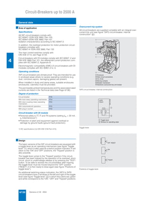
  • 1. Siemens LV 30 · 20044/130 Circuit-Breakers up to 2500 A General data 4 ■Area of application Specifications All 3VF circuit-breakers comply with: IEC 60947-1/DIN VDE 0660, Part 100; IEC 60947-2/DIN VDE 0660, Part 101. Isolation characteristics according to IEC 60947-3 In addition, the overload protection for motor protection circuit- breakers complies with: IEC 60947-4-1/DIN VDE 0660, Part 132. The main control switches comply with DIN VDE 0113, see Page 4/132. Circuit-breakers with DI modules comply with IEC 60947 -2 and DIN VDE 0660 Part 101, the differential current protection com- plies with IEC 60947-2, Appendix B. Electromagnetic compatibility (EMC) of circuit-breakers with DI modules complies with IEC 60801-2 to -5. Operating conditions 3VF circuit-breakers are climate proof. They are intended for use in enclosed areas where no severe operating conditions (e.g. dust, corrosive vapors, damaging gases) are present. When installed in dusty and damp areas, suitable enclosures (enclosures, cabinets) must be provided. The permissible ambient temperatures and the associated rated currents are listed in the Technical data (see Page 4/136). Degree of protection Circuit-breaker with DI module • Personal safety in TT, IT and TN systems (setting IΔn = 30 mA, td instantaneous)1) • Protection of plant and equipment against overload or damage by ground faults (ground fault protection). 1) IEC specifications (not DIN VDE 0100 Part 4/10). ■Design The basic versions of the 3VF circuit-breakers are equipped with a toggle lever as an operating mechanism (see figure "Toggle lever" ¿), which is also used as a switch position indicator. In ad- dition to the "ON" and "OFF" positions, the "Tripped" position is also possible. The toggle lever jumps to the "Tripped" position if the circuit- breaker has been tripped by the operation of its overload, short- circuit, shunt or undervoltage release or by pressing the "TEST"- button. To be able to reclose the circuit-breaker after tripping, the toggle lever must be moved beyond the "OFF" position ("RESET"). It is then ready to close again (see figure "Positions of toggle lever"). As additional switching status indication, the 3VF3 to 3VF8 circuit-breakers have 2 windows to the left and right of the toggle lever (see figure "Toggle lever" %) in which the colors red, green and white correspond to the "ON", "OFF" and "Tripped" positions. Overcurrent trip system All circuit-breakers are supplied complete with an integral over- current trip unit (see figure "3VF5 circuit-breaker, internal construction" *). 3VF5 circuit-breaker, internal construction Toggle lever Positions of toggle lever Circuit-breaker IP30 With front rotary operating mechanism IP54 With door-coupling rotary operating mechanism IP65 With motor/solenoid operation IP20 With plug-in socket IP20 N S E 0 _ 0 0 0 3 0 6 5 4 3 1 2 E n c l o s u r e M a i n c i r c u i t c o n n e c t i o n s A r c c h u t e M o v i n g c o n t a c t s B r e a k e r m e c h a n i s m E l e c t r o n i c o v e r c u r r e n t t r i p u n i t m o d u l e 1 2 3 4 5 6 1 O N O F F NSE0_00029 2 1 T o g g l e l e v e r 2 W i n d o w f o r o p e r a t i n g s t a t e NSE0_00031 O F F R E S E T O N T r i p p e d
  • 2. Siemens LV 30 · 2004 4/131 Circuit-Breakers up to 2500 A General data 4 Connection (See also Accessories, Page 4/182) The basic circuit-breakers are supplied as follows: With box terminals 3VF2 to 3VF5 circuit-breakers for the direct connection of stranded or finely-stranded conductors with end sleeves (see figure "Box terminals for 3VF3 and 3VF4" and Technical data). Box terminal for 3VF3 (left) and 3VF4 (right) Busbar connection pieces 3VF6 to 3VF8 circuit-breakers are connected using busbar con- nection pieces. These are designed for the connection of stan- dard busbars and are available for front or rear connection. Front busbar connection pieces for 3VF7 3VF6 circuit-breakers are supplied with front connection pieces. The connection of laminated flat copper bars using clamp termi- nations is possible with breaker types 3VF3 (up to 160 A), 3VF4, 3VF5, 3VF6 and 3VF7 (up to 800 A). The incoming and outgoing side can be chosen as desired for all circuit-breakers. The electrical data remains unchanged. An exception to this are circuit-breakers fitted with DI modules: these breakers must be fed from the top. Bare conductors and bars at the top connections must be insu- lated in the space above the arc chute (see dimension drawings on Page 4/191). Phase barriers (see Accessories, Pages 4/182 and 4/183) can also be used for this purpose. Installation type Fixed-mounting In the standard version Plug-in circuit-breakers Instead of box terminals, the circuit-breakers have 6 blade con- tacts and also a safety trip pin. This causes the breaker to be tripped if an attempt is made to unplug it while it is closed and prevents the breaker from being switched on before it is properly located in its socket. Withdrawable circuit-breakers 3VF6 and 3VF7 circuit-breakers are available in a withdrawable design. Withdrawable circuit-breakers cannot be fitted with mo- torized operating mechanisms. Connection accessories Two types of connection are possible for internally-fitted acces- sories (auxiliary releases, auxiliary switches) (see figure "Auxiliary release and auxiliary switch"): • With terminal block (on the side of the breaker) • With connecting leads (finely stranded) Motorized operating mechanisms always have connection ter- minals. Accessories All circuit-breakers are supplied complete with internally-fitted accessories according to order (e.g. auxiliary or alarm switches, undervoltage or shunt releases). The equipment options can be seen from the ordering tables on Page 4/174. Externally fitted accessories, such as rotary operating mechanisms, motorized operating mechanisms, connection accessories etc. are always supplied separately. Auxiliary release, auxiliary switch - connection with terminal strip (left) connection with connecting leads (right) Operating mechanisms (see also Page 4/178) Front-operated rotary operating mechanisms (figure "Front-op- erated rotary operating mechanism for 3VF3") These are designed for fitting directly on the circuit-breaker and convert the vertical toggle lever movement into a rotary motion (rotary operating mechanism with knob). Front-operated rotary operating mechanism for 3VF6 Leading auxiliary switch on closing "S4" for front-operated rotary operating mechanisms (figure below). If the circuit-breaker has a leading auxiliary switch, it is possible to apply voltage early to the undervoltage release and thus pre- pare the breaker for closing. Leading auxiliary switch after ON "S4" in front-operated rotary operating mechanism NSE0_000033 NSE0_00032 NSE0_00034 NSE0_00035 BNSE0_00036 0 1 0 1 S 4 L 1 , L 2 , L 3 S w i t c h O N c l o s e d o p e n L e a d i n g a u x i l i a r y s w i t c h O N , " S 4 " o n f r o n t r o t a r y d r i v e
  • 3. Siemens LV 30 · 20044/132 Circuit-Breakers up to 2500 A General data 4 Leading auxiliary switch "S5" on opening for front-operated rotary operating mechanisms (figure below) If a circuit-breaker has a leading auxiliary switch on opening, the leading deactivation of, for example, thyristors is possible. Leading auxiliary switch after OFF "S5" in front-operated rotary operating mechanism Door-coupling rotary operating mechanisms (see figure "Door- coupling rotary operating mechanism for 3VF4") (complete oper- ating mechanisms) Door coupling mechanisms in the 8UC6 range are available for fitting to circuit-breakers in control cabinets and distribution boards with doors and detachable covers. These are supplied as complete kits, including an articulated-shaft mechanism; see Page 4/189. With regard to the switching positions and the "RESET" opera- tion, the same applies to rotary operating mechanisms as to tog- gle levers. Indication is by the position of the knob (see figure "Position of toggle lever"). Door-coupling rotary operating mechanism for 3VF4 Front rotary operating mechanisms and door-coupling rotary operating mechanisms All rotary operating mechanisms can be locked in the "OFF" po- sition using padlocks. All 3VF circuit-breakers equipped with these mechanisms and with suitable terminal covers can there- fore be used as main switches in accordance with DIN VDE 0113. Motorized operating mechanisms (figure "Motorized operating mechanism for 3VF4") 3VF3 to 3VF8 circuit-breakers can be equipped with motorized operating mechanisms to permit remote-controlled opening and closing. Motorized operating mechanism for 3VF4 Synchronizable motorized operating mechanisms (stored energy operating mechanisms) For synchronizable rapid closing (tE < 80 ms) or for normal re- mote tripping, solenoid or stored energy operating mechanisms are available. Locking devices to accept padlocks are available as an option for motorized operating mechanisms and are generally fitted to stored energy and solenoid operating mechanisms. These pro- vide electrical and mechanical lockout of the mechanism. All re- motely-controlled mechanisms are provided with a manual oper- ation device that permits all switching operations to be performed locally. Auxiliary releases and auxiliary switches Undervoltage releases, leading auxiliary switches The circuit-breaker can only be closed if voltage is applied to the undervoltage release. If voltage is not applied to the release, op- eration of the circuit-breaker will result in no-load switching. Frequent re-tripping should be avoided because of its adverse effect on the service life of the circuit-breaker. If the circuit-breaker has a leading auxiliary switch, it is possible to apply voltage early to the undervoltage release and thus pre- pare the breaker for closing. For 3VF circuit-breakers, the leading auxiliary switch can be supplied with the front rotary operating mechanisms or complete operating mechanisms. See "Accessories" for more information. Time-delay device for undervoltage release To avoid tripping of the circuit-breaker during brief interruptions or drops in the voltage, delay devices can be fitted in the under- voltage release circuit. When selecting a circuit-breaker with de- layed undervoltage release, it must be noted that the voltage of the undervoltage release must be selected for DC. Shunt release The shunt release (f release) is used for remote tripping. The coil of the shunt release is designed for short-time operation only. It is not permissible to apply a continuous trip command to a shunt release to prevent closing when the circuit-breaker is tripped, i.e. interlocking circuits with a continuous command must not be designed to operate a shunt release. Auxiliary switches Auxiliary switches are used for indication and control. The vari- ous functions of the auxiliary switch (1 changeover) can be seen from the table. Alarm switches The alarm switch operates when the circuit-breaker is tripped by short-circuit or overcurrent, and also when tripped by the shunt release or undervoltage release. NSE0_01240 1 0 1 0 S 5 L 1 , L 2 , L 3 S w i t c h O F F c l o s e d o p e n L e a d i n g a u x i l i a r y s w i t c h O F F , " S 5 " o n f r o n t r o t a r y d r i v e
  • 4. Siemens LV 30 · 2004 4/133 Circuit-Breakers up to 2500 A General data 4 Options for equipping 3VF3 to 3VF8 circuit-breakers with auxiliary and alarm switches (for complete range of equipment options see Page 4/174). Operation of contacts of auxiliary and alarm switches depending on the switching status of the circuit-breaker Mounting of auxiliary and alarm switches (see Accessories, Page 4/174) The equipping of a circuit-breaker with auxiliary switches and alarm switches depends on the position in which these switches are fitted in the circuit-breaker and on the size of the circuit- breaker. The mounting position of the auxiliary switches and alarm switches differs according to the version of the circuit-breaker (see Page 4/174). PLC control Coupling units or contactor relays should be used to interface with a PLC. Circuit-breaker with DI module Displays/shunt release A visual indicator in the circuit-breaker cover and an auxiliary switch for remote monitoring indicate whether the circuit-breaker has been tripped by the DI trip unit. The DI trip unit can also be used as a shunt release for remote tripping of the circuit-breaker. The circuit-breaker and DI module combination is fed from the top. The 3VF circuit-breakers (3- and 4-pole) with DI module can be supplied with auxiliary and alarm switches (2nd Order No. supplement, see Pages 4/171 and 4/172). No undervoltage or additional shunt release is possible for cir- cuit-breakers with DI module (1st Order No. supplement: "0A", see Pages 4/171 and 4/172). 2 A S 1 A S 2 A S 2 A S 1 A S 2 A S 1 H S 1 A S 2 H S 1 A S + 1 H S 2 A S 1 H S 1 A S 2 H S 1 A S + 1 H S 1 H S 2 H S 2 H S 1 A S 1 A S 1 H S 2 H S 2 H S 2 H S 1 H S 1 H S N S E 0 0 0 3 7 b D I D I D I D I D I D I D I D I D I D I 2 A S 4 H S 2 A S 4 H S 2 A S 4 H S 2 A S 4 H S 2 A S 4 H S 2 A S 4 H S 1 H S 1 H S 1 ) 3 - p o l e c i r c u i t - b r e a k e r s 4 - p o l e c i r c u i t - b r e a k e r s l e f t r i g h t l e f t r i g h t 3 V F 3 f o r m o t o r p r o t e c t i o n A u x i l i a r y s w i t c h A l a r m s w i t c h F o r 3 V F 8 c i r c u i t - b r e a k e r s o n l y S h u n t r e l e a s e o r u n d e r v o l t a g e r e l e a s e o r D I m o d u l e ( i f b u i l t i n ) H S A S 1 ) A v a i l a b l e o n l y f o r 3 V F 3 . . . . - . . . . . - . . F 1 . 3 ( 6 ) 1 ( 4 ) 2 ( 5 ) 3 ( 6 ) 1 ( 4 ) 2 ( 5 ) 3 ( 6 ) 1 ( 4 ) 2 ( 5 ) 1 2 ( 2 2 ) 1 4 ( 2 4 ) 1 1 ( 2 1 ) 1 2 ( 2 2 ) 1 4 ( 2 4 ) 1 1 ( 2 1 ) 1 2 ( 2 2 ) 1 4 ( 2 4 ) 1 1 ( 2 1 ) 1 6 ( 2 6 ) 1 8 ( 2 8 ) 1 5 ( 2 5 ) 1 6 ( 2 6 ) 1 8 ( 2 8 ) 1 5 ( 2 5 ) 1 6 ( 2 6 ) 1 8 ( 2 8 ) 1 5 ( 2 5 ) 6 7 7 7 7 86 8 6 7 7 7 7 86 8 6 7 7 7 7 86 8 3 1 3 1 3 1 2 2 2 N S E 0 _ 0 1 2 4 1 6 3 7 3 7 46 4 6 3 7 3 7 46 4 6 3 7 3 7 46 4 P o s i t i o n o f t o g g l e l e v e r ( a l s o a p p l i e s t o r o t a r y o p e r a t i n g m e c h a n i s m ) O N T r i p p e d P o s i t i o n o f 3 V F 2 a u x i l i a r y s w i t c h e s P o s i t i o n o f 3 V F 2 a l a r m s w i t c h e s P o s i t i o n o f 3 V F 3 t o 3 V F 8 l e a d i n g a u x i l i a r y s w i t c h a f t e r O N O F F ( R E S E T ) 3 ) P o s i t i o n o f 3 V F 3 t o 3 V F 8 l e a d i n g a u x i l i a r y s w i t c h a f t e r O F F 3 ) 1 ) V a l u e s i n b r a c k e t s a p p l y t o s e c o n d s w i t c h b l o c k 2 ) T h e t e r m i n a l d e s i g n a t i o n s f o r t h e 3 r d a n d 4 t h a u x i l i a r y s w i t c h c a n b e s e e n f r o m t h e c i r c u i t d i a g r a m o n t h e I n t e r n e t u n d e r w w w . a d . s i e m e n s . d e / c s i / c d 3 ) I n t e g r a t e d i n r o t a r y o p e r a t i n g m e c h a n i s m s . P o s i t i o n o f 3 V F 3 t o 3 V F 8 a u x i l i a r y s w i t c h e s P o s i t i o n o f 3 V F 3 t o 3 V F 8 a l a r m s w i t c h e s 1 )1 ) 2 )
  • 5. Siemens LV 30 · 20044/134 Circuit-Breakers up to 2500 A General data 4 ■Functions 3VF2 to 3VF6 circuit-breakers for system protection with me- chanical overload and short-circuit release, i.e. overcurrent trip unit version "LI" The overload and short-circuit releases function with bimetallic or magnetic elements. They can be supplied as non-adjustable or adjustable units. Four-pole circuit-breakers for system protection can be supplied optionally with overcurrent trip units in all 4 poles or without over- current trip unit in the 4th pole (N). Above 100 A rated current the trip units in the 4th pole (N) are designed for 60 % of the current of the 3 main conductors to ensure safe protection for cables with reduced cross-section neutral conductors. Electronic overcurrent trip unit for system protection (example 3VF7) 3VF5 to 3VF8 system protection circuit-breakers with electronic overcurrent trip unit All 3VF7 to 3VF8 circuit-breakers are equipped with "LSI" elec- tronic overcurrent trip units for short-delay short-circuit tripping. The electronic overcurrent trip unit system consists of: • 3 current transformers • Evaluation electronics with microprocessor • Tripping solenoid. No auxiliary voltage supply is required for the release system. A minimum load current of approximately 20% of the corre- sponding rated current In of the circuit-breaker is required to ac- tivate the overcurrent trip unit. Fault-free operation of the overcurrent trip unit is indicated by the "heartbeat", a flashing LED ( ("ACTIVE") (see figure "Electronic overcurrent trip unit" (). A maintained light indicates an over- load condition I > 100 % In an. Inverse-time delayed overload tripping operation "L" The 3VF5 to 3VF8 circuit-breakers for system protection with electronic trip units have real r.m.s. current measuring and are therefore also suitable for use in networks with a high harmonic content. The harmonics are evaluated for overload protection in the usual manner. The set current Ir can be set from 0.5 to 1 times the value of the rated current In of the circuit-breaker in 4 increments. The time-lag class of the inverse-time delayed tripping operation corresponds to 10 s with 7.2 × Ir (see figure "Electronic overcur- rent trip unit" $). Short-time delayed short-circuit tripping operation "S" The operating value Id can be set in 7 increments between 2 and 8 times the value of Ir. The delay time td can be set from 0 (instantaneous) to 300 ms in 4 increments. This means that time-based discrimination to downstream cir- cuit-breakers can be achieved up to current values of - 4.0 kA ± 15% for 3VF5, - 5.5 kA ± 15% for 3VF5, - 15 kA ± 15% for 3VF7 and - 20 kA ± 15% for 3VF8. Instantaneous short-circuit tripping operation "I" The operating value Ii of the instantaneous short-circuit release is set to a fixed value of 4 kA for 3VF5, 5.5 kA for 3VF6, 15 kA for 3VF7 and 20 kA for 3VF8. The electronic circuit of the overcurrent trip unit is inherently safe at high temperatures: if the tempera- ture of the printed circuit board rises to 90 °C the circuit-breaker trips. Circuit-breakers for motor protection All circuit-breakers for motor protection are equipped with elec- tronic overcurrent trip units. These work on the same principle as the electronic overcurrent trip units fitted to the line protection circuit-breakers. The characteristic curve of the inverse-time delayed overcurrent trip unit is optimally matched to the overload behavior of three- phase motors. Depending on the version, the time lag character- istic of the overload release can be set in steps between "Class 5" and "Class 30". Phase failure sensitivity is also integrated into this version vari- ant, so that the motor is provided with reliable protection even in the event of phase failure or severe asymmetry. All 3VF3 to 3VF6 circuit-breakers for motor protection have a so- called "thermal memory" which stores the preload of the breaker and tripping history due to overload and takes account of the heating of the motor by reducing the tripping time. A cooling pe- riod of a few minutes may therefore be required following trip- ping due to overload before the motor can be re-started. The same applies if there are too many starts within a short pe- riod which can cause the motor to heat up excessively. A reclos- ing lockout remains in force for one minute following a trip on overload. In circuits with very high harmonic content caused by frequency converters or soft starters, 3VF2 to 3VF6 circuit-breakers with "LI" bimetal releases are recommended. Circuit-breakers for starter combinations Circuit-breakers for starter combinations are used in practice to- gether with a motor contactor and a matched overload relay. Non-automatic circuit-breakers Non-automatic circuit-breakers have integral short-circuit pro- tection so that back-up fuses are not required. 4-pole non-auto- matic circuit-breakers do not have a short-circuit release in the 4th pole (N). Circuit-breakers as main control switches to EN 60204 or DIN VDE 0113 in combination with lockable rotary operating mechanisms with terminal covers or as EMERGENCY-STOP switches to EN 60204 or DIN VDE 0113 in combination with red operating mechanisms on yellow backgrounds and undervolt- age releases, if required. 6 3 0 A 8 0 0 A 1 0 0 0 A 1 2 5 0 A r 1 5 k A d d i m s X > > > > N S E 0 _ 0 0 0 2 8 3 0 0 2 0 0 1 0 03 2 8 7 4 5 6 A C T I V E 41 2 3 1 2 3 4 N o n - d e l a y e d E l e c t r o n i c o v e r c u r r e n t t r i p u n i t C u r r e n t s e t t i n g O p e r a t i n g c u r r e n t D e l a y t i m e L E D f l a s h e s : F a u l t - f r e e o p e r a t i o n o f e l e c t r o n i c o v e r c u r r e n t t r i p u n i t ; L E D s t e a d y l i g h t : O v e r l o a d s t a t e r d d
  • 6. Siemens LV 30 · 2004 4/135 Circuit-Breakers up to 2500 A General data 4 Circuit-breaker with DI module The DI module detects ground fault currents in 3- and 4-wire systems (AC or pulsating DC) and causes the circuit-breaker to switch off the faulty circuit. Equipping a 3VF circuit-breaker with a DI module has no effect on the characteristics of the circuit-breaker: • Rated voltage (50/60 Hz), rated current, switching capacity • Electrical and mechanical life • Connections • Operating mechanisms • Auxiliary switches and releases. In a fault-free system, the sum of the conductor currents in the current transformer of the DI module is equal to zero. If a fault current flows to ground due to an insulation fault in the part of the system being protected, a differential current results. This pro- duces a voltage in the secondary winding of the current trans- former. The induced voltage is evaluated electronically and a trip signal is given to the DI trip unit in the circuit-breaker if the trip conditions are fulfilled. 3VF circuit-breaker with DI module Settings • The differential tripping current IΔn is adjustable in increments from 30 mA to 30 A. • The trip delay can be set from instantaneous to 1 sec in incre- ments. Exception: with setting IΔn = 30 mA, tripping is instantaneous. • The setting knob can be sealed to prevent unauthorized ac- cess. • The control panel incorporates a test button to electronically test the function of the current transformers, the evaluation electronics and the DI trip unit in the circuit-breaker. • The DI module detects 1, 2, 3 or 4-pole loads with its integral summation current transformer. ■Integration Installation Mounting the circuit-breakers in line without intermediate spac- ing is, in fact, possible but is not recommended because of the reduced heat dissipation (and possible reduction of current rat- ing).
  • 7. Siemens LV 30 · 20044/136 Circuit-Breakers up to 2500 A General data 4 ■Technical specifications Type 3VF2 Standards IEC 60947, EN 60947 Max. rated current In A 16 ... 100 Rated insulation voltage Ui Main circuits Control circuits AC V AC V 415 415 Rated impulse withstand voltage Uimp Main circuits Control circuits kV kV 6 4 Rated operating voltage Ue, 50/60 Hz IEC AC V up to 415 Permissible ambient temperature °C –20 ... +70 Permissible load at various ambient temperatures close to the circuit-breaker, related to the rated current of the circuit-breaker up to 100 A – Circuit-breakers for system protection at 40 °C % 100 50 °C % 92 55 °C % 87 60 °C % 83 70 °C % 73 Rated short-circuit breaking capacity Switching capacity class A Rated ultimate short-circuit breaking capacity Iu up to 240 V kA 65 up to 415 V kA 18 Rated service short-circuit breaking capacity Ics up to 240 V kA 33 up to 415 V kA 9 Rated short-circuit making capacity Icm up to 240 V kA 143 up to 415 V kA 36 Main control switch properties to IEC 60947-2 in conjunction with lockable rotary operating mechanisms yes EMERGENCY-STOP switch properties to DIN VDE 0113 yes Mechanical endurance Operating cycles 10000 Operating frequency 1/h 120 Conductor cross-sections and types of connec- tion for main conductors (copper or aluminum) Connection type Box terminal Solid or stranded up to 45 A mm2 2.5 ... 10 45 ... 100 A mm2 16 ... 50 125 A mm2 70 Tightening torque for box terminals Nm 4.0 (up to 40 A)/5.7 (45 ... 100 A) Conductor cross-sections for control circuits with terminal connection or terminal strip, solid mm2 0.5 ... 2.5 Tightening torque for terminal screws Nm 0.9 Power loss per circuit-breaker at max. rated current In with 3-phase symmetrical load – System protection W 16 Permissible mounting position Auxiliary switches Conventional thermal current Ith A 6 Rated making capacity A 15 AC (AC-15) – Rated operating voltage V 240 – Rated operating current A 6 DC (DC-13) – Rated operating voltage V 125 – Rated operating current A 0.5 Back-up fuse A 4 Trip units Shunt release (f-release) Operating voltage – Pick-up (circuit-breaker is tripped) Power input (short time) at: AC 50/60 Hz 12 ... 24 V VA 108 AC 50/60 Hz 48 ... 60 V VA 120 AC 50/60 Hz 48 ... 127 V VA 162 DC 12 ... 24 V W 14.4 DC 48 ... 60 V W 19.2 DC 110 ... 125 V W 38.4 DC 220 ... 250 V W 44 Max. duration of operating voltage interrupts automatically Max. opening time ms 50 90° 90° NSE0_00026 90° 90° NSE0_01242
  • 8. Siemens LV 30 · 2004 4/137 Circuit-Breakers up to 2500 A General data 4 1) For circuit-breakers with rated currents ≤ 40 A: Ue max. 415 V. 2) Circuit-breaker cannot be used for direct current. 3) Busbar connection pieces (see Accessories). 4) 800 A: 3 × 40 × 5. 5) Max. cross-section for one conductor only. For smaller cross-sections: sum up to max. cross-section can be connected. Use identical cross-sections. CupAI end sleeves/cable lugs or CupAI shims are recommended for con- necting aluminum conductors. 6) Also suitable for use in 400 Hz systems, technical specifications on request. 7) 10 kA for 3VF.. ..–0....–.... 8) 240 mm2 not suitable for segmented conductors as the terminal has an oval aperture. $ Thermal overload release set to the upper value, or permanently set ther- mal overload release. % Thermal overload release set to the lower value. & Electronic trip unit. Type 3VF3 3VF4 3VF5 3VF6 3VF7 3VF8 Max. rated current In AC/DC A 160; 205/225 200/250 315/400 500/630/800 800/1250 1600/2000 2500 depending on version Rated insulation voltage Ui to IEC 60947-2 Main circuits AC V 750 750 750 750 750 750 Control circuits AC V 690 690 690 690 690 690 Rated impulse withstand voltage Uimp Main circuits kV 8 Control circuits kV 4 Rated operating voltage Ue, 50/60 Hz IEC AC V 6901) 690 690 690 690 690 NEMA AC V 6001 ) 600 600 600 600 600 IEC DC V 750 750 750 750 –2 ) –2 ) Permissible ambient temperature °C –20 ... + 70 –5 ... + 60 Rated short-circuit breaking capacity (DC) not for 3VF motor protection circuit-breakers Time constant τ = 10 ms 1 current path 2 current paths in series 3 current paths in series 4 current paths in series for 3VF3 to 3VF6 up to DC 250 V DC 440 V DC 600 V DC 750 V kA 20/107 ) 20 20 20 –2 ) –2 ) NEMA Time constant τ = 8 ms 1 current path 2 current paths in series DC 250 V – kA 10 10 10 10 –2 ) –2 ) – DC 250 V kA 22/207 ) 22 22 22 –2 ) –2 ) Permissible load at various ambient temperatures close to the circuit-breaker, related to the rated current of the circuit-breaker $ % $ % $ % & $ % & $ & & – Circuit-breakers for system protection at 40 °C % 50 °C % 55 °C % 60 °C % 70 °C % 100 96 93 91 86 100 92 87 83 73 100 96 94 92 88 100 94 90 87 80 100 96 93 90 85 100 92 87 84 75 100 100 100 100 85 100 96 93 90 85 100 91 86 82 70 100 100 100 100 84 100 91 85 81 – 100 100 100 100 – 100 100 96 92 – – Circuit-breakers for motor protection at 40 °C % 50 °C % 55 °C % 60 °C % 70 °C % 100; 100 100; 96 100; 90 100; 86 100; 77 – – – – – 100 100 100 100 87 100 100 100 100 90 – – – – – – – – – – – Circuit-breakers for starter combinations and non-automatic circuit-breakers at 40 °C % 50 °C % 55 °C % 60 °C % 70 °C % 100 100 96 91 86 100 100 96 92 88 100 100 95 90 85 100 100 95 90 84 100 91 85 81 – 100 100 100 100 – 100 100 96 92 – Main control switch properties to IEC 60947-2 in conjunction with lockable rotary operating mechanisms yes yes yes yes yes yes EMERGENCY-STOP switch properties to DIN VDE 0113 yes yes yes yes yes yes Rated short-circuit breaking capacity to IEC 60947-2 (AC 50/60 Hz)6 ) See Page 4/141 for rated short-circuit breaking capacity. Mechanical endurance Operating frequency Operating cycles 1/h 10000 300 10000 240 8000 240 8000 240 3000 60 3000 20 Conductor cross-sections and types of connection for main conductors5 ) Connection type Box terminals Box terminals Box terminals Flat connector Flat connector Flat connector Mount busbars vertically Solid or stranded mm2 2.5 ... 70; 95 50 ... 150 95 ... 2408 ) – – – – Finely stranded with end sleeve mm2 2.5 ... 50; 70 35 ... 120 70 ... 150 – – – – Busbar mm – – – 1×40 × 104 ) 2×40×103 ) 2×60×103 )/ 3×80×10 Multiple feed-in terminal (accessory) 2×80×103 ) Cu or Al, stranded mm2 – – – 2×(185...240) 4×(95...185) – – Laminated flat copper, max. width mm 13 (max 160 A) 15 20 40 (max 630 A) 40 (max 800 A) – – Tightening torque for box terminals Nm 5/9 20 42 31 31 – – Tightening torque for busbar connection pieces Nm 4.5/4.5 15 30 6 50 37 20
  • 9. Siemens LV 30 · 20044/138 Circuit-Breakers up to 2500 A General data 4 1) 2 conductors can be connected. & Electronic trip unit. Type 3VF3 3VF4 3VF5 3VF6 3VF7 3VF8 Conductor cross-sections for control circuits1) with terminal connection or terminal strip Solid mm2 0.75 ... 2.5 0.75 ... 2.5 0.75 ... 2.5 0.75 ... 2.5 up ... 2×4 up ... 2×4 Finely stranded with end sleeve mm2 0.75 ... 2.5 0.75 ... 2.5 0.75 ... 2.5 0.75 ... 2.5 up ... 2×2.5 up ... 2×2.5 With brought-out cable ends mm2 0.82 (AWG 18) 0.82 (AWG 18) 0.82 (AWG 18) 0.82 (AWG 18) 0.82 (AWG 18) 0.82 (AWG 18) Tightening torque for terminal screws Nm 0.8 ... 1.4 0.8 ... 1.4 0.8 ... 1.4 0.8 ... 1.4 0.8 ... 1.4 0.8 ... 1.4 Power loss per circuit-breaker at max. rated current In with 3-phase symmetrical load (The power loss of the undervoltage release (r-release) must also be taken into account where applicable) & & – System protection W 60 75 175 75 255 120 87/210 135/240 400 – Non-automatic circuit-breakers W 45 75 107 160 87/210 135/240 400 – For starter combinations W 45 45 107 160 – – – – Motor protection W 60 – 75 120 – – – Permissible mounting position 90° 90° NSE0_00026 90° 90° NSE0_01242 Type 3VF3 3VF4 3VF5 3VF6 3VF7 3VF8 Auxiliary switches Conventional thermal current Ith A 6 6 6 6 6 6 Rated making capacity A 20 20 20 20 20 20 AC (AC-15) – Rated operating voltage V 230 415 690 230 415 690 230 415 690 230 415 690 230 415 690 230 415 690 – Rated operating current A 6 3 0.25 6 3 0.25 6 3 0.25 6 3 0.25 6 3 0.25 6 3 0.25 DC (DC-13) – Rated operating voltage V 24 125 240 24 125 240 24 125 240 24 125 240 24 125 240 24 125 240 – Rated operating current A 6 0.5 0.15 6 0.5 0.15 6 0.5 0.15 6 0.5 0.15 6 0.5 0.15 6 0.5 0.15 Back-up fuse A 6 4 4 6 4 4 6 4 4 6 4 4 6 4 4 6 4 4 Miniature circuit-breaker A 6 4 4 6 4 4 6 4 4 6 4 4 6 4 4 6 4 4 Leading auxiliary switches (only in combination with rotary operating mechanism) Continuous thermal current Ith A 2 – 16 Rated making capacity A 2 (inductive 0.5) – 60 AC p.f. 0.7 0.7 – Rated operating voltage V 220 – 380 – Rated operating current A 2 (inductive 0.5) – 6 – Rated breaking capacity A 2 – 60 Back-up fuse (quick) A 2 – 16 Trip units Undervoltage release (r-release) Operating voltage: – Drop (breaker trips) V 0.7 ... 0.35 Us 0.7 ... 0.35 Us 0.7 ... 0.35 Us 0.7 ... 0.35 Us 0.7 ... 0.35 Us 0.7 ... 0.35 Us – Pick-up (breaker can be closed) V 0.85 ... 1.1 Us 0.85 ... 1.1 Us 0.85 ... 1.1 Us 0.85 ... 1.1 Us 0.85 ... 1.1 Us 0.85 ... 1.1 Us Power consumption in continuous operation at: AC 50/60 Hz 12 V VA 2.5 1.6 1.6 1.6 1.9 2.9 AC 50/60 Hz 24 V VA 1.4 6.0 6.0 6.0 2.4 3.1 AC 50/60 Hz 48–60 V VA 1.2 ... 1.9 3.2 ... 5.5 3.2 ... 5.5 3.2 ... 5.5 2.3 ... 4.1 3.4 ... 6.0 AC 50/60 Hz 110–127 V VA 1.3 ... 1.7 2.2 ... 2.9 2.2 ... 2.9 2.2 ... 2.9 3.4 ... 4.2 3.3 ... 3.8 AC 50/60 Hz 208–240 V VA 2.2 ... 2.9 3.5 ... 4.6 3.5 ... 4.6 3.5 ... 4.6 4.8 ... 6.5 4.2 ... 7.2 AC 50/60 Hz 380–500 V VA 2.9 ... 5 3.9 ... 6.9 3.9 ... 6.9 3.9 ... 6.9 6.8 ... 12.0 3.8 ... 10.0 DC 12 V W 2.8 2.5 2.5 2.5 2.8 3.4 DC 24 V W 1.6 3.1 3.1 3.1 3.6 4.3 DC 48–60 V W 1.3–2.0 3.5 ... 5.4 3.5 ... 5.4 3.5 ... 5.4 3.5–6.5 4.8 ... 7.2 DC 110–125 V W 1.5 ... 1.9 3.2 ... 4.1 3.2 ... 4.1 3.2 ... 4.1 2.9 ... 3.6 3.3 ... 3.8 DC 220–250 V W 2.6 ... 3.4 5.5 ... 6.9 5.5 ... 6.9 5.5 ... 6.9 4.8 ... 6.3 6.6 ... 7.5 Max. opening time ms 50 50 50 50 80 80 Shunt release (f-release) Operating voltage – Pick-up (circuit-breaker is tripped) V 0.7 ... 1.1 Us 0.7 ... 1.1 Us 0.7 ... 1.1 Us 0.7 ... 1.1 Us 0.7 ... 1.1 Us 0.7 ... 1.1 Us Power input (short time) at: AC 50/60 Hz 12–24 V VA 40 ... 300 87 ... 405 87 ... 405 81 ... 701 86 ... 631 177 ... 1207 AC 50/60 Hz 48–60 V VA – 710 ... 1105 710 ... 1105 58 ... 90 48 ... 71 443 ... 731 AC 50/60 Hz 48–127 V VA 92 ... 640 – – – – – AC 50/60 Hz 110–240 V VA 51 ... 240 66 ... 432 66 ... 432 118 ... 665 81 ... 505 323 ... 1466 AC 50/60 Hz 380–440 V VA – 127 ... 188 127 ... 188 125 ... 181 43 ... 68 1193 ... 1641 AC 50/60 Hz 380–600 V VA 278 ... 700 – – – – – AC 50/60 Hz 480–600 V VA – 34 ... 60 34 ... 60 43 ... 79 41 ... 69 197 ... 312 DC 12–24 V W 54 ... 400 164 ... 631 164 ... 631 79 ... 1000 46 ... 405 289 ... 865 DC 48–60 V W 100 ... 160 830 ... 1580 830 ... 1580 18 ... 31 58 ... 94 468 ... 696 DC 110–125 V W 55 ... 71 112 ... 150 112 ... 150 112 ... 150 74 ... 98 363 ... 473 DC 220–250 V W 110 ... 140 40 ... 58 40 ... 58 38 ... 52 38 ... 49 513 ... 665 Max. duration of operating voltage S interrupted automatically Max. opening time ms 50 50 50 50 62 62
  • 10. Siemens LV 30 · 2004 4/139 Circuit-Breakers up to 2500 A General data 4 Back-up fuses according to UL/CSA for "General Use Switch" In conformance with Approval File E167267, 3VF circuit-breakers to UL 508 are only permitted to be operated with the following UL- or CSA-approved back-up fuses up to AC 600 V: ■Technical specifications Type Rated current "L" In A max. UL back-up fuse (AC 600 V) A 3VF31 31–.FL41–.... 50 200 3VF31 31–.FN41–.... 60 225 3VF31 31–.FQ41–.... 80 300 3VF31 31–.FS41–.... 100 400 3VF42 31–.DF41–.... 125 500 3VF42 31–.DH41–.... 150 600 3VF42 31–.DK41–.... 200 800 3VF42 31–.DM41–.... 250 1000 3VF52 31–.DF41–.... 200 800 3VF52 31–.DH41–.... 250 1000 3VF62 31–.DF41–.... 300 1200 3VF62 31–.DH41–.... 400 1600 3VF62 31–.DK41–.... 500 2000 Type 3VF3 3VF4 3VF5 3VF6 3VF7 3VF8 Motorized operating mechanism Power input W 200 200 200 300 1000 2000 Rated control voltage AC 50/60 Hz V – 42 – 110–127 220–240 110–127 220–240 110–127 220–240 DC V 24 48 60 110 220 48 110 48 – Back-up fuse or miniature circuit-breaker A 10 (for 6 (for 6 6 6 3VF6: 16 A) 3VF6: 10 A) 25 (for DC 32 (A) 16 32 20 Operating range V 0.85 ... 1.1 Us 0.85 ... 1.1 Us 0.85 ... 1.1 Us 0.85 ... 1.1 Us 0.85 ... 1.1 Us 0.85 ... 1.1 Us Minimum command duration at Us s 1 1 1 1 0.5 0,03 Max. make- or break-time s 1 1 1 1 0.5 0.5 Reclosure after approx. s 2 2 2 2 60 60 Max. permissible switching fre- quency 1/h 120 120 60 60 (4-pole: 20) 60 20 Max. command duration s Non-maintained or continuous signal (depends on circuit) Synchronized motorized operating mechanism Power input W – 200 200 300 – – Rated control voltage AC 50/60 Hz V – – 42 – 110 ... 127 220 ... 240 – – DC V 24 48 60 110 220 Back-up fuse or miniature circuit-breaker A – 10 6 (for 6 6 6 3VF6: 10 A) – – Operating range V – 0.85 ... 1.1 Us 0.85 ... 1.1 Us 0.85 ... 1.1 Us – – Minimum command duration at Us ms – 45 45 45 – – Total make-time ms – 50 50 50 – – Break-time S – 1 1 1 – – Charging time S – 2 2 2 – – Reclosure after approx. S – 3 3 3 – – Max. permissible switching fre- quency 1/h – 60 60 60 (4-pole: 20) – – Max. command duration S – Non-maintained or continuous signal (depends on circuit) Solenoid operating mechanism Making current at rated operating voltage AC 110–120 V, DC 110–120 V A 20 – – – – – AC 220–240 V, DC 220–240 V A 11 Back-up fuse AC 110–120 V, DC 110–120 V A 6 AC 220–240 V, DC 220–240 V A 4 Operating range V 0.85 ... 1.1 Us – – – – – Minimum command duration at Us ms 30 Max. make- or break-time ms 80 Minimum necessary interval after make- break operation s 15
  • 11. Siemens LV 30 · 20044/140 Circuit-Breakers up to 2500 A General data 4 Switching of DC currents The 3VF3 to 3VF6 circuit-breakers for system protection with overcurrent trip unit versions "LI" can also be used to switch DC currents. The 3VF5 to 3VF8 circuit-breakers for system protection with overcurrent trip unit version "LSI" and 3VF for motor protection are not suitable for DC currents because of their electronic over- load release. However, the maximum permitted DC voltage for each current path needs to be taken into account for DC switching applica- tions. For higher voltages, 2 or 3 current paths must be connected in series. If 4 current paths are connected in series, it must be en- sured that the 4th pole (N) does not have an overload and short- circuit release (see Page 4/160 and 4/166, footnote 2). Since all current paths must carry a current to comply with the thermal tripping characteristics, we suggest implementation of the following circuits. With DC applications, the response values of the instantaneous short-circuit releases ("I" trip units) are in- creased by 30 to 40 %. Correlation between the short-circuit making capacity, the short-circuit breaking capacity and the corresponding power factor (to IEC 60947-2) Recommended circuit configuration Max. permissible DC voltage Ue Note For 3 and 4-pole circuit-breakers DC 250 V 2-pole switching If there is no possibility of a ground fault, or if every ground fault is rectified immediately (ground-fault monitoring), then the maximum permitted DC volt- age is 600 V. DC 440 V 2-pole switching (grounded system) The grounded pole is always assigned to the individual current path, so that there are always 2 current paths in series in the event of a ground fault. DC 600 V 1-pole switching (grounded system) 3 current paths in series. The grounded pole is assigned to the unconnected current path. DC 750 V 1-pole switching (grounded system) 4 current paths in series. The grounded pole is assigned to the unconnected current path. L NSE0_00741 M L L NSE0_00742 M L L NSE0_00743 M L L L NSE0_00744 M Short-circuit breaking capacity I A Power factor p.f. Minimum value for short-circuit making capacity (n times short-circuit breaking capacity) n × I 4500 < I ≤ 6000 0.7 1.5 × I 6000 < I ≤ 10000 0.5 1.7 × I 10000 < I ≤ 20000 0.3 2.0 × I 20000 < I ≤ 50000 0.25 2.1 × I 50000 < I 0.2 2.2 × I
  • 12. Siemens LV 30 · 2004 4/141 Circuit-Breakers up to 2500 A General data 4 Rated short-circuit breaking capacity Rated ultimate short-circuit breaking capacity Icu and rated service short-circuit breaking capacity Ics 1) 3VF3 circuit-breakers with rated currents In up to 40 A; max. rated operating voltage Ue = AC 500 V (3VF31 13, 3VF31 14 circuit-breakers). 2) Values in brackets for circuit-breakers for starter combinations 3) Values apply to non-automatic circuit-breakers only. 4) 225 A: for non-automatic circuit-breakers only. 5) 205/225 A: with AC 690 V Icu = 14 kA, Ics = 7 kA. Type 3VF3 3VF5 3VF6 Rated current In A 205 315 500 3VF circuit-breakers for motor protection up to AC 220/240 V Icu kA 85 100 65 100 65 100 Ics kA 85 100 33 50 33 50 up to AC 380/415 V Icu kA 40 70 40 65 40 65 Ics kA 40 70 20 33 20 33 up to AC 440 V Icu kA 25 40 35 50 35 50 Ics kA 13 20 18 25 18 25 up to AC 500 V Icu kA 18 25 30 42 30 42 Ics kA 9 13 15 21 15 21 up to AC 690 V Icu kA 12 14 20 25 20 25 Ics kA 6 7 10 13 10 13 Type 3VF2 3VF3 3VF31 ) 3VF4 3VF5 3VF6 3VF6 3VF7 3VF8 Rated current In 125 160 160/2005)2255) 250 400 630 800 800/1250 1600/2000/ 2500 3VF circuit-breakers for system protection up to AC 220/240 V Icu kA 65 40 85 100 200 85 100 200 85 100 200 85 100 200 65 85 100 200 135 200 Ics kA 40 40 85 100 150 85 100 150 85 100 150 85 100 150 33 85 100 100 100 100 up to AC 380/415 V Icu kA 18 25 40 70 100 40 70 100 45 70 100 45 70 100 50 50 70 100 70 100 Ics kA 9 25 40 70 75 40 70 75 45 70 75 45 70 75 25 50 50 50 50 50 up to AC 440 V Icu kA – – 25 40 65 25 50 80 35 50 80 35 50 80 35 35 50 80 50 80 Ics kA – – 13 20 33 13 25 40 18 25 40 18 25 40 18 18 25 40 25 40 up to AC 500 V Icu kA – – 18 25 50 20 42 65 30 42 65 30 42 65 35 30 42 65 42 65 Ics kA – – 9 13 25 10 21 33 15 21 33 15 21 33 18 15 21 33 21 33 up to AC 690 V Icu kA – – 121) 141) 181)5) 14 18 22 20 25 35 20 25 35 20 20 25 35 25 35 Ics kA – – 61 ) 71 ) 61 )5 ) 7 9 11 10 13 18 10 13 18 10 10 13 18 13 18 Type 3VF3 3VF4 3VF5 3VF6 3VF7 3VF8 Rated current In A 160/2254 ) 250 (200)2 ) 315/400 500/630 800/1250 1600/2000 3VF circuit-breakers for starter combinations 3VF non-automatic circuit-breakers up to AC 220/240 V Icu kA 100 853 ) 100 653 ) 100 653 ) 100 853 ) 1003 ) 1253 ) Ics kA 100 853) 100 333) 50 333) 50 853) 1003) 633) up to AC 380/415 V Icu kA 70 403 ) 70 403 ) 65 403 ) 65 503 ) 703 ) 653 ) Ics kA 70 403 ) 70 203 ) 33 203 ) 33 503 ) 503 ) 333 ) up to AC 440 V Icu kA 40 253 ) 50 353 ) 50 353 ) 50 353 ) 503 ) 503 ) Ics kA 20 133) 25 183) 25 183) 25 183) 253) 253) up to AC 500 V Icu kA 25 203) 42 303) 42 303) 42 303) 423) 423) Ics kA 13 103 ) 21 153 ) 21 153 ) 21 153 ) 213 ) 213 ) up to AC 690 V Icu kA 14 143) 18 203) 25 203) 25 203) 253) 253) Ics kA 7 73 ) 9 103 ) 13 103 ) 13 103 ) 133 ) 133 )
  • 13. Siemens LV 30 · 20044/142 Circuit-Breakers up to 2500 A 3-pole, fixed-mounted design 4 ■Selection and ordering data Pack size for 3VF is one unit, i.e. one unit or a multiple thereof can be ordered. For shunt releases and auxiliary/alarm switches see Accessories, Page 4/173. System protection, TM 3VF2 circuit-breakers, up to 18 kA Making/breaking capacity class A Rated ultimate short-circuit breaking capacity Icu up to 240 V up to 415 V kA kA 65 18 Rated service short-circuit breaking capacity Ics up to 240 V up to 415 V kA kA 33 9 Rated short-circuit making capacity Icm up to 240 V up to 415 V kA kA 143 38 Rated current In Setting current of the inverse-time delayed overload release "L" Ir Operating current of instantaneous short-circuit release "I" Ii DT VF100 circuit-breaker Making/breaking capacity class A Weight per PU approx. A A A Order No. kg With permanently set thermal overload releases 16 16 350 B 3VF22 13–0FC41–0AA0 0.948 20 20 450 B 3VF22 13–0FD41–0AA0 0.953 25 25 500 B 3VF22 13–0FE41–0AA0 0.961 32 32 600 B 3VF22 13–0FG41–0AA0 0.949 40 40 750 B 3VF22 13–0FJ41–0AA0 0.973 45 45 750 B 3VF22 13–0FK41–0AA0 0.960 50 50 800 B 3VF22 13–0FL41–0AA0 0.963 63 63 800 B 3VF22 13–0FN41–0AA0 0.967 70 70 900 B 3VF22 13–0FP41–0AA0 0.980 80 80 900 B 3VF22 13–0FQ41–0AA0 0.976 90 90 1000 B 3VF22 13–0FR41–0AA0 0.968 100 100 1000 B 3VF22 13–0FS41–0AA0 0.977 NSE0_00695
  • 14. Siemens LV 30 · 2004 4/143 Circuit-Breakers up to 2500 A 3-pole, fixed-mounted design 4 Pack size for 3VF is one unit, i.e. one unit or a multiple thereof can be ordered. For accessories, see from Page 4/174 onwards. Auxiliary releases and auxiliary/alarm switches to be retrofitted by the customer. System protection, TM 3VF3 circuit-breaker, up to 25 kA Making/breaking capacity class A Rated ultimate short-circuit breaking capacity Icu up to 240 V up to 415 V kA kA 40 25 Rated service short-circuit breaking capacity Ics up to 240 V up to 415 V kA kA 40 25 Rated short-circuit making capacity Icm up to 240 V up to 415 V kA kA 84 52 Rated current In Setting current of the inverse-time delayed overload release "L" Ir Operating current of instantaneous short-circuit release "I" Ii DT 3VF3 circuit-breaker Weight per PU approx. Order No. A A A kg With permanently set thermal overload releases 16 16 400 B 3VF31 13–0FC41–0AA0 2.300 20 20 400 B 3VF31 13–0FD41–0AA0 2.300 25 25 400 B 3VF31 13–0FE41–0AA0 2.300 32 32 400 B 3VF31 13–0FG41–0AA0 2.300 40 40 400 B 3VF31 13–0FJ41–0AA0 2.300 50 50 400 B 3VF31 11–0FL41–0AA0 2.300 63 63 500 B 3VF31 11–0FN41–0AA0 2.300 80 80 630 B 3VF31 11–0FQ41–0AA0 2.300 100 100 800 B 3VF31 11–0FS41–0AA0 2.300 125 125 1000 B 3VF32 11–0FU41–0AA0 2.300 160 160 1280 B 3VF32 11–0FW41–0AA0 2.300 NSE0_00695
  • 15. Siemens LV 30 · 20044/144 Circuit-Breakers up to 2500 A 3-pole, fixed-mounted design 4 Pack size for 3VF is one unit, i.e. one unit or a multiple thereof can be ordered. For degree of protection IP30, terminal covers are recom- mended in addition (see Pages 4/182 to 4/185). 1) Front busbar connection pieces are included in the scope of supply and are to be fitted by the customer. 2) 50 kA at AC 380/415 V. 3VF3 to 3VF6 circuit-breakers Type Rated current In Setting current of the inverse- time delayed overload release "L" Ir Operating current of the instanta- neous short- circuit release "I" Ii DT Standard switching capacity 40/45/50 kA at AC 380/415 V Fixed-mounted circuit-breakers Weight per PU approx. Order No. A A A Order No. supplements, see Pages 4/171 and 4/172. kg System protection, TM Circuit-breakers with permanently set thermal overload releases; for In up to 40 A: Ue max. AC 415 A 3VF3 16 20 25 32 40 16 20 25 32 40 400 400 400 400 400 B B B B B 3VF31 13–1FC41–.... 3VF31 13–1FD41–.... 3VF31 13–1FE41–.... 3VF31 13–1FG41–.... 3VF31 13–1FJ41–.... 2.300 2.300 2.300 2.300 2.300 50 63 80 100 50 63 80 100 400 500 630 800 B B B B 3VF31 11–1FL41–.... 3VF31 11–1FN41–.... 3VF31 11–1FQ41–.... 3VF31 11–1FS41–.... 2.300 2.300 2.300 2.300 125 160 125 160 1000 1280 B B 3VF32 11–1FU41–.... 3VF32 11–1FW41–.... 2.300 2.300 200 225 200 225 2400 2400 B B 3VF33 11–1FX41–.... 3VF33 11–1FY41–.... 2.300 2.300 3VF4 125 160 200 250 125 160 200 250 625–1250 800–1600 1000–2000 1250–2500 B B B B 3VF42 11–1DF41–.... 3VF42 11–1DH41–.... 3VF42 11–1DK41–.... 3VF42 11–1DM41–.... 4.200 4.200 4.200 4.200 3VF5 200 250 315 400 200 250 315 400 1000–2000 1250–2500 1575–3150 2000–4000 B B B B 3VF52 11–1DF41–.... 3VF52 11–1DH41–.... 3VF52 11–1DK41–.... 3VF52 11–1DM41–.... 5.500 5.500 5.500 5.500 3VF6 315 400 500 630 315 400 500 630 1575–3150 2000–4000 2500–5000 3150–6300 B B B B 3VF62 11–1DF44–.... 3VF62 11–1DH44–.... 3VF62 11–1DK44–.... 3VF62 11–1DM44–.... 8.400 8.400 8.400 8.400 1) 1) 1 ) 1) 800 800 3200–6400 B 3VF63 11–2DQ44–.... 8.400 1 )2 ) Circuit-breakers with adjustable thermal overload releases 3VF3 50 63 80 100 40– 50 50– 63 63– 80 80–100 300– 500 315– 630 400– 800 500–1000 B B B B 3VF31 11–1BL41–.... 3VF31 11–1BN41–.... 3VF31 11–1BQ41–.... 3VF31 11–1BS41–.... 2.300 2.300 2.300 2.300 125 160 100–125 125–160 625–1250 800–1600 B B 3VF32 11–1BU41–.... 3VF32 11–1BW41–.... 2.300 2.300 200 160–200 1000–2000 B 3VF33 11–1BX41–.... 2.300 3VF4 125 160 200 250 100–125 125–160 160–200 200–250 625–1250 800–1600 1000–2000 1250–2500 B B B B 3VF42 11–1BF41–.... 3VF42 11–1BH41–.... 3VF42 11–1BK41–.... 3VF42 11–1BM41–.... 4.200 4.200 4.200 4.200 3VF5 200 250 315 400 160–200 200–250 250–315 315–400 1000–2000 1250–2500 1575–3150 2000–4000 B B B B 3VF52 11–1BF41–.... 3VF52 11–1BH41–.... 3VF52 11–1BK41–.... 3VF52 11–1BM41–.... 5.500 5.500 5.500 5.500 3VF6 315 400 500 630 250–315 315–400 400–500 500–630 1575–3150 2000–4000 2500–5000 3150–6300 B B B B 3VF62 11–1BF44–.... 3VF62 11–1BH44–.... 3VF62 11–1BK44–.... 3VF62 11–1BM44–.... 8.400 8.400 8.400 8.400 1 ) 1 ) 1) 1 ) 3VF5 circuit-breaker for fixed mounting 3VF5 plug-in circuit-breaker with plug-in base (for plug-in bases see Pages 4/182 to 4/185) NSE0_00695 NSE0_00015 NSE0_00704
  • 16. Siemens LV 30 · 2004 4/145 Circuit-Breakers up to 2500 A 3-pole, fixed-mounted design 4 DT High switching capacity 70 kA at AC 380/415 V DT Very high switching capacity 100 kA at AC 380/415 V Fixed-mounted circuit-breakers Weight per PU approx. Fixed-mounted circuit-breakers Weight per PU approx. Order No. Order No. Order No. supplements, see Pages 4/171 and 4/172. kg Order No. supplements, see Pages 4/171 and 4/172. kg B B B B B 3VF31 13–2FC41–.... 3VF31 13–2FD41–.... 3VF31 13–2FE41–.... 3VF31 13–2FG41–.... 3VF31 13–2FJ41–.... 2.300 2.300 2.300 2.300 2.300 B B – – – 3VF31 13–3FG41–.... 3VF31 13–3FJ41–.... 2.300 2.300 B B B B 3VF31 11–2FL41–.... 3VF31 11–2FN41–.... 3VF31 11–2FQ41–.... 3VF31 11–2FS41–.... 2.300 2.300 2.300 2.300 B B B B 3VF31 11–3FL41–.... 3VF31 11–3FN41–.... 3VF31 11–3FQ41–.... 3VF31 11–3FS41–.... 2.300 2.300 2.300 2.300 B B 3VF32 11–2FU41–.... 3VF32 11–2FW41–.... 2.300 2.300 B B 3VF32 11–3FU41–.... 3VF32 11–3FW41–.... 2.300 2.300 B B 3VF33 11–2FX41–.... 3VF33 11–2FY41–.... 2.300 2.300 B B 3VF33 11–3FX41–.... 3VF33 11–3FY41–.... 2.300 2.300 B B B B 3VF42 11–2DF41–.... 3VF42 11–2DH41–.... 3VF42 11–2DK41–.... 3VF42 11–2DM41–.... 4.200 4.200 4.200 4.200 B B B B 3VF42 11–3DF41–.... 3VF42 11–3DH41–.... 3VF42 11–3DK41–.... 3VF42 11–3DM41–.... 4.200 4.200 4.200 4.200 B B B B 3VF52 11–2DF41–.... 3VF52 11–2DH41–.... 3VF52 11–2DK41–.... 3VF52 11–2DM41–.... 5.500 5.500 5.500 5.500 B B B B 3VF52 11–3DF41–.... 3VF52 11–3DH41–.... 3VF52 11–3DK41–.... 3VF52 11–3DM41–.... 5.500 5.500 5.500 5.500 B B B B 3VF62 11–2DF44–.... 3VF62 11–2DH44–.... 3VF62 11–2DK44–.... 3VF62 11–2DM44–.... 8.400 8.400 8.400 8.400 1) 1) 1 ) 1) B B B B 3VF62 11–3DF44–.... 3VF62 11–3DH44–.... 3VF62 11–3DK44–.... 3VF62 11–3DM44–.... 8.400 8.400 8.400 8.400 1) 1) 1 ) 1) – – B B B B 3VF31 11–2BL41–.... 3VF31 11–2BN41–.... 3VF31 11–2BQ41–.... 3VF31 11–2BS41–.... 2.300 2.300 2.300 2.300 B B B B 3VF31 11–3BL41–.... 3VF31 11–3BN41–.... 3VF31 11–3BQ41–.... 3VF31 11–3BS41–.... 2.300 2.300 2.300 2.300 B B 3VF32 11–2BU41–.... 3VF32 11–2BW41–.... 2.300 2.300 B B 3VF32 11–3BU41–.... 3VF32 11–3BW41–.... 2.300 2.300 B 3VF33 11–2BX41–.... 2.300 B 3VF33 11–3BX41–.... 2.300 B B B B 3VF42 11–2BF41–.... 3VF42 11–2BH41–.... 3VF42 11–2BK41–.... 3VF42 11–2BM41–.... 4.200 4.200 4.200 4.200 B B B B 3VF42 11–3BF41–.... 3VF42 11–3BH41–.... 3VF42 11–3BK41–.... 3VF42 11–3BM41–.... 4.200 4.200 4.200 4.200 B B B B 3VF52 11–2BF41–.... 3VF52 11–2BH41–.... 3VF52 11–2BK41–.... 3VF52 11–2BM41–.... 5.500 5.500 5.500 5.500 B B B B 3VF52 11–3BF41–.... 3VF52 11–3BH41–.... 3VF52 11–3BK41–.... 3VF52 11–3BM41–.... 5.500 5.500 5.500 5.500 B B B B 3VF62 11–2BF44–.... 3VF62 11–2BH44–.... 3VF62 11–2BK44–.... 3VF62 11–2BM44–.... 8.400 8.400 8.400 8.400 1 ) 1) 1 ) 1) B B B B 3VF62 11–3BF44–.... 3VF62 11–3BH44–.... 3VF62 11–3BK44–.... 3VF62 11–3BM44–.... 8.400 8.400 8.400 8.400 1 ) 1) 1 ) 1) 3VF6 circuit-breaker, with front busbar connec- tion pieces 3VF7 circuit-breaker Busbar connection pieces must be ordered separately
  • 17. Siemens LV 30 · 20044/146 Circuit-Breakers up to 2500 A 3-pole, fixed-mounted design 4 Pack size for 3VF is one unit, i.e. one unit or a multiple thereof can be ordered. For degree of protection IP30, terminal covers are recom- mended in addition (see Pages 4/182 to 4/185). 1) Front busbar connection pieces are included in the scope of supply and are to be fitted by the customer. 2) Busbar connection pieces or multiple feed-in terminals must be ordered separately (see Accessories). 3) Rear busbar connection pieces are included in the scope of supply and are to be fitted vertically. 4) Operating value of the short-time delayed short-circuit release 2 to 8 × Ir and 0 to 300 ms. 3VF5 to 3VF8 circuit-breakers Type Rated current In Setting current of the inverse- time delayed overload release "L" Ir Operating current of the short-time delayed short-circuit release "S" Id Operating time of the short-time delayed short-circuit release "S" td Operating current of the instan- taneous short-cir- cuit release "I" Ii DT Standard switching capacity 40/45/50 kA at AC 380/415 V Fixed-mounted circuit-breakers Weight per PU approx. Order No. A A A ms A Order No. supplements, see Pages 4/171 and 4/172. kg System protection, ETU Circuit-breakers with adjustable thermal overload releases 3VF5 With time-based discrimination 400 200, 250, 315, 400 2 ... 8 × Ir 0 ... 300 4000 B 3VF52 11–1BM61–.... 5.500 3VF6 630 315, 400, 500, 630 2 ... 8 × Ir 0 ... 300 5500 B 3VF62 11–1BM64–.... 8.400 1 ) 3VF7 800 1250 400, 500, 630, 800 630, 800, 1000, 1250 2 ... 8 × Ir 2 ... 8 × Ir 0 ... 300 0 ... 300 150004 ) 150004 ) B B 3VF71 11–1BK60–.... 3VF72 11–1BM60–.... 19.600 19.600 2 ) 2 ) 3VF8 1600 2000 2500 800, 1000, 1250, 1600 1000, 1250, 1600, 2000 1600, 1800, 2000, 2500 2 ... 8 × Ir 2 ... 8 × Ir 2 ... 8 × Ir 0 ... 300 0 ... 300 0 ... 300 200004 ) 200004 ) 200004 ) – 3VF5 circuit-breaker for fixed mounting 3VF5 plug-in circuit-breaker with plug-in base (for plug-in bases see Pages 4/182 to 4/185) L S I NSE0_00008
  • 18. Siemens LV 30 · 2004 4/147 Circuit-Breakers up to 2500 A 3-pole, fixed-mounted design 4 DT High switching capacity 70 kA at AC 380/415 V DT Very high switching capacity 100 kA at AC 380/415 V Fixed-mounted circuit-breakers Weight per PU approx. Fixed-mounted circuit-breakers Weight per PU approx. Order No. Order No. Order No. supplements, see Pages 4/171 and 4/172. kg Order No. supplements, see Pages 4/171 and 4/172. kg B 3VF52 11–2BM61–.... 5.500 B 3VF52 11–3BM61–.... 5.500 B 3VF62 11–2BM64–.... 8.400 1 ) B 3VF62 11–3BM64–.... 8.400 1 ) B B 3VF71 11–2BK60–.... 3VF72 11–2BM60–.... 19.600 19.600 2 ) 2 ) B B 3VF71 11–3BK60–.... 3VF72 11–3BM60–.... 19.600 19.600 2 ) 2 ) B B B 3VF82 11–2BM60–.... 3VF83 11–2BM60–.... 3VF84 11–2BM64–.... 49.000 50.000 50.000 2 ) 2 ) 3 ) B B B 3VF82 11–3BM60–.... 3VF83 11–3BM60–.... 3VF84 11–3BM64–.... 49.000 50.000 50.000 2 ) 2 ) 3 ) 3VF6 circuit-breaker, with front busbar connec- tion pieces 3VF7 circuit-breaker Busbar connection pieces must be ordered separately
  • 19. Siemens LV 30 · 20044/148 Circuit-Breakers up to 2500 A 3-pole, fixed-mounted design 4 Pack size for 3VF is one unit, i.e. one unit or a multiple thereof can be ordered. For degree of protection IP30, terminal covers are recom- mended in addition (see Pages 4/182 to 4/185). 1) Guide values for 4-pole standard motors. The start-up data and ratings of the motor to be protected are the determining factors. 2) System protection circuit-breakers must be used in combination with fre- quency converters or soft starters. 3) Front busbar connection pieces are included in the scope of supply and are to be fitted by the customer. 4) Busbar connection pieces must be ordered separately (see Accessories). 3VF3 to 3VF8 circuit-breakers Type Rated current In Rating of the three-phase motors to be protected1) at AC 50 Hz Setting cur- rent of the inverse-time delayed over- load release "L" Ir Operating current of the instanta- neous short- circuit release "I" Ii Time lag class Tc DT Standard switching capacity 40/50 kA at AC 380/415 V Fixed-mounted circuit-breakers Weight per PU approx. 380/ 415 V up to kW 500 V up to kW Order No. Order No. supplements, see Pages 4/171 and 4/172.A A A kg Motor protection, ETU2 ) without adjustable time lag class, without phase failure sensitivity 3VF3 80 100 160 205 37 45 75 110 55 55 110 132 40– 80 80–100 100–160 160–205 15 × Ir 15 × Ir 15 × Ir 13 × Ir 10 10 10 10 B B B B 3VF31 11–5DN71–.... 3VF31 11–5DQ71–.... 3VF32 11–5DS71–.... 3VF33 11–5DU71–.... 2.300 2.300 2.300 2.300 3VF5 315 160 200 160–315 15 × Ir 20 B 3VF51 11–5DL71–.... 4.200 3VF6 500 250 355 250–500 15 × Ir 20 B 3VF61 11–5DL74–.... 4.200 3) with adjustable time lag class, with phase failure sensitivity 3VF3 80 100 160 205 37 45 75 110 55 55 110 132 40– 80 80–100 100–160 160–205 15 × Ir 15 × Ir 15 × Ir 13 × Ir 5/10/15/20 5/10/15/20 5/10/15/20 10 B B B B 3VF31 11–5EN71–.... 3VF31 11–5EQ71–.... 3VF32 11–5ES71–.... 3VF33 11–5FU71–.... 2.300 2.300 2.300 2.300 3VF5 315 160 200 160–315 15 × Ir 10/15/20/30 B 3VF51 11–5EL71–.... 4.200 3VF6 500 250 355 250–500 15 × Ir 10/15/20/30 B 3VF61 11–5EL74–.... 4.200 3 ) Starter combinations 3VF3 up to 63 up to 100 up to 160 30 45 75 37 55 110 – 500–1000 750–1500 1200–2400 – – 3VF4 up to 125 up to 160 up to 200 55 75 90 75 110 132 – 1000–2000 1250–2500 1500–3000 – – 3VF5 up to 200 up to 250 up to 315 90 110 160 132 160 200 – 1500–3000 1900–3800 2400–4800 – – 3VF6 up to 315 up to 400 up to 500 160 200 250 200 250 355 – 2400–4800 3000–6000 3800–7500 – – Non-automatic circuit-breakers 3VF3 up to 100 up to 160 – – – 2400 2400 – – 3VF4 up to 250 – – – 3000 – B 3VF42 11–5BM31–.... 4.200 3VF5 up to 400 – – – 4800 – B 3VF52 11–5BM31–.... 5.500 3VF6 up to 500 up to 630 – – – 7500 7500 – B 3VF62 11–5BM34–.... 8.400 3 ) 3VF7 up to 800 up to 1250 – – – 15000 15000 – B B 3VF71 11–1BK30–.... 3VF72 11–1BM30–.... 19.600 19.600 4) 4) 3VF8 up to 1600 up to 2000 – – – 20000 20000 – – NSE0_01243 NSE0_00706 NSE0_00707 NSE0_00708
  • 20. Siemens LV 30 · 2004 4/149 Circuit-Breakers up to 2500 A 3-pole, fixed-mounted design 4 DT High switching capacity 65/70 kA at AC 380/415 V p Fixed-mounted circuit-breakers Weight per PU approx. Order No. Order No. supplements, see Pages 4/171 and 4/172. kg B B B B 3VF31 11–6DN71–.... 3VF31 11–6DQ71–.... 3VF32 11–6DS71–.... 3VF33 11–6DU71–.... 2.300 2.300 2.300 2.300 B 3VF51 11–6DL71–.... 4.200 B 3VF61 11–6DL74–.... 4.200 3 ) B B B B 3VF31 11–6EN71–.... 3VF31 11–6EQ71–.... 3VF32 11–6ES71–.... 3VF33 11–6FU71–.... 2.300 2.300 2.300 2.300 B 3VF51 11–6EL71–.... 4.200 B 3VF61 11–6EL74–.... 4.200 3 ) B B B 3VF31 11–6BS21–.... 3VF31 11–6BU21–.... 3VF32 11–6BW21–.... 2.300 2.300 2.300 B B B 3VF42 11–6BH21–.... 3VF42 11–6BK21–.... 3VF42 11–6BM21–.... 4.200 4.200 4.200 B B B 3VF51 11–6BH21–.... 3VF51 11–6BK21–.... 3VF51 11–6BM21–.... 5.500 5.500 5.500 B B B 3VF61 11–6BH24–.... 3VF61 11–6BK24–.... 3VF61 11–6BM24–.... 8.400 8.400 8.400 3 ) 3 ) 3 ) B B 3VF31 11–6BS31–.... 3VF32 11–6BW31–.... 2.300 2.300 B 3VF42 11–6BM31–.... 4.200 B 3VF52 11–6BM31–.... 5.500 B 3VF61 11–6BK34–.... 8.400 3 ) B B 3VF71 11–2BK30–.... 3VF72 11–2BM30–.... 25.500 25.500 4 ) 4 ) B B 3VF82 11–2BM30–.... 3VF83 11–2BM30–.... 25.500 25.500 4) 4 ) 3VF non-automatic circuit- breaker 3VF circuit-breaker for starter combinations 3VF circuit-breaker for motor protection NSE0_00002NSE0_00003 NSE0_00004
  • 21. Siemens LV 30 · 20044/150 Circuit-Breakers up to 2500 A 3-pole, plug-in/withdrawable design 4 Pack size for 3VF is one unit, i.e. one unit or a multiple thereof can be ordered. For degree of protection IP30, terminal covers are recom- mended in addition (see Pages 4/182 to 4/185). 3VF3 to 3VF6 circuit-breakers Type Rated current In Setting current of the inverse- time delayed overload release "L" Ir Operating current of the instanta- neous short- circuit release "I" Ii DT Standard switching capacity 40/45/50 kA at AC 380/415 V Plug-in circuit-breakers Plug-in base required – for 3VF6 and 3VF7: Guide frame – see Pages 4/182 to 4/185. Weight per PU approx. Order No. A A A Order No. supplements, see Pages 4/171 and 4/172. kg System protection, TM Circuit-breakers with permanently set thermal overload releases; for In up to 40 A: Ue max AC 415 V 3VF3 16 20 25 32 40 16 20 25 32 40 400 400 400 400 400 B B B B B 3VF31 13–1FC47–.... 3VF31 13–1FD47–.... 3VF31 13–1FE47–.... 3VF31 13–1FG47–.... 3VF31 13–1FJ47–.... 2.300 2.300 2.300 2.300 2.300 50 63 80 100 50 63 80 100 400 500 630 800 B B B B 3VF31 11–1FL47–.... 3VF31 11–1FN47–.... 3VF31 11–1FQ47–.... 3VF31 11–1FS47–.... 2.300 2.300 2.300 2.300 125 160 125 160 1000 1280 B B 3VF32 11–1FU47–.... 3VF32 11–1FW47–.... 2.300 2.300 200 225 200 225 2400 2400 B B 3VF33 11–1FX47–.... 3VF33 11–1FY47–.... 2.300 2.300 3VF4 125 160 200 250 125 160 200 250 625–1250 800–1600 1000–2000 1250–2500 B B B B 3VF42 11–1DF47–.... 3VF42 11–1DH47–.... 3VF42 11–1DK47–.... 3VF42 11–1DM47–.... 4.200 4.200 4.200 4.200 3VF5 200 250 315 400 200 250 315 400 1000–2000 1250–2500 1575–3150 2000–4000 B B B B 3VF52 11–1DF47–.... 3VF52 11–1DH47–.... 3VF52 11–1DK47–.... 3VF52 11–1DM47–.... 5.500 5.500 5.500 5.500 3VF6 315 400 500 630 315 400 500 630 1575–3150 2000–4000 2500–5000 3150–6300 B B B B 3VF62 11–1DF47–.... 3VF62 11–1DH47–.... 3VF62 11–1DK47–.... 3VF62 11–1DM47–.... 8.400 8.400 8.400 8.400 800 800 3200–6400 – Circuit-breakers with adjustable thermal overload releases 3VF3 50 63 80 100 40– 50 50– 63 63– 80 80–100 300– 500 315– 630 400– 800 500–1000 B B B B 3VF31 11–1BL47–.... 3VF31 11–1BN47–.... 3VF31 11–1BQ47–.... 3VF31 11–1BS47–.... 2.300 2.300 2.300 2.300 125 160 100–125 125–160 625–1250 800–1600 B B 3VF32 11–1BU47–.... 3VF32 11–1BW47–.... 2.300 2.300 200 160–200 1000–2000 B 3VF33 11–1BX47–.... 2.300 3VF4 125 160 200 250 100–125 125–160 160–200 200–250 625–1250 800–1600 1000–2000 1250–2500 B B B B 3VF42 11–1BF47–.... 3VF42 11–1BH47–.... 3VF42 11–1BK47–.... 3VF42 11–1BM47–.... 4.200 4.200 4.200 4.200 3VF5 200 250 315 400 160–200 200–250 250–315 315–400 1000–2000 1250–2500 1575–3150 2000–4000 B B B B 3VF52 11–1BF47–.... 3VF52 11–1BH47–.... 3VF52 11–1BK47–.... 3VF52 11–1BM47–.... 5.500 5.500 5.500 5.500 3VF6 315 400 500 630 250–315 315–400 400–500 500–630 1575–3150 2000–4000 2500–5000 3150–6300 B B B B 3VF62 11–1BF47–.... 3VF62 11–1BH47–.... 3VF62 11–1BK47–.... 3VF62 11–1BM47–.... 8.400 8.400 8.400 8.400 3VF5 circuit-breaker for fixed mounting 3VF5 plug-in circuit-breaker with plug-in base (for plug-in bases see Pages 4/182 to 4/185) NSE0_00695 NSE0_00015 NSE0_00704
  • 22. Siemens LV 30 · 2004 4/151 Circuit-Breakers up to 2500 A 3-pole, plug-in/withdrawable design 4 DT High switching capacity 70 kA at AC 380/415 V DT Very high switching capacity 100 kA at AC 380/415 V Plug-in circuit-breakers Plug-in base required – for 3VF6 and 3VF7: Guide frame – see Pages 4/182 to 4/185. Weight per PU approx. Plug-in circuit-breakers Plug-in base required – for 3VF6 and 3VF7: Guide frame – see Pages 4/182 to 4/185. Weight per PU approx. Order No. Order No. Order No. supplements, see Pages 4/171 and 4/172. kg Order No. supplements, see Pages 4/171 and 4/172. kg B B B B B 3VF31 13–2FC47–.... 3VF31 13–2FD47–.... 3VF31 13–2FE47–.... 3VF31 13–2FG47–.... 3VF31 13–2FJ47–.... 2.300 2.300 2.300 2.300 2.300 B B – – – 3VF31 13–3FG47–.... 3VF31 13–3FJ47–.... 2.300 2.300 B B B B 3VF31 11–2FL47–.... 3VF31 11–2FN47–.... 3VF31 11–2FQ47–.... 3VF31 11–2FS47–.... 2.300 2.300 2.300 2.300 B B B B 3VF31 11–3FL47–.... 3VF31 11–3FN47–.... 3VF31 11–3FQ47–.... 3VF31 11–3FS47–.... 2.300 2.300 2.300 2.300 B B 3VF32 11–2FU47–.... 3VF32 11–2FW47–.... 2.300 2.300 B B 3VF32 11–3FU47–.... 3VF32 11–3FW47–.... 2.300 2.300 B B 3VF33 11–2FX47–.... 3VF33 11–2FY47–.... 2.300 2.300 B B 3VF33 11–3FX47–.... 3VF33 11–3FY47–.... 2.300 2.300 B B B B 3VF42 11–2DF47–.... 3VF42 11–2DH47–.... 3VF42 11–2DK47–.... 3VF42 11–2DM47–.... 4.200 4.200 4.200 4.200 B B B B 3VF42 11–3DF47–.... 3VF42 11–3DH47–.... 3VF42 11–3DK47–.... 3VF42 11–3DM47–.... 4.200 4.200 4.200 4.200 B B B B 3VF52 11–2DF47–.... 3VF52 11–2DH47–.... 3VF52 11–2DK47–.... 3VF52 11–2DM47–.... 5.500 5.500 5.500 5.500 B B B B 3VF52 11–3DF47–.... 3VF52 11–3DH47–.... 3VF52 11–3DK47–.... 3VF52 11–3DM47–.... 5.500 5.500 5.500 5.500 B B B B 3VF62 11–2DF47–.... 3VF62 11–2DH47–.... 3VF62 11–2DK47–.... 3VF62 11–2DM47–.... 8.400 8.400 8.400 8.400 B B B B 3VF62 11–3DF47–.... 3VF62 11–3DH47–.... 3VF62 11–3DK47–.... 3VF62 11–3DM47–.... 8.400 8.400 8.400 8.400 – – B B B B 3VF31 11–2BL47–.... 3VF31 11–2BN47–.... 3VF31 11–2BQ47–.... 3VF31 11–2BS47–.... 2.300 2.300 2.300 2.300 B B B B 3VF31 11–3BL47–.... 3VF31 11–3BN47–.... 3VF31 11–3BQ47–.... 3VF31 11–3BS47–.... 2.300 2.300 2.300 2.300 B B 3VF32 11–2BU47–.... 3VF32 11–2BW47–.... 2.300 2.300 B B 3VF32 11–3BU47–.... 3VF32 11–3BW47–.... 2.300 2.300 B 3VF33 11–2BX47–.... 2.300 B 3VF33 11–3BX47–.... 2.300 B B B B 3VF42 11–2BF47–.... 3VF42 11–2BH47–.... 3VF42 11–2BK47–.... 3VF42 11–2BM47–.... 4.200 4.200 4.200 4.200 B B B B 3VF42 11–3BF47–.... 3VF42 11–3BH47–.... 3VF42 11–3BK47–.... 3VF42 11–3BM47–.... 4.200 4.200 4.200 4.200 B B B B 3VF52 11–2BF47–.... 3VF52 11–2BH47–.... 3VF52 11–2BK47–.... 3VF52 11–2BM47–.... 5.500 5.500 5.500 5.500 B B B B 3VF52 11–3BF47–.... 3VF52 11–3BH47–.... 3VF52 11–3BK47–.... 3VF52 11–3BM47–.... 5.500 5.500 5.500 5.500 B B B B 3VF62 11–2BF47–.... 3VF62 11–2BH47–.... 3VF62 11–2BK47–.... 3VF62 11–2BM47–.... 8.400 8.400 8.400 8.400 B B B B 3VF62 11–3BF47–.... 3VF62 11–3BH47–.... 3VF62 11–3BK47–.... 3VF62 11–3BM47–.... 8.400 8.400 8.400 8.400 3VF6 circuit-breaker, with front busbar connec- tion pieces 3VF7 circuit-breaker Busbar connection pieces must be ordered separately
  • 23. Siemens LV 30 · 20044/152 Circuit-Breakers up to 2500 A 3-pole, plug-in/withdrawable design 4 Pack size for 3VF is one unit, i.e. one unit or a multiple thereof can be ordered. For degree of protection IP30, terminal covers are recom- mended in addition (see Pages 4/182 to 4/185). 3VF5 to 3VF8 circuit-breakers Type Rated current In Setting current of the inverse- time delayed overload release "L" Ir Operating cur- rent of the short-time delayed short-circuit release "S" Id Operating time of the short-time delayed short-circuit release "S" td Operating current of the instanta- neous short- circuit release "I" Ii DT Standard switching capacity 40/45/50 kA at AC 380/415 V Plug-in circuit-breakers Plug-in base required – for 3VF6 and 3VF7: Guide frame – see Pages 4/182 to 4/185. Weight per PU approx. Order No. A A A ms A Order No. supplements, see Pages 4/171 and 4/172. kg System protection, ETU Circuit-breakers with adjustable thermal overload releases 3VF5 With time-based discrimination 400 200, 250, 315, 400 2 ... 8 × Ir 0 ... 300 4000 B 3VF52 11–1BM67–.... 5.500 3VF6 630 315, 400, 500, 630 2 ... 8 × Ir 0 ... 300 5500 B 3VF62 11–1BM67–.... 8.400 3VF7 800 1250 400, 500, 630, 800 630, 800, 1000, 1250 2 ... 8 × Ir 2 ... 8 × Ir 0 ... 300 0 ... 300 15000 15000 B B 3VF71 11–1BK67–.... 3VF72 11–1BM67–.... 19.600 19.600 3VF8 1600 2000 2500 800, 1000, 1250, 1600 1000, 1250, 1600, 2000 1600, 1800, 2000, 2500 2 ... 8 × Ir 2 ... 8 × Ir 2 ... 8 × Ir 0 ... 300 0 ... 300 0 ... 300 20000 20000 20000 – 3VF5 circuit-breaker for fixed mounting 3VF5 plug-in circuit-breaker with plug-in base (for plug-in bases see Pages 4/182 to 4/185) L S I NSE0_00008
  • 24. Siemens LV 30 · 2004 4/153 Circuit-Breakers up to 2500 A 3-pole, plug-in/withdrawable design 4 DT High switching capacity 70 kA at AC 380/415 V DT Very high switching capacity 100 kA at AC 380/415 V Plug-in circuit-breakers Plug-in base required – for 3VF6 and 3VF7: Guide frame – see Pages 4/182 to 4/185. Weight per PU approx. Plug-in circuit-breakers Plug-in base required – for 3VF6 and 3VF7: Guide frame – see Pages 4/182 to 4/185. Weight per PU approx. Order No. Order No. Order No. supplements, see Pages 4/171 and 4/172. kg Order No. supplements, see Pages 4/171 and 4/172. kg B 3VF52 11–2BM67–.... 5.500 B 3VF52 11–3BM67–.... 5.500 B 3VF62 11–2BM67–.... 8.400 B 3VF62 11–3BM67–.... 8.400 B B 3VF71 11–2BK67–.... 3VF72 11–2BM67–.... 19.600 19.600 B B 3VF71 11–3BK67–.... 3VF72 11–3BM67–.... 19.600 19.600 – – 3VF6 circuit-breaker, with front busbar connec- tion pieces 3VF7 circuit-breaker Busbar connection pieces must be ordered separately
  • 25. Siemens LV 30 · 20044/154 Circuit-Breakers up to 2500 A 3-pole, plug-in/withdrawable design 4 Pack size for 3VF is one unit, i.e. one unit or a multiple thereof can be ordered. For degree of protection IP30, terminal covers are recom- mended in addition (see Pages 4/182 to 4/185). 1) Guide values for 4-pole standard motors. The start-up data and rat- ings of the motor to be protected are the determining factors. 2) System protection circuit-breakers must be used in combination with frequency converters or soft starters. 3VF3 to 3VF8 circuit-breakers Type Rated current In Rating of the three-phase motors to be protected1) at AC 50 Hz Setting current of the inverse- time delayed overload release "L" Ir Operating cur- rent of the instantaneous short-circuit release "I" Ii Time lag class Tc DT Standard switching capacity 40/50 kA at AC 380/415 V Plug-in circuit-breakers Weight per PU approx. Plug-in base required – for 3VF6 and 3VF7: Guide frame – see Pages 4/182 to 4/185. 380/ 415 V up to kW 500 V up to kW Order No. Order No. supplements, see Pages 4/171 and 4/172.A A A kg Motor protection, ETU2 ) without adjustable time lag class, without phase failure sensitivity 3VF3 80 100 160 205 37 45 75 110 55 55 110 132 40– 80 80–100 100–160 160–205 15 × Ir 15 × Ir 15 × Ir 13 × Ir 10 10 10 10 B B B B 3VF31 11–5DN77–.... 3VF31 11–5DQ77–.... 3VF32 11–5DS77–.... 3VF33 11–5DU77–.... 2.300 2.300 2.300 2.300 3VF5 315 160 200 160–315 15 × Ir 20 B 3VF51 11–5DL77–.... 4.200 3VF6 500 250 355 250–500 15 × Ir 20 B 3VF61 11–5DL77–.... 4.200 with adjustable time lag class, with phase failure sensitivity 3VF3 80 100 160 205 37 45 75 110 55 55 110 132 40– 80 80–100 100–160 160–205 15 × Ir 15 × Ir 15 × Ir 13 × Ir 5/10/15/20 5/10/15/20 5/10/15/20 10 B B B B 3VF31 11–5EN77–.... 3VF31 11–5EQ77–.... 3VF32 11–5ES77–.... 3VF33 11–5FU77–.... 2.300 2.300 2.300 2.300 3VF5 315 160 200 160–315 15 × Ir 10/15/20/30 B 3VF51 11–5EL77–.... 4.200 3VF6 500 250 355 250–500 15 × Ir 10/15/20/30 B 3VF61 11–5EL77–.... 4.200 Starter combinations 3VF3 up to 63 up to 100 up to 160 30 45 75 37 55 110 – 500–1000 750–1500 1200–2400 – – 3VF4 up to 125 up to 160 up to 200 55 75 90 75 110 132 – 1000–2000 1250–2500 1500–3000 – – 3VF5 up to 200 up to 250 up to 315 90 110 160 132 160 200 – 1500–3000 1900–3800 2400–4800 – – 3VF6 up to 315 up to 400 up to 500 160 200 250 200 250 355 – 2400–4800 3000–6000 3800–7500 – – Non-automatic circuit-breakers 3VF3 up to 100 up to 160 – – – 2400 2400 – – 3VF4 up to 250 – – – 3000 – B 3VF42 11–5BM37–.... 4.200 3VF5 up to 400 – – – 4800 – B 3VF52 11–5BM37–.... 5.500 3VF6 up to 500 up to 630 – – – 7500 7500 – B – 3VF62 11–5BM37–.... 8.400 3VF7 up to 800 up to 1250 – – – 15000 15000 – B B 3VF71 11–1BK37–.... 3VF72 11–1BM37–.... 19.600 19.600 3VF8 up to 1600 up to 2000 – – – 20000 20000 – – NSE0_01243 NSE0_00706 NSE0_00707 NSE0_00708
  • 26. Siemens LV 30 · 2004 4/155 Circuit-Breakers up to 2500 A 3-pole, plug-in/withdrawable design 4 DT High switching capacity 65/70 kA at AC 380/415 V p Plug-in circuit-breakers Weight per PU approx. Plug-in base required – for 3VF6 and 3VF7: Guide frame – see Pages 4/182 to 4/185. Order No. Order No. supplements, see Pages 4/171 and 4/172. kg B B B B 3VF31 11–6DN77–.... 3VF31 11–6DQ77–.... 3VF32 11–6DS77–.... 3VF33 11–6DU77–.... 2.300 2.300 2.300 2.300 B 3VF51 11–6DL77–.... 4.200 B 3VF61 11–6DL77–.... 4.200 B B B B 3VF31 11–6EN77–.... 3VF31 11–6EQ77–.... 3VF32 11–6ES77–.... 3VF33 11–6FU77–.... 2.300 2.300 2.300 2.300 B 3VF51 11–6EL77–.... 4.200 B 3VF61 11–6EL77–.... 4.200 B B B 3VF31 11–6BS27–.... 3VF31 11–6BU27–.... 3VF32 11–6BW27–.... 2.300 2.300 2.300 B B B 3VF42 11–6BH27–.... 3VF42 11–6BK27–.... 3VF42 11–6BM27–.... 4.200 4.200 4.200 B B B 3VF51 11–6BH27–.... 3VF51 11–6BK27–.... 3VF51 11–6BM27–.... 5.500 5.500 5.500 B B B 3VF61 11–6BH27–.... 3VF61 11–6BK27–.... 3VF61 11–6BM27–.... 8.400 8.400 8.400 B B 3VF31 11–6BS37–.... 3VF32 11–6BW37–.... 2.300 2.300 B 3VF42 11–6BM37–.... 5.500 B 3VF52 11–6BM37–.... 5.500 B 3VF61 11–6BK37–.... – 8.400 B B 3VF71 11–2BK37–.... 3VF72 11–2BM37–.... 25.500 25.500 – 3VF non-automatic circuit- breaker 3VF circuit-breaker for starter combinations 3VF circuit-breaker for motor protection NSE0_00002NSE0_00003 NSE0_00004
  • 27. Siemens LV 30 · 20044/156 Circuit-Breakers up to 2500 A 4-pole, fixed-mounted design 4 Pack size for 3VF is one unit, i.e. one unit or a multiple thereof can be ordered. For shunt releases and auxiliary/alarm switches see Accessories, Page 4/173. System protection, TM 3VF2 circuit-breaker, up to 18 kA Making/breaking capacity class A Rated ultimate short-circuit breaking capacity Icu up to 240 V up to 415 V kA kA 65 18 Rated service short-circuit breaking capacity Ics up to 240 V up to 415 V kA kA 33 9 Rated short-circuit making capacity Icm up to 240 V up to 415 V kA kA 143 38 Rated current In Setting current of the inverse-time delayed overload release "L" Ir Operating current of instantaneous short-circuit release "I" Ir DT VF100 circuit-breaker Making/breaking capacity class A Weight per PU approx. A A A Order No. kg With permanently set thermal overload releases, with overload and short-circuit release in the 4th pole (N = 100 %). 16 16 350 B 3VF22 14–0JC41–0AA0 1.290 20 20 450 B 3VF22 14–0JD41–0AA0 1.270 25 25 500 B 3VF22 14–0JE41–0AA0 1.250 32 32 600 B 3VF22 14–0JG41–0AA0 1.250 40 40 750 B 3VF22 14–0JJ41–0AA0 1.300 45 45 750 B 3VF22 14–0JK41–0AA0 1.290 50 50 800 B 3VF22 14–0JL41–0AA0 1.270 63 63 800 B 3VF22 14–0JN41–0AA0 1.270 70 70 900 B 3VF22 14–0JP41–0AA0 1.290 80 80 900 B 3VF22 14–0JQ41–0AA0 1.280 90 90 1000 B 3VF22 14–0JR41–0AA0 1.290 100 100 1000 B 3VF22 14–0JS41–0AA0 1.290 NSE0_00695
  • 28. Siemens LV 30 · 2004 4/157 Circuit-Breakers up to 2500 A 4-pole, fixed-mounted design 4 Pack size for 3VF is one unit, i.e. one unit or a multiple thereof can be ordered. For accessories, see from Page 4/174 onwards. Auxiliary releases and auxiliary/alarm switches to be retrofitted by the customer. 1) N = 100 %. 2) N = 60 %. System protection, TM 3VF3 circuit-breaker, up to 25 kA Making/breaking capacity class A Rated ultimate short-circuit breaking capacity Icu up to 240 V up to 415 V kA kA 40 25 Rated service short-circuit breaking capacity Ics up to 240 V up to 415 V kA kA 40 25 Rated short-circuit making capacity Icm up to 240 V up to 415 V kA kA 84 52 Rated current In Setting current of the inverse-time delayed overload release "L" Ir Operating current of instantaneous short-circuit release "I" Ii DT 3VF3 circuit-breaker Weight per PU approx. Order No. A A A kg With permanently set thermal overload releases, with overload and short-circuit release in the 4th pole 16 16 400 B 3VF31 14–0JC41–0AA0 2.600 1 ) 20 20 400 B 3VF31 14–0JD41–0AA0 2.600 1 ) 25 25 400 B 3VF31 14–0JE41–0AA0 2.600 1 ) 32 32 400 B 3VF31 14–0JG41–0AA0 2.600 1 ) 40 40 400 B 3VF31 14–0JJ41–0AA0 2.600 1) 50 50 400 B 3VF31 12–0JL41–0AA0 2.600 1 ) 63 63 500 B 3VF31 12–0JN41–0AA0 2.600 1 ) 80 80 630 B 3VF31 12–0JQ41–0AA0 2.600 1) 100 100 800 B 3VF31 12–0JS41–0AA0 2.600 1 ) 125 125 1000 B 3VF32 12–0JU41–0AA0 2.600 2 ) 160 160 1280 B 3VF32 12–0JW41–0AA0 2.600 2) NSE0_00695
  • 29. Siemens LV 30 · 20044/158 Circuit-Breakers up to 2500 A 4-pole, fixed-mounted design 4 Pack size for 3VF is one unit, i.e. one unit or a multiple thereof can be ordered. For degree of protection IP30, terminal covers are recom- mended in addition (see Pages 4/182 to 4/185). 1) Front busbar connection pieces are included in the scope of supply and are to be fitted by the customer. 2) 50 kA at 380/415 V. 3) N = 100 %. 4) N = 60 %. To be observed in DC applications. 5) Front busbar connection pieces are included in the scope of supply and are to be fitted by the customer. 3VF3 to 3VF6 circuit-breakers Type Rated current In Setting current of the inverse- time delayed overload release "L" Ir Operating current of the short-time delayed short-circuit release "S" Id Operating time of the short-time delayed short-circuit release "S" td Operating current of the instanta- neous short- circuit release "I" Ii DT Standard switching capacity 40/45/50 kA at AC 380/415 V Fixed-mounted circuit-breakers Weight per PU approx. Order No. A A A ms A Order No. supplements, see Pages 4/171 and 4/172. kg System protection, TM without overload release and short-circuit release in the 4th pole (N); at In up to 40 A: Ue max. AC 415 V 3VF3 16 20 25 32 40 16 20 25 32 40 – – 400 400 400 400 400 B B B B B 3VF31 14–1RC41–.... 3VF31 14–1RD41–.... 3VF31 14–1RE41–.... 3VF31 14–1RG41–.... 3VF31 14–1RJ41–.... 2.600 2.600 2.600 2.600 2.600 50 63 80 100 40– 50 50– 63 63– 80 80–100 – – 300– 500 315– 630 400– 800 500–1000 B B B B 3VF31 12–1ML41–.... 3VF31 12–1MN41–.... 3VF31 12–1MQ41–.... 3VF31 12–1MS41–.... 2.600 2.600 2.600 2.600 125 160 100–125 125–160 630–1250 800–1600 B B 3VF32 12–1MU41–.... 3VF32 12–1MW41–.... 2.600 2.600 200 225 160–200 225 1000–2000 2400 B B 3VF33 12–1MX41–.... 3VF33 12–1RY41–.... 2.600 2.600 3VF4 125 160 200 250 100–125 125–160 160–200 200–250 – – 630–1250 800–1600 1000–2000 1250–2500 B B B B 3VF42 12–1MF41–.... 3VF42 12–1MH41–.... 3VF42 12–1MK41–.... 3VF42 12–1MM41–.... 5.500 5.500 5.500 5.500 3VF5 200 250 315 400 160–200 200–250 250–315 315–400 – – 1000–2000 1250–2500 1575–3150 2000–4000 B B B B 3VF52 12–1MF41–.... 3VF52 12–1MH41–.... 3VF52 12–1MK41–.... 3VF52 12–1MM41–.... 6.500 6.500 6.500 6.500 3VF6 315 400 500 630 250–315 315–400 400–500 500–630 – – 1575–3150 2000–4000 2500–5000 3150–6300 B B B B 3VF62 12–1MF44–.... 3VF62 12–1MH44–.... 3VF62 12–1MK44–.... 3VF62 12–1MM44–.... 11.000 11.000 11.000 11.000 1 ) 1 ) 1) 1) 800 800 – – 3200–6400 B 3VF63 12–2TQ44–.... 11.000 2 ) with overload and short-circuit releases in the 4th pole (N); at In up to 40 A: Ue max AC 415 V 3VF3 16 20 25 32 40 16 20 25 32 40 – – 4003) 4003 ) 4003 ) 4003) 4003 ) B B B B B 3VF31 14–1JC41–.... 3VF31 14–1JD41–.... 3VF31 14–1JE41–.... 3VF31 14–1JG41–.... 3VF31 14–1JJ41–.... 2.600 2.600 2.600 2.600 2.600 50 63 80 100 40– 50 50– 63 63– 80 80–100 – – 300– 5003 ) 315– 6303 ) 400– 8003) 500–10003 ) B B B B 3VF31 12–1HL41–.... 3VF31 12–1HN41–.... 3VF31 12–1HQ41–.... 3VF31 12–1HS41–.... 2.600 2.600 2.600 2.600 125 160 100–125 125–160 630–12504 ) 800–16004 ) B B 3VF32 12–1HU41–.... 3VF32 12–1HW41–.... 2.600 2.600 200 225 160–200 225 1000–20004 ) 24004 ) B B 3VF33 12–1HX41–.... 3VF33 12–1JY41–.... 2.600 2.600 3VF4 200 250 160–200 200–250 – – 1000–20004) 1250–25004 ) B B 3VF42 12–1HK41–.... 3VF42 12–1HM41–.... 5.500 5.500 3VF5 315 400 250–315 315–400 – – 1575–31504 ) 2000–40004 ) B B 3VF52 12–1HK41–.... 3VF52 12–1HM41–.... 6.500 6.500 3VF6 500 630 400–500 500–630 – – 2500–50004 ) 3150–63004 ) B B 3VF62 12–1HK44–.... 3VF62 12–1HM44–.... 11.000 11.000 5 ) 5 ) 800 800 – – 3200–64004 ) B 3VF63 12–2LQ44–.... 11.000 2 ) 5 ) NSE0_00704 NSE0_00704
  • 30. Siemens LV 30 · 2004 4/159 Circuit-Breakers up to 2500 A 4-pole, fixed-mounted design 4 DT High switching capacity 70 kA at AC 380/415 V DT Very high switching capacity 100 kA at AC 380/415 V Fixed-mounted circuit-breakers Weight per PU approx. Fixed-mounted circuit-breakers Weight per PU approx. Order No. Order No. Order No. supplements, see Pages 4/171 and 4/172. kg Order No. supplements, see Pages 4/171 and 4/172. kg B B B B – 3VF31 14–2RD41–.... 3VF31 14–2RE41–.... 3VF31 14–2RG41–.... 3VF31 14–2RJ41–.... 2.600 2.600 2.600 2.600 B B B B – 3VF31 14–3RD41–.... 3VF31 14–3RE41–.... 3VF31 14–3RG41–.... 3VF31 14–3RJ41–.... 2.600 2.600 2.600 2.600 B B B B 3VF31 12–2ML41–.... 3VF31 12–2MN41–.... 3VF31 12–2MQ41–.... 3VF31 12–2MS41–.... 2.600 2.600 2.600 2.600 B B B B 3VF31 12–3ML41–.... 3VF31 12–3MN41–.... 3VF31 12–3MQ41–.... 3VF31 12–3MS41–.... 2.600 2.600 2.600 2.600 B B 3VF32 12–2MU41–.... 3VF32 12–2MW41–.... 2.600 2.600 B B 3VF32 12–3MU41–.... 3VF32 12–3MW41–.... 2.600 2.600 B B 3VF33 12–2MX41–.... 3VF33 12–2RY41–.... 2.600 2.600 B B 3VF33 12–3MX41–.... 3VF33 12–3RY41–.... 2.600 2.600 B B B B 3VF42 12–2MF41–.... 3VF42 12–2MH41–.... 3VF42 12–2MK41–.... 3VF42 12–2MM41–.... 5.500 5.500 5.500 5.500 B B B B 3VF42 12–3MF41–.... 3VF42 12–3MH41–.... 3VF42 12–3MK41–.... 3VF42 12–3MM41–.... 5.500 5.500 5.500 5.500 B B B B 3VF52 12–2MF41–.... 3VF52 12–2MH41–.... 3VF52 12–2MK41–.... 3VF52 12–2MM41–.... 6.500 6.500 6.500 6.500 B B B B 3VF52 12–3MF41–.... 3VF52 12–3MH41–.... 3VF52 12–3MK41–.... 3VF52 12–3MM41–.... 6.500 6.500 6.500 6.500 B B B B 3VF62 12–2MF44–.... 3VF62 12–2MH44–.... 3VF62 12–2MK44–.... 3VF62 12–2MM44–.... 11.000 11.000 11.000 11.000 1 ) 1 ) 1 ) 1) B B B B 3VF62 12–3MF44–.... 3VF62 12–3MH44–.... 3VF62 12–3MK44–.... 3VF62 12–3MM44–.... 11.000 11.000 11.000 11.000 1 ) 1 ) 1 ) 1) – – B B B B – 3VF31 14–2JD41–.... 3VF31 14–2JE41–.... 3VF31 14–2JG41–.... 3VF31 14–2JJ41–.... 2.600 2.600 2.600 2.600 B B B B – 3VF31 14–3JD41–.... 3VF31 14–3JE41–.... 3VF31 14–3JG41–.... 3VF31 14–3JJ41–.... 2.600 2.600 2.600 2.600 B B B B 3VF31 12–2HL41–.... 3VF31 12–2HN41–.... 3VF31 12–2HQ41–.... 3VF31 12–2HS41–.... 2.600 2.600 2.600 2.600 B B B B 3VF31 12–3HL41–.... 3VF31 12–3HN41–.... 3VF31 12–3HQ41–.... 3VF31 12–3HS41–.... 2.600 2.600 2.600 2.600 B B 3VF32 12–2HU41–.... 3VF32 12–2HW41–.... 2.600 2.600 B B 3VF32 12–3HU41–.... 3VF32 12–3HW41–.... 2.600 2.600 B B 3VF33 12–2HX41–.... 3VF33 12–2JY41–.... 2.600 2.600 B B 3VF33 12–3HX41–.... 3VF33 12–3JY41–.... 2.600 2.600 B B 3VF42 12–2HK41–.... 3VF42 12–2HM41–.... 5.500 5.500 B B 3VF42 12–3HK41–.... 3VF42 12–3HM41–.... 5.500 5.500 B B 3VF52 12–2HK41–.... 3VF52 12–2HM41–.... 6.500 6.500 B B 3VF52 12–3HK41–.... 3VF52 12–3HM41–.... 6.500 6.500 B B 3VF62 12–2HK44–.... 3VF62 12–2HM44–.... 11.000 11.000 5 ) 5 ) B B 3VF62 12–3HK44–.... 3VF62 12–3HM44–.... 11.000 11.000 5 ) 5 ) – – 3VF6 circuit-breaker, 4-pole without trip unit in the 4th pole (N).
  • 31. Siemens LV 30 · 20044/160 Circuit-Breakers up to 2500 A 4-pole, fixed-mounted design 4 Pack size for 3VF is one unit, i.e. one unit or a multiple thereof can be ordered. For degree of protection IP30, terminal covers are recom- mended in addition (see Pages 4/182 to 4/185). 1) Front busbar connection pieces are included in the scope of supply and are to be fitted by the customer. 2) Busbar connection pieces must be ordered separately (see Accessories). 3) Rear busbar connection pieces are included in the scope of supply and are to be fitted vertically. 4) N = 60 %. To be observed in DC applications. 3VF3 to 3VF8 circuit-breakers Type Rated cur- rent In Setting current of the inverse- time delayed overload release "L" Ir Operating current of the short-time delayed short-circuit release "S" Id Operating time of the short-time delayed short-circuit release "S" td Operating current of the instanta- neous short- circuit release "I" Ii DT Standard switching capacity 40/45/50 kA at AC 380/415 V Fixed-mounted circuit-breakers Weight per PU approx. Order No. A A A ms A Order No. supplements, see Pages 4/171 and 4/172. kg System protection, ETU without overload release and short-circuit release in the 4th pole (N); at In up to 40 A: Ue max AC 415 V 3VF5 With time-based discrimination 400 200, 250, 315, 400 2 ... 8 × Ir 0 ... 300 4000 B 3VF52 12–1KM61–.... 6.500 3VF6 630 315, 400, 500, 630 2 ... 8 × Ir 0 ... 300 5500 B 3VF62 12–1KM64–.... 11.000 1 ) 3VF7 800 1250 400, 500, 630, 800 630, 800, 1000, 1250 2 ... 8 × Ir 2 ... 8 × Ir 0 ... 300 0 ... 300 15000 15000 B B 3VF71 12–1KK60–.... 3VF72 12–1KM60–.... 25.500 25.500 2) 2) 3VF8 1600 2000 2500 800, 1000, 1250, 1600 1000, 1250, 1600, 2000 1600, 1800, 2000, 2500 2 ... 8 × Ir 2 ... 8 × Ir 2 ... 8 × Ir 0 ... 300 0 ... 300 0 ... 300 20000 20000 20000 – with overload and short-circuit releases in the 4th pole (N); at In up to 40 A: Ue max AC 415 V 3VF5 With time-based discrimination 400 200, 250, 315, 400 2 ... 8 × Ir 0 ... 300 40004 ) B 3VF52 12–1FM61–.... 6.500 3VF6 630 315, 400, 500, 630 2 ... 8 × Ir 0 ... 300 55004 ) B 3VF62 12–1FM64–.... 11.000 1 ) 3VF7 800 1250 400, 500, 630, 800 630, 800, 1000, 1250 2 ... 8 × Ir 2 ... 8 × Ir 0 ... 300 0 ... 300 150004 ) 150004 ) B B 3VF71 12–1FK60–.... 3VF72 12–1FM60–.... 25.500 25.500 2 ) 2 ) 3VF8 1600 2000 2500 800, 1000, 1250, 1600 1000, 1250, 1600, 2000 1600, 1800, 2000, 2500 2 ... 8 × Ir 2 ... 8 × Ir 2 ... 8 × Ir 0 ... 300 0 ... 300 0 ... 300 200004 ) 200004 ) 200004 ) – L S I NSE0_00008 L S I NSE0_00008
  • 32. Siemens LV 30 · 2004 4/161 Circuit-Breakers up to 2500 A 4-pole, fixed-mounted design 4 DT High switching capacity 70 kA at AC 380/415 V DT Very high switching capacity 100 kA at AC 380/415 V Fixed-mounted circuit-breakers Weight per PU approx. Fixed-mounted circuit-breakers Weight per PU approx. Order No. Order No. Order No. supplements, see Pages 4/171 and 4/172. kg Order No. supplements, see Pages 4/171 and 4/172. kg B 3VF52 12–2KM61–.... 6.500 B 3VF52 12–3KM61–.... 6.500 B 3VF62 12–2KM64–.... 11.000 1) B 3VF62 12–3KM64–.... 11.000 1) B B 3VF71 12–2KK60–.... 3VF72 12–2KM60–.... 25.500 25.500 2) 2 ) B B 3VF71 12–3KK60–.... 3VF72 12–3KM60–.... 25.500 25.500 2) 2 ) B B B 3VF82 12–2KM60–.... 3VF83 12–2KM60–.... 3VF84 12–2KM64–.... 61.000 62.000 62.000 2 ) 2 ) 3 ) B B B 3VF82 12–3KM60–.... 3VF83 12–3KM60–.... 3VF84 12–3KM64–.... 62.000 62.000 62.000 2 ) 2 ) 3 ) B 3VF52 12–2FM61–.... 6.500 B 3VF52 12–3FM61–.... 6.500 B 3VF62 12–2FM64–.... 11.000 1 ) B 3VF62 12–3FM64–.... 11.000 1 ) B B 3VF71 12–2FK60–.... 3VF72 12–2FM60–.... 25.500 25.500 2 ) 2 ) B B 3VF71 12–3FK60–.... 3VF72 12–3FM60–.... 25.500 25.500 2 ) 2 ) B B B 3VF82 12–2FM60–.... 3VF83 12–2FM60–.... 3VF84 12–2FM64–.... 61.000 62.000 62.000 2 ) 2 ) 3 ) B B B 3VF82 12–3FM60–.... 3VF83 12–3FM60–.... 3VF84 12–3FM64–.... 61.000 62.000 62.000 2 ) 2 ) 3 ) 3VF8 circuit-breaker, 4-pole with trip unit in the 4th pole (N).
  • 33. Siemens LV 30 · 20044/162 Circuit-Breakers up to 2500 A 4-pole, fixed-mounted design 4 Pack size for 3VF is one unit, i.e. one unit or a multiple thereof can be ordered. For degree of protection IP30, terminal covers are recom- mended in addition (see Pages 4/182 to 4/185). 1) Front busbar connection pieces are included in the scope of supply and are to be fitted by the customer. 3VF3 to 3VF8 circuit-breakers Type Rated current In Operating current of the instantaneous short- circuit release "I" Ii DT Standard switching capacity 40/50 kA at AC 380/415 V Fixed-mounted circuit-breakers Weight per PU approx. Order No. A A Order No. supplements, see Pages 4/171 and 4/172. kg Non-automatic circuit-breakers 3VF3 up to 100 up to 160 1500 2400 – 3VF4 up to 250 3000 B 3VF42 12–5DM31–.... 5.500 3VF5 up to 400 4800 B 3VF52 12–5DM31–.... 6.500 3VF6 up to 500 up to 630 7500 7500 B – 3VF62 12–5DM34–.... 11.000 1) 3VF7 up to 800 up to 1250 15000 15000 B B 3VF71 12–1DK30–.... 3VF72 12–1DM30–.... Busbar connection pieces must be ordered separately (see Accessories) 25.500 25.500 3VF8 up to 1600 up to 2000 20000 20000 – NSE0_00708
  • 34. Siemens LV 30 · 2004 4/163 Circuit-Breakers up to 2500 A 4-pole, fixed-mounted design 4 DT High switching capacity 65/70 kA at AC 380/415 V Fixed-mounted circuit-breakers Weight per PU approx. Order No. Order No. supplements, see Pages 4/171 and 4/172. kg B B 3VF31 12–6DS31–.... 3VF32 12–6DW31–.... 2.600 2.600 B 3VF42 12–6DM31–.... 5.500 B 3VF52 12–6DM31–.... 6.500 B 3VF61 12–6DK34–.... – 11.000 1 ) B B 3VF71 12–2DK30–.... 3VF72 12–2DM30–.... Busbar connection pieces must be ordered separately (see Accessories) 19.600 19.600 B B 3VF82 12–2DM30–.... 3VF83 12–2DM30–.... Busbar connection pieces must be ordered separately (see Accessories) 25.500 25.500
  • 35. Siemens LV 30 · 20044/164 Circuit-Breakers up to 2500 A 4-pole, plug-in/withdrawable design 4 Pack size for 3VF is one unit, i.e. one unit or a multiple thereof can be ordered. For degree of protection IP30, terminal covers are recom- mended in addition (see Pages 4/182 to 4/185). 1) N = 100 %. 2) N = 60 %. To be observed in DC applications. 3VF3 to 3VF8 circuit-breakers Type Rated current In Setting current of the inverse- time delayed overload release "L" Ir Operating current of the short-time delayed short-circuit release "S" Id Operating time of the short-time delayed short-circuit release "S" td Operating current of the instanta- neous short- circuit release "I" Ii DT Standard switching capacity 40/45/50 kA at AC 380/415 V Plug-in circuit-breakers Plug-in base required – for 3VF6 and 3VF7: Guide frame – see Pages 4/182 to 4/185. Weight per PU approx. Order No. A A A ms A Order No. supplements, see Pages 4/171 and 4/172. kg System protection, TM without overload release and short-circuit release in the 4th pole (N); at In up to 40 A: Ue max AC 415 V 3VF3 16 20 25 32 40 16 20 25 32 40 – – 400 400 400 400 400 B B B B B 3VF31 14–1RC47–.... 3VF31 14–1RD47–.... 3VF31 14–1RE47–.... 3VF31 14–1RG47–.... 3VF31 14–1RJ47–.... 2.600 2.600 2.600 2.600 2.600 50 63 80 100 40– 50 50– 63 63– 80 80–100 – – 300– 500 315– 630 400– 800 500–1000 B B B B 3VF31 12–1ML47–.... 3VF31 12–1MN47–.... 3VF31 12–1MQ47–.... 3VF31 12–1MS47–.... 2.600 2.600 2.600 2.600 125 160 100–125 125–160 630–1250 800–1600 B B 3VF32 12–1MU47–.... 3VF32 12–1MW47–.... 2.600 2.600 200 225 160–200 225 1000–2000 2400 B B 3VF33 12–1MX47–.... 3VF33 12–1RY47–.... 2.600 2.600 3VF4 125 160 200 250 100–125 125–160 160–200 200–250 – – 630–1250 800–1600 1000–2000 1250–2500 B B B B 3VF42 12–1MF47–.... 3VF42 12–1MH47–.... 3VF42 12–1MK47–.... 3VF42 12–1MM47–.... 5.500 5.500 5.500 5.500 3VF5 200 250 315 400 160–200 200–250 250–315 315–400 – – 1000–2000 1250–2500 1575–3150 2000–4000 B B B B 3VF52 12–1MF47–.... 3VF52 12–1MH47–.... 3VF52 12–1MK47–.... 3VF52 12–1MM47–.... 6.500 6.500 6.500 6.500 3VF6 315 400 500 630 250–315 315–400 400–500 500–630 – – 1575–3150 2000–4000 2500–5000 3150–6300 B B B B 3VF62 12–1MF47–.... 3VF62 12–1MH47–.... 3VF62 12–1MK47–.... 3VF62 12–1MM47–.... 11.000 11.000 11.000 11.000 800 800 – – 3200–6400 – with overload release and short-circuit release in the 4th pole (N); at In up to 40 A: Ue max AC 415 V 3VF3 16 20 25 32 40 16 20 25 32 40 – – 4001 ) 4001 ) 4001 ) 4001 ) 4001) B B B B B 3VF31 14–1JC47–.... 3VF31 14–1JD47–.... 3VF31 14–1JE47–.... 3VF31 14–1JG47–.... 3VF31 14–1JJ47–.... 2.600 2.600 2.600 2.600 2.600 50 63 80 100 40– 50 50– 63 63– 80 80–100 – – 300– 5001 ) 315– 6301 ) 400– 8001 ) 500–10001 ) B B B B 3VF31 12–1HL47–.... 3VF31 12–1HN47–.... 3VF31 12–1HQ47–.... 3VF31 12–1HS47–.... 2.600 2.600 2.600 2.600 125 160 100–125 125–160 630–12502 ) 800–16002 ) B B 3VF32 12–1HU47–.... 3VF32 12–1HW47–.... 2.600 2.600 200 225 160–200 225 1000–20002) 24002 ) B B 3VF33 12–1HX47–.... 3VF33 12–1JY47–.... 2.600 2.600 3VF4 200 250 160–200 200–250 – – 1000–20002 ) 1250–25002 ) B B 3VF42 12–1HK47–.... 3VF42 12–1HM47–.... 5.500 5.500 3VF5 315 400 250–315 315–400 – – 1575–31502 ) 2000–40002 ) B B 3VF52 12–1HK47–.... 3VF52 12–1HM47–.... 6.500 6.500 3VF6 500 630 400–500 500–630 – – 2500–50002 ) 3150–63002 ) B B 3VF62 12–1HK47–.... 3VF62 12–1HM47–.... 11.000 11.000 800 800 – – 3200–64002) – NSE0_00704 NSE0_00704
  • 36. Siemens LV 30 · 2004 4/165 Circuit-Breakers up to 2500 A 4-pole, plug-in/withdrawable design 4 DT High switching capacity 70 kA at AC 380/415 V DT Very high switching capacity 100 kA at AC 380/415 V Plug-in circuit-breakers Plug-in base required – for 3VF6 and 3VF7: Guide frame – see Pages 4/182 to 4/185. Weight per PU approx. Plug-in circuit-breakers Plug-in base required – for 3VF6 and 3VF7: Guide frame – see Pages 4/182 to 4/185. Weight per PU approx. Order No. Order No. Order No. supplements, see Pages 4/171 and 4/172. kg Order No. supplements, see Pages 4/171 and 4/172. kg B B B B – 3VF31 14–2RD47–.... 3VF31 14–2RE47–.... 3VF31 14–2RG47–.... 3VF31 14–2RJ47–.... 2.600 2.600 2.600 2.600 B B B B – 3VF31 14–3RD47–.... 3VF31 14–3RE47–.... 3VF31 14–3RG47–.... 3VF31 14–3RJ47–.... 2.600 2.600 2.600 2.600 B B B B 3VF31 12–2ML47–.... 3VF31 12–2MN47–.... 3VF31 12–2MQ47–.... 3VF31 12–2MS47–.... 2.600 2.600 2.600 2.600 B B B B 3VF31 12–3ML47–.... 3VF31 12–3MN47–.... 3VF31 12–3MQ47–.... 3VF31 12–3MS47–.... 2.600 2.600 2.600 2.600 B B 3VF32 12–2MU47–.... 3VF32 12–2MW47–.... 2.600 2.600 B B 3VF32 12–3MU47–.... 3VF32 12–3MW47–.... 2.600 2.600 B B 3VF33 12–2MX47–.... 3VF33 12–2RY47–.... 2.600 2.600 B B 3VF33 12–3MX47–.... 3VF33 12–3RY47–.... 2.600 2.600 B B B B 3VF42 12–2MF47–.... 3VF42 12–2MH47–.... 3VF42 12–2MK47–.... 3VF42 12–2MM47–.... 5.500 5.500 5.500 5.500 B B B B 3VF42 12–3MF47–.... 3VF42 12–3MH47–.... 3VF42 12–3MK47–.... 3VF42 12–3MM47–.... 5.500 5.500 5.500 5.500 B B B B 3VF52 12–2MF47–.... 3VF52 12–2MH47–.... 3VF52 12–2MK47–.... 3VF52 12–2MM47–.... 6.500 6.500 6.500 6.500 B B B B 3VF52 12–3MF47–.... 3VF52 12–3MH47–.... 3VF52 12–3MK47–.... 3VF52 12–3MM47–.... 6.500 6.500 6.500 6.500 B B B B 3VF62 12–2MF47–.... 3VF62 12–2MH47–.... 3VF62 12–2MK47–.... 3VF62 12–2MM47–.... 11.000 11.000 11.000 11.000 B B B B 3VF62 12–3MF47–.... 3VF62 12–3MH47–.... 3VF62 12–3MK47–.... 3VF62 12–3MM47–.... 11.000 11.000 11.000 11.000 – – B B B B – 3VF31 14–2JD47–.... 3VF31 14–2JE47–.... 3VF31 14–2JG47–.... 3VF31 14–2JJ47–.... 2.600 2.600 2.600 2.600 B B B B – 3VF31 14–3JD47–.... 3VF31 14–3JE47–.... 3VF31 14–3JG47–.... 3VF31 14–3JJ47–.... 2.600 2.600 2.600 2.600 B B B B 3VF31 12–2HL47–.... 3VF31 12–2HN47–.... 3VF31 12–2HQ47–.... 3VF31 12–2HS47–.... 2.600 2.600 2.600 2.600 B B B B 3VF31 12–3HL47–.... 3VF31 12–3HN47–.... 3VF31 12–3HQ47–.... 3VF31 12–3HS47–.... 2.600 2.600 2.600 2.600 B B 3VF32 12–2HU47–.... 3VF32 12–2HW47–.... 2.600 2.600 B B 3VF32 12–3HU47–.... 3VF32 12–3HW47–.... 2.600 2.600 B B 3VF33 12–2HX47–.... 3VF33 12–2JY47–.... 2.600 2.600 B B 3VF33 12–3HX47–.... 3VF33 12–3JY47–.... 2.600 2.600 B B 3VF42 12–2HK47–.... 3VF42 12–2HM47–.... 5.500 5.500 B B 3VF42 12–3HK47–.... 3VF42 12–3HM47–.... 5.500 5.500 B B 3VF52 12–2HK47–.... 3VF52 12–2HM47–.... 6.500 6.500 B B 3VF52 12–3HK47–.... 3VF52 12–3HM47–.... 6.500 6.500 B B 3VF62 12–2HK47–.... 3VF62 12–2HM47–.... 11.000 11.000 B B 3VF62 12–3HK47–.... 3VF62 12–3HM47–.... 11.000 11.000 – – 3VF6 circuit-breaker, 4-pole without trip unit in the 4th pole (N).
  • 37. Siemens LV 30 · 20044/166 Circuit-Breakers up to 2500 A 4-pole, plug-in/withdrawable design 4 Pack size for 3VF is one unit, i.e. one unit or a multiple thereof can be ordered. For degree of protection IP30, terminal covers are recom- mended in addition (see Pages 4/182 to 4/185). 1) N = 60 %. To be observed in DC applications. 3VF3 to 3VF8 circuit-breakers Type Rated current In Setting current of the inverse- time delayed overload release "L" Ir Operating current of the short-time delayed short-circuit release "S" Id Operating time of the short-time delayed short-circuit release "S" td Operating current of the instanta- neous short- circuit release "I" Ii DT Standard switching capacity 40/45/50 kA at AC 380/415 V Plug-in circuit-breakers Plug-in base required – for 3VF6 and 3VF7: Guide frame – see Pages 4/182 to 4/185. Weight per PU approx. Order No. A A A ms A Order No. supplements, see Pages 4/171 and 4/172. kg System protection, ETU without overload release and short-circuit release in the 4th pole (N); at In up to 40 A: Ue max AC 415 V 3VF5 With time-based discrimination 400 200, 250, 315, 400 2 ... 8 × Ir 0 ... 300 4000 B 3VF52 12–1KM67–.... 6.500 3VF6 630 315, 400, 500, 630 2 ... 8 × Ir 0 ... 300 5500 B 3VF62 12–1KM67–.... 11.000 3VF7 800 1250 400, 500, 630, 800 630, 800, 1000, 1250 2 ... 8 × Ir 2 ... 8 × Ir 0 ... 300 0 ... 300 15000 15000 B B 3VF71 12–1KK67–.... 3VF72 12–1KM67–.... 25.500 25.500 3VF8 1600 2000 2500 800, 1000, 1250, 1600 1000, 1250, 1600, 2000 1600, 1800, 2000, 2500 2 ... 8 × Ir 2 ... 8 × Ir 2 ... 8 × Ir 0 ... 300 0 ... 300 0 ... 300 20000 20000 20000 – with overload release and short-circuit release in the 4th pole (N); at In up to 40 A: Ue max AC 415 V 3VF5 With time-based discrimination 400 200, 250, 315, 400 2 ... 8 × Ir 0 ... 300 40001 ) B 3VF52 12–1FM67–.... 6.500 3VF6 630 315, 400, 500, 630 2 ... 8 × Ir 0 ... 300 55001) B 3VF62 12–1FM67–.... 11.000 3VF7 800 1250 400, 500, 630, 800 630, 800, 1000, 1250 2 ... 8 × Ir 2 ... 8 × Ir 0 ... 300 0 ... 300 150001 ) 150001 ) B B 3VF71 12–1FK67–.... 3VF72 12–1FM67–.... 25.500 25.500 3VF8 1600 2000 2500 800, 1000, 1250, 1600 1000, 1250, 1600, 2000 1600, 1800, 2000, 2500 2 ... 8 × Ir 2 ... 8 × Ir 2 ... 8 × Ir 0 ... 300 0 ... 300 0 ... 300 200001) 200001 ) 200001 ) – L S I NSE0_00008 L S I NSE0_00008