Spinning i
•
0 likes•57 views

The hardness of top roller depends on the fiber being processed. Some guidelines are: For cotton: - Medium hardness (70-90 Shore) is generally used as it provides good fiber control and drafting without damaging the fibers. For man-made fibers like polyester, nylon etc.: - Hard rollers (above 90 Shore) are preferred as these fibers are stronger than cotton. The harder surface provides better fiber control. For blends: - The hardness is selected based on the predominant fiber. For cotton blends, medium hardness is used. For poly/nylon blends, harder rollers can be used. So in summary: - Cotton - Medium hardness (70-90 Shore

Recommended
More Related Content
What's hot
What's hot (19)
Similar to Spinning i
Similar to Spinning i (20)
Recently uploaded
Recently uploaded (20)
Spinning i
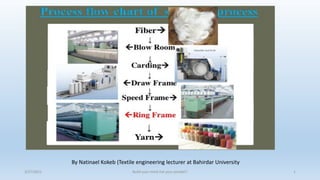
- 1. 3/27/2021 Build your mind not your pocket!! 1 By Natinael Kokeb (Textile engineering lecturer at Bahirdar University
- 2. 3/27/2021 Build your mind not your pocket!! 2
- 3. Roving frame
- 4. OBJECTIVES 1.To determines the type of motion transmission elements and its function 2. To analysis why these selected motion transmission elements are being used i.e. why we use other motion transmission elements rather the selected ones. 3. To analysis how builder motion occurs by using motion transmission elements in roving frame. 4. To determine the tasks of builder motion in roving frame. 5. To know to which parts are motion transmitted through proper selected motion transmission elements i.e.to analysis the effects when we use other than the selected motion transmission elements. 6. To know the effects of motion transmission elements in drafting arrangement; creel; bobbin rail; bobbin drive and spindles. 7. To analysis speed variations in bobbin drive; creel zone; and drafting rollers. 3/27/2021 Build your mind not your pocket!! 4
- 5. MAIN TASKS OF ROVING FRAME 1. Attenuation-drafting the sliver into roving. 2. Twisting the drafted strand. 3. Winding the twisted roving on bobbin. ➢ Advantages of roller chain drives; • Do not slip • Maintain constant and precise speed • Good service life • Easy to install and repair • Long distance motion transmission. ➢ Disadvantages of roller chain drives; • noisy • need lubrication • weight of the chain ❖ Since the V belt is short, it is subjected to the action of load and fatigue a greater number of times. Further, its ability in absorbing the shocks is poor. and the flat belt have the same application but the difference is we use flat belt on smooth pulley or cone and the other difference is the length they transfer power and the flat belt have slippage. 3/27/2021 Build your mind not your pocket!! 5
- 6. GEARS AND GEAR DRIVES A.Parallel 1.Spur gear 2.Helical gear 3.Rack and pinion B.Intersecting 1.Bevel gear C.Non-intersecting and Non-parallel 1.Worm Gears are generally used for one of four different reasons:- • To reverse the direction of rotation • To increase or decrease the speed of rotation • To move rotational motion to a different axis • To keep the rotation of two axis synchronized Bevel gear Spur gear 3/27/2021 Build your mind not your pocket!! 6
- 7. Ratchet change wheel This determines the amount by which the belt is shifted at each operation of the ratchet and therefore must be adjusted precisely to the increase in bobbin diameter. It used to control lifting of cone belt in cone drive to produce tapered end of roving package and doffing purpose when required length of roving length in bobbin. Generally; ratchet is used to 1. To form tapered end of package by shifting cone belt. 2. To shorten lifting distance after each layer. 3. To know how many numbers of layers wound in bobbin. ratchet wheel 3/27/2021 Build your mind not your pocket!! 7
- 8. 3/27/2021 Build your mind not your pocket!! 8 This continuously reducing rotation rate of bottom conedrum is transmitted via gearing to the differential and is there superimposed on the constant speed of the main shaft. During winding of the roving bobbin, the flyer rotation rate is normally held constant. Winding is effected only when the difference between the speeds of the flyer and bobbin is equal to the delivery speed. Differential gear
- 9. Materials Cradle length Cotton up to 1 1/ 8” Synthetic fibers 40mm 36mm Cotton above 1 1/ 8 Synthetics 50 mm 43mm Synthetics 60 mm 50 mm Spacers are used between top and bottom aprons to create space between them. The gap between the top and bottom aprons at the front end decides the pressure existed on the fibres and the fibre control. 3/27/2021 Build your mind not your pocket!! 9
- 10. 1 3/27/2021 Build your mind not your pocket!! 10
- 11. On the main shaft is mounted, another mechanism called, a ‘differential motion’. The function of the differential motion is to take drives from two different sources and give an output of a combined nature. (The input drive from one source (main motor) is superimposed on the input drive from the second (bottom conedrum) and an output, which is a combination of both source drives, is delivered). The differential motion will ‘add’ the speeds of the main shaft and that of the bottom cone drum output, so that the speed of the bobbin is always higher than the spindle speed. Further, if the drive from the bottom cone drum is cut off to the differential, the spindles and the bobbins will be rotating at the same speed. The output of the differential motion is used to drive the bobbins through a gear train, as indicated in the gearing diagram. 3/27/2021 Build your mind not your pocket!! 11
- 12. 3/27/2021 Build your mind not your pocket!! 12
- 13. 3/27/2021 Build your mind not your pocket!! 13
- 14. 3/27/2021 Build your mind not your pocket!! 14
- 15. 3/27/2021 Build your mind not your pocket!! 15
- 16. 3/27/2021 Build your mind not your pocket!! 16 Attenuation = Draft 100/ (100-P) where, P is the percentage waste. If there is wastage, then attenuation will be more than expected due to draft. So,
- 17. 3/27/2021 Build your mind not your pocket!! 17
- 18. ❖Axial flutes are now replaced by helical flutes for better grip of fibers and motion smoothness of top rollers. 3/27/2021 Build your mind not your pocket!! 18
- 19. 3/27/2021 Build your mind not your pocket!! 19 The ratio between the speeds of the delivery and feed of the drafting device is called “mechanical draft”.
- 20. 3/27/2021 Build your mind not your pocket!! 20
- 21. 3/27/2021 Build your mind not your pocket!! 21
- 22. size of condensers should be selected according to the volume of the fibre. 3/27/2021 Build your mind not your pocket!! 22
- 23. 3/27/2021 Build your mind not your pocket!! 23
- 24. Twist (tpm) decreases with increasing tex count according to t=k/texn where t is twist in turns/metre, k and n are constants. High twist level ----> Production loss .......................------> Drafting problem in ring Spinning. Low twist level -------> false drafts ....................................Roving break As the count increases, in order to hold the fibers, twist multiplier also increases, so that corresponding twist per inches also increases. 3/27/2021 Build your mind not your pocket!! 24
- 25. In most of the industries, top mounted flyer is used since it allows automation of the doffing operation. The flyer is supported at top and driven by gear wheel running by toothed belts. Closed flyers are mainly used for high speed operation. It also has advantages of reduced spreading of the legs at high operating speeds. 3/27/2021 Build your mind not your pocket!! 25
- 26. Flyer top ❖ The passage of roving at the entry point of the flyer determines the degree of twist and the winding tension. ❖ If the roving has only low twist or is coarse, so that there is a risk of false drafts the strand passes through the flyer top to the guide groove without wrapping (A). ❖ A half turn of wrap as shown in (B), is selected for high speed frames winding large packages with high twist levels. The wrap enables better control of roving tension and the package build becomes more even winding to the harder coils. 3/27/2021 Build your mind not your pocket!! 26
- 27. • The additional false twist reduces the roving break in the Spinning. • Spinning triangle is reduced so that quality of roving is improved. • Fly and lap formation also reduced. • False twist enables compact rovings which increases the bobbin capacity and leads to higher flyer speeds False twist 3/27/2021 Build your mind not your pocket!! 27
- 28. Bobbins placed in these front and back row spindles will the following differences in the spinning conditions following variations. • The angle of approach of the roving to the flyer top is different for the two rows. This will create different rolling conditions at the entry point of the roving to the flyer top. • Both rows of spindles will have different spinning triangles . • Difference in the unsupported lengths (L), i.e the lengths between the drafting arrangement and the flyer top. • Difference also occurs in twisting of roving which leads to variation in fineness between the front and rear ends. Disadvantage of arranging bobbins in two rows 3/27/2021 Build your mind not your pocket!! 28
- 29. • The pressure arm made up of steel yoke is attached to the lower end of the hollow flyer leg. • It guides the roving from exit of the flyer leg to the package. • The roving is wrapped two (A) or three (B) times around the yoke depending upon the fibre type and twist level. • No. of turns determines the roving tension and package hardness. • If this is high, then a hard, compact package is obtained. If it is too high, false drafts or roving breaks may happen. THE PRESSURE ARM 3/27/2021 Build your mind not your pocket!! 29
- 30. 3/27/2021 Build your mind not your pocket!! 30
- 31. 3/27/2021 Build your mind not your pocket!! 31
- 32. 3/27/2021 Build your mind not your pocket!! 32
- 33. 3/27/2021 Build your mind not your pocket!! 33 Advantages of leading bobbin are: 1.Fewer roving breaks or faultily drafted places at the winding point because the drive transmission path from the motor to the spindle is short, whereas that of the bobbin is long 2. No unwinding of the layers during roving breakage and 3. Speed reduction with increasing package diameter. However, with a leading spindle, the bobbin speed must be gradually increased with increasing package diameter which demands more power.
- 34. 3/27/2021 Build your mind not your pocket!! 34 ❖ Variation in bobbin speed originates from the cone drums. When the builder motion shifts the cone belt, the rotation rate of the lower cone is changed.
- 35. 3/27/2021 Build your mind not your pocket!! 35
- 36. 3/27/2021 Build your mind not your pocket!! 36
- 37. 3/27/2021 Build your mind not your pocket!! 37
- 38. Roving frame calculation Where TCP=twist change pinion
- 39. 1.Calculate the TPI on simplex if the diameter of back roller is 15/16”, rpm of B.R is 10, rpm of flyer is 1000 and draft is 6 Given: Db= 15/16 inch, rpm Br= 10, rpm flayer=1000, draft=6, TPI=? so/n: Draft=( ss Fr/ss Br), ss Br= Db*rpm Br=*(15/16)in*10=29.45in/min So, 6=ss Fr/29.45In/min, Ss Fr= 6*29.45In/min=176.71In/min Tpi= spindl rpm/Ss Fr =(1000 rpm/176.71In/min)=5.66 ans If twist constant is given as 520, what is the no. of teeth in the twist change pinion(TCP)? 3/27/2021 Build your mind not your pocket!! 39
- 40. • Coils per inch 3/27/2021 Build your mind not your pocket!! 40
- 41. Find out the total draft of m/c, draft of every zone. And the draft constant of m/c. radius of the 2nd roller 7/8’’ • Show that the draft in the front zone is 3. 3/27/2021 Build your mind not your pocket!! 41
- 42. Ring frame 3/27/2021 Build your mind not your pocket!! 42
- 43. 3/27/2021 Build your mind not your pocket!! 43
- 44. 3/27/2021 Build your mind not your pocket!! 44
- 45. 3/27/2021 Build your mind not your pocket!! 45
- 46. ❖ The roving bobbins (1) are creeled (A) in appropriate holders (3). Guide rails (4) lead the rovings (2) into the drafting arrangement (5) which attenuates them to the final required count. ❖ The drafting arrangement (B) is inclined at an angle of about 45 – 600. It is one of the most important assemblies on the machine since it has considerable influence on irregularities present in the yarn. ❖ After the drafting arrangement, the machine have twisting and winding zone (C). ❖ Upon leaving the front rollers, the emerging fine fiber strand (6) receives the twist needed to give it strength. This twist is generated by the spindle, which rotates at high speed. Each revolution of the spindle imparts one turn of twist to the fiber strand. Spinning of the yarn is thus complete. ❖ In order to wind up the twisted yarn to bobbin mounted on Spindle( 8) , a traveller (9) is required to cooperate with the spindle. The traveller moves on guide provided on the ring (10) encircling the spindle. ❖ The traveller has no direct drive; instead, it is carried along by the yarn it is threaded with. The speed of the traveller is lower than that of the spindle owing to significant friction generated between the traveller and ring. ❖ This difference in speed enables winding of the yarn to bobbin. ❖ Winding of the yarn on to the bobbin is done by raising and lowering the ring rail. The traverse stroke of the ring rail is less than that of the bobbin height. The ring rail must therefore be raised by small amount after each layer of coils. Principles of operation 3/27/2021 Build your mind not your pocket!! 46
- 47. Advantage of ring spinning over new spinning technologies: ➢ It is universally applicable, most of the textile fibres can be spun to required fineness. ➢ The yarn spun from this machine demonstrate excellent quality features like uniform structure and good strength. ➢ It is easy to operate as compared to other spinning machines. ➢ The “know-how” for operation of the machine is well established. ➢ It is flexible as regard to quantities in terms of blend and lot sizes. 3/27/2021 Build your mind not your pocket!! 47
- 48. Disadvantages associated with ring spinning are: ➢ More process stages. Roving stage exists as an extra process compared to the other systems. ➢ Yarn breakages are more frequent as a result of ring traveller friction and yarn to air drag forces. Interruptions, broken ends and piecing up problems exist because of the yarn breakages. ➢ The high speed of the traveller damages the fibers. ➢ The capacity of the cops is limited. ➢ Energy cost is very high. ➢ Low production rate. 3/27/2021 Build your mind not your pocket!! 48
- 49. 3/27/2021 Build your mind not your pocket!! 49
- 50. 3/27/2021 Build your mind not your pocket!! 50
- 51. The distance between the central axes of two pairs of rollers is called as roller setting. If the pairs of rollers are set too wide apart, there will be plucking of the fibres instead of even attenuation, and the material that comes forward is full of thick and thin portions. On the other hand, if they are set too close, drafting becomes difficult and many of the long fibres get gripped by both the pairs momentarily. The fibres get either damaged or broken. Assignment:- discuss on what types of rings with travelers are suitable for manmade and synthetic fibers? And discuss on traveler number used for polyster, viscous and coton spinning? Anti-wedge rings with spin or clip type of travelers are most suitable for man-made fibre processing. The cross section of the travelers should be half round. Travelers for polyester blends have to be about 4-5 numbers heavier and those for viscose, 3-4 numbers heavier as compared to travelers used for 100% cotton yarns. 3/27/2021 Build your mind not your pocket!! 51
- 52. hardness of top roller ➢ Soft - 60° to 70° shore ➢ Medium - 70° to 90° shore ➢ Hard – above 90° sore ❖ What will happen if drafting roller hardness is very low? Covering having hardness less than 60° shore is normally unsuitable because they cannot recover from the deformation caused by squeezing out on each revolution of the roller. Also they wear out at the faster rate. Why traveler clearer is used? Due to deposition and entangling of flying loose fibres and untwisted fibres on traveler, mass of traveler is increased that result in increased yarn tension which finally induce an end break. 3/27/2021 Build your mind not your pocket!! 52
- 53. 3/27/2021 Build your mind not your pocket!! 53
- 54. 3/27/2021 Build your mind not your pocket!! 54 A good ring should have the following features: 1. Best quality raw material 2. Good, but not too high, surface smoothness 3. An even surface 4. Exact roundness 5. Good, even surface hardness which is higher than that of the traveller 6. Optimal running-in conditions 7. Long operating lifetime 8. Correct relationship between ring and cop tube diameters ) 1 : 2 . 2 1 . 2 ( 2 . 2 2 upto Coptube Ring − = 9) Correct relationship between ring diameter and tube height 10) Horizontal disposition 11) It should be exactly centered relative to the spindle − = 225 . 0 2 . 0 Tubeheight Ring
- 55. 3/27/2021 Build your mind not your pocket!! 55
- 56. 3/27/2021 Build your mind not your pocket!! 56
- 57. 3/27/2021 Build your mind not your pocket!! 57
- 58. Main and cross layers 3/27/2021 Build your mind not your pocket!! 58
- 59. 3/27/2021 Build your mind not your pocket!! 59
- 60. Spinning Geometry • On its path from roving bobbin to cop, the fiber strand passes through the drafting arrangement, thread guide, balloon control ring and traveller • These parts are arranged at various angles and distances relative to one another which give varying deflections and paths of travel for the yarn. • The set of dimensions and different angles are called spinning geometry which has a significant influence on the spinning operation and the resulting yarn, primarily upon:
- 61. 1. Tension conditions 4.inding-in of the fibers 2. Number of end breaks 5.Yarn hairiness 3. Yarn irregularity 6.Generation of fly • The turns of twist in a yarn are generated at the traveler and travel against the direction of yarn movement to the drafting arrangement • Twist must run back as close as possible to the nip line of the rollers, but it never penetrates completely to the nip because after leaving the rollers, the fibers first have to be diverted inwards and wrapped around each other
- 62. • Accordingly, at the exit from the rollers, there is always a triangular bundle of fibers without twist which is called spinning triangle Most end breaks originate at this weak point because the yarn tension in the balloon can be transmitted almost without hindrance as far as the drafting arrangement whereas twist in the spinning triangle is zero and does not attain its full value in the adjoining yarn section because of friction at the thread guide.
- 63. • A short spinning triangle represented a small weak point and hence few end breaks. • However, if the spinning triangle is too short, the fibers on the edge must be strongly deflected to bind them in • A long spinning triangle implies a long weak point, and hence more end breaks. But the edge fibers are better bound into the yarn which gives a smoother yarn and less fly. • Low inclination of the drafting arrangement with respect to the horizontal results in a large angle of deflection. This will give a long spinning triangle. However, steeper inclination results in small angle of deflection and hence short spinning triangle.
- 64. 3/27/2021 Build your mind not your pocket!! 64
- 65. Ring calculation • Winding speed = VSpdl - VT • But winding speed = L • Therefore, L = VSpdl - VT • = dnspdl - dnT • = d( nspdl – nT) • => 3/27/2021 Build your mind not your pocket!! 65 d L n n spdl T − =
- 66. The length of one winding coil is dw, therefore the length of the yarn wound every minute is L= (ns-nt) dw Where ns-nt are the number of yarn coils wound in one minute, ns is the r.p.m. of the spindle, nt is the r.p.m. of the traveller, dw is the diameter of winding. • The length of the yarn wound onto the bobbin in one minute is equal to: L = Vf.r. Kc = df.r.nf.r.Kc
- 67. Where vf.r. = L1 is the length of the strand delivered by the front roll per minute Kc is the contraction coefficient. Then the formula for yarn winding is as follows: (ns-nt)dw = vf.r.kc And • which means that the travelers' lagging behind depends on the speed of yarn delivery and on the winding diameter. w c r f s t d K v n n . . − =
- 68. Let spindle speed be 13, 500rpm, front roller delivery 15m/min, and layer diameters at tip and base 25mm and 46mm respectively. *Traveller speed at the base, nTB, is: nTB= 13, 5000 - 15, 000 = 13, 500 - 104 = 13,396rpm 46 *Traveller speed at the tip, nTT is: nTT =13,500 - 15,000 = 13,500-191 = 13,309rpm 25 Using spindle speed, Twist/m =13,500/15 = 900.00 Using traveller speeds, Twist/m at the base = 13,396/15 = 893.07 Twist/m at the tip = 13,309/15 = 887.27
- 69. Rotor spinning Card sliver 3/27/2021 Build your mind not your pocket!! 69
- 70. Tasks of rotor spinning machine 1. Opening almost to individual fibers (fiber separation) 2. Cleaning 3. Homogenizing through back-doubling to improve evenness 4. Combining (forming a coherent linear strand from individual fibers) 5. Ordering (the fibers in the strand must have an orientation as far as possible in the longitudinal direction) 6. Imparting strength by twisting and 7. Winding to a cylindrical (weaving) or conical (knitting) cross-wound packages
- 71. Spinning Conditions 1--Rotor speed was 46,400 r.p.m. 2--Opening roll speed was 6,200 r.p.m. 3--Opening roll type was OK 40 4--Rotor diameter was 54 mm 5--Navel type used was: a--smooth for maximum strength at high twist b--grooved for spinnability at low twist Rotor spinning 3/27/2021 Build your mind not your pocket!! 71
- 72. 3/27/2021 Build your mind not your pocket!! 72
- 73. 3/27/2021 Build your mind not your pocket!! 73
- 74. 3/27/2021 Build your mind not your pocket!! 74
- 75. 3/27/2021 Build your mind not your pocket!! 75
- 76. Rotor Diameter D Current minimum: 28 mm Minimum D > Staple Length Must have sufficient size so that longest fibre does not form a complete loop Smaller rotor higher speed ➢ Opening Roller Speed Higher speed gives better fibre opening. Optimum depends on fiber, yarn and rotor speed. If opening roller speed is too high, fibre striping by air may not be complete, leading to more yarn faults. 3/27/2021 Build your mind not your pocket!! 76
- 77. Nozzle 3/27/2021 Build your mind not your pocket!! 77
- 78. Piecing: • Feed the yarn from the package into the spinning box (up to the nozzle) • Start fiber feeding • Bring the yarn to the rotor groove • The fibers in the rotor groove connect to the yarn end • Start draw off the yarn (spinning process is started) • Process fully performed & controlled by the robot Fault: Moiré effect • Caused by trash particle sticking in the rotor groove • As a result: Periodic yarn fault (“MO-Fault”) • Yarn cleaner can detect MO-Fault and stop the process • Rotor cleaning needed to remove the trash 3/27/2021 Build your mind not your pocket!! 78
- 79. Fiber separation and fiber flow: • The opening roller opens the sliver to single fibers • Trash particles fall out through the trash window • The fibers are transported with air through the fiber channel into the rotor. BYpass: Allows settings for the trash removal: • BYpass open: highest trash extraction (fine yarns, e.g. Ne 30) • BYpass half open: medium trash extraction (medium and coarse yarns, e.g. Ne 10 denim) • BYpass closed: lowest trash extraction (spinning of man made fibers) 3/27/2021 Build your mind not your pocket!! 79
- 80. 3/27/2021 Build your mind not your pocket!! 80
- 81. 3/27/2021 Build your mind not your pocket!! 81
- 82. Factors Affecting Rotor Spinning of Fine Cotton Yarns 1) Raw Materials and Their Properties 2) Preparation for Spinning 3) Sliver Weight and Spinning Draft 4) Yarn Count Range 5) Yarn Twist 6) Yarn Properties a) Yarn Appearance b) End Breakage in Spinning c) Yarn Evenness d) Yarn Tenacity 3/27/2021 Build your mind not your pocket!! 82
- 83. Back doubling = Rotational speed of rotor/Lead of the yarn at the separation point D = Rotor diameter; t/m = twist per metre Steel novels are used for synthetic fibers of rotor spinning, Because at higher speeds, steel novel has the advantage of better heat conduction and hence less heating of the fibres, so that fibre damage can be avoided. Evenness of rotor yarn is increased by means of back doubling. 3/27/2021 Build your mind not your pocket!! 83
- 84. • The point at which the ribbon is pulled from the rotor groove is called the peel-off point, P • Since the ribbon is pulled at the delivery roller speed, Vd, the peel-off point circulates the circumference of the rotor at a rotational speed of Vd /πDR, where DR is the rotor diameter • This means that, relative to the doffing tube, the peel-off point rotates faster than the rotor such that NP = NR + Vd /πDR
- 85. limitations of rotor yarn a. Strength of yarn is less due to less migration of fibres b. Finer count is not possible merits of rotor yarn over ring spun yarn a. Fibres are compactly oriented. b. More abrasive strength c. Production speed is 200 m/min whereas ring spinning production speed is 20 m/min d. More uniformity of yarn e. Hairiness is less f. Elimination of cop to cone winding, i.e Direct package is obtained g. Elimination of conversion of sliver to roving 3/27/2021 Build your mind not your pocket!! 85
- 86. rotor yarn is weaker on average than ring yarn but, being more even, has better appearance and is relatively free of weak spots that may cause yarn breaks in later processes. Features of Rotor Spinning ❖ Yarn properties: lower tensile strength than ring yarns; good uniformity and cleanliness. ❖ Application: for woven, warp knit and knitted materials. ❖ Advantages: low manufacturing cost; fully automated. ❖ Limitations: not the same range of application possibilities as ring-yarns. 3/27/2021 Build your mind not your pocket!! 86
- 87. 3/27/2021 Build your mind not your pocket!! 87
- 88. 3/27/2021 Build your mind not your pocket!! 88
- 89. 3/27/2021 Build your mind not your pocket!! 89
- 90. 3/27/2021 Build your mind not your pocket!! 90
- 91. 3/27/2021 Build your mind not your pocket!! 91
- 92. 3/27/2021 Build your mind not your pocket!! 92