
Recommended
More Related Content
What's hot
What's hot (20)
Similar to Reciprocating Internal Combustion Engine
Similar to Reciprocating Internal Combustion Engine (20)
Recently uploaded
Recently uploaded (20)
Reciprocating Internal Combustion Engine
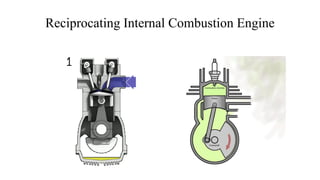
- 1. Reciprocating Internal Combustion Engine
- 2. Heat engine: A heat engine is a device which transforms the chemical energy of a fuel into thermal energy and uses this energy to produce mechanical work.
- 3. IC engine Classification…….. a) Type of the fuel used as : (1) Petrol engine (2) Diesel engine (3) Gas engine (4) Bi-fuel engine (Two fuel engine) b) Nature of thermodynamic cycle as : (1) Otto cycle engine (2) Diesel cycle engine (3) Duel or mixed cycle engine c) Number of strokes per cycle as : (1) Four stroke engine (2) Two stroke engine d) Method of ignition as : (1) Spark ignition engine (S.I. engine) Mixture of air and fuel is ignited by electric spark. (2) Compression ignition engine (C.I. engine) e) Method of cooling as : (1) Air cooled engine (2) Water cooled engine f) Speed of the engine as : (1) Low speed (2) Medium speed (3) High speed g) Number of cylinder as : (1) Single cylinder engine (2) Multi cylinder engine h) Position of the cylinder as : (1) Inline engines (2) V – engines (3) Radial engines (4) Opposed cylinder engine (5) X – Type engine (6) H – Type Engine (7)U – Type Engine (8) Opposed piston engine (9) Delta Type Engine
- 4. Main components of reciprocating IC engines: Cylinder: It is the main part of the engine inside which piston reciprocates to and fro. It should have high strength to withstand high pressure above 50 bar and temperature above 2000 oC. The ordinary engine is made of cast iron and heavy duty engines are made of steel alloys or aluminum alloys. In the multi-cylinder engine, the cylinders are cast in one block known as cylinder block. Cylinder head: The top end of the cylinder is covered by cylinder head over which inlet and exhaust valve, spark plug or injectors are mounted. A copper or asbestos gasket is provided between the engine cylinder and cylinder head to make an air tight joint. Piston: Transmit the force exerted by the burning of charge to the connecting rod. Usually made of aluminum alloy which has good heat conducting property and greater strength at higher temperature.
- 5. Piston rings: These are housed in the circumferential grooves provided on the outer surface of the piston and made of steel alloys which retain elastic properties even at high temperature. 2 types of rings- compression and oil rings. Compression ring is upper ring of the piston which provides air tight seal to prevent leakage of the burnt gases into the lower portion. Oil ring is lower ring which provides effective seal to prevent leakage of the oil into the engine cylinder. Connecting rod: It converts reciprocating motion of the piston into circular motion of the crank shaft, in the working stroke. The smaller end of the connecting rod is connected with the piston by gudgeon pin and bigger end of the connecting rod is connected with the crank with crank pin. The special steel alloys or aluminum alloys are used for the manufacture of connecting rod. Crankshaft: It converts the reciprocating motion of the piston into the rotary motion with the help of connecting rod. The special steel alloys are used for the manufacturing of the crankshaft. It consists of eccentric portion called crank. Crank case: It houses cylinder and crankshaft of the IC engine and also serves as sump for the lubricating oil. Flywheel: It is big wheel mounted on the crankshaft, whose function is to maintain its speed constant. It is done by storing excess energy during the power stroke, which is returned during other stroke.
- 6. Terminology used in IC engine: 1. Cylinder bore (D): The nominal inner diameter of the working cylinder. 2. Piston area (A): The area of circle of diameter equal to the cylinder bore. 3. Stroke (L): The nominal distance through which a working piston moves between two successive reversals of its direction of motion. 4. Dead centre: The position of the working piston and the moving parts which are mechanically connected to it at the moment when the direction of the piston motion is reversed (at either end point of the stroke). (a) Bottom dead centre (BDC): Dead centre when the piston is nearest to the crankshaft. (b) Top dead centre (TDC): Dead centre when the position is farthest from the crankshaft. 5. Displacement volume or swept volume (Vs): The nominal volume generated by the working piston when travelling from the one dead centre to next one and given as, Vs=A × L 6. Clearance volume (Vc): the nominal volume of the space on the combustion side of the piston at the top dead centre. 7. Cylinder volume (V): Total volume of the cylinder. V= Vs + Vc 8. Compression ratio (r): Vs/Vc
- 7. Four stroke engine: Cycle of operation completed in four strokes of the piston or two revolution of the piston. (i) Suction stroke (suction valve open, exhaust valve closed)-charge consisting of fresh air mixed with the fuel is drawn into the cylinder due to the vacuum pressure created by the movement of the piston from TDC to BDC. (ii) Compression stroke (both valves closed)-fresh charge is compressed into clearance volume by the return stroke of the piston and ignited by the spark for combustion. Hence pressure and temperature is increased due to the combustion of fuel. (iii) Expansion stroke (both valves closed)-high pressure of the burnt gases force the piston towards BDC and hence power is obtained at the crankshaft. (iv) Exhaust stroke (exhaust valve open, suction valve closed)- burned gases expel out due to the movement of piston from BDC to TDC.
- 8. Two stroke engine: -No piston stroke for suction and exhaust operations -Suction is accomplished by air compressed in crankcase or by a blower -Induction of compressed air removes the products of combustion through exhaust ports -Transfer port is there to supply the fresh charge into combustion chamber
- 9. Air Standard Cycles In most of the power developing systems, such as petrol engine, diesel engine and gas turbine, the common working fluid used is air. These devices take in either a mixture of fuel and air as in petrol engine or air and fuel separately and mix them in the combustion chamber as in diesel engine The mass of fuel used compared with the mass of air is rather small. Therefore the properties of mixture can be approximated to the properties of air. Exact condition existing within the actual engine cylinder are very difficult to determine, but by making certain simplifying assumptions, it is possible to approximate these conditions more or less closely. The approximate engine cycles thus analyzed are known as theoretical cycles. The simplest theoretical cycle is called the air-cycle approximation. The air-cycle approximation used for calculating conditions in internal combustion engine is called the air-standard cycle.
- 10. The analysis of all air-standard cycles is based upon the following assumption: a) The gas in the engine cylinder is a perfect gas, i.e. it obeys the gas laws and has constant specific heats. b) The physical constants of the gas in the cylinder are the same as those of air at moderate temperatures i.e., Cp = 1.005 kJ/kg K and Cv = 0.718 kJ/kg K. c) The compression and expansion processes are adiabatic and they take place without internal friction, i.e., these processes are isentropic. d) No chemical reaction takes place in the cylinder. Heat is supplied or rejected by bringing a hot body or a cold body in contact with cylinder at appropriate points during the process. Because of many simplifying assumptions, it is clear that the air-cycle approximation does not closely represent the conditions within the actual cylinder. Due to the simplicity of the air-cycle calculation, it is often used to obtain approximate answers to complex engine problems.
- 11. Auto or constant volume cycle
- 17. Difference between Air standard cycle and Actual cycle: Air standard cycle Actual cycle Air is working fluid. A mixture of air and fuel is a working fluid. Air behaves as the ideal gas. Working fluid does not always behave like an ideal gas. Specific heat of air is constant. Specific heats are variable with respect to temperature. No internal heat generation. Generation of energy by burning of fuel with air. No frictional losses. Frictional losses are present. This cycle is completely closed. Because of the inlet and exhaust process, the cycle is not
- 18. Losses in Actual Cycle • Losses due to variation of specific heats with temperature:. • Time losses, effect of spark timing • Incomplete combustion loss. • Direct heat loss. • Exhaust blow down loss. • Pumping losses. • Friction losses.
- 19. Four-stroke Actual Cycle For Spark Ignition Engine • P-V Diagram for 4 Stroke S.I Engine: Induction Stroke 1-2: Piston moves from TDC to BDC, creates negative pressure in cylinder Due to Pressure Difference, air rushes to cylinder through carburetor where fuel mixed with air in specific amount, filling the cylinder Compression Stroke2-3: Valves are closed and piston moves from BDC to TDC At “S” point spark produces but combustion is delayed From “S” to “3” volume being constant, and combustion occurs Working Stroke 3-4: As a result of combustion, pressurized gas starts expanding to give work to piston Exhaust valves are opened to discharge combustion products at point “E” Exhaust Stroke 4-1: From 4-1 the pressure is slightly higher than atmospheric pressure. All combustion gas products discharge however the exhaust in clearance volume remains trap. P-V Diagram for SI Engine
- 20. • IO (Inlet valve Open) the actual position is between 100 before TDC and 150 after TDC • IC (Inlet valve Closed) This occurs 20o-40o after BDC to take advantage of the momentum of the rapidly moving gases • S (Spark occurs) this is 20o-40o before TDC when the ignition is fully advanced and is at TDC when the ignition is fully retarded • EO (Exhaust valve opens) the average value of this position is about 50o before BDC. • EC (Exhaust valve closes) this occurs 0o to 10o after TDC It should be noted that crank angle displacements can be translated into time values if the engine rotational speed is known and can be assumed to be constant. Timing Diagram of SI 4 stroke Engine Timing Diagram for SI Petrol Engine: Specifies the timing diagram of SI Engine, having two revolution of the crankshaft as shown with reference to TDC and BDC.
- 21. Two Stroke Cycle • 2 Stroke Petrol Engine Cycle: Fig represents the cylinder of 2 stroke petrol engine in which we have the following working cycle: • Working: As the piston moves to TDC the “S” spring-loaded valve Begins open, the air fuel mixture drawn into crankcase C Ignition occurs as a result working stroke occurs As the piston start downward motion about 80%, the E Port opens and exhaust begin Soon as the exhaust discharges from the cylinder at the Same time the T port opens, and the charges rushes to cylinder. This process is known as Scavenging. 2 stroke petrol engine
- 22. • Pressure-Volume Diagram for 2 Stroke For Petrol (SI) Engine: Fig part-a represent the P-V cycle diagram for both cylinder and the crankcase. • Timing Diagram : Specific angular position : I (Inlet angle) approx. 800 E (Exhaust angle) approx. 1200 T (Transfer angle) approx. 1000 Timing Diagram P-V Diagram