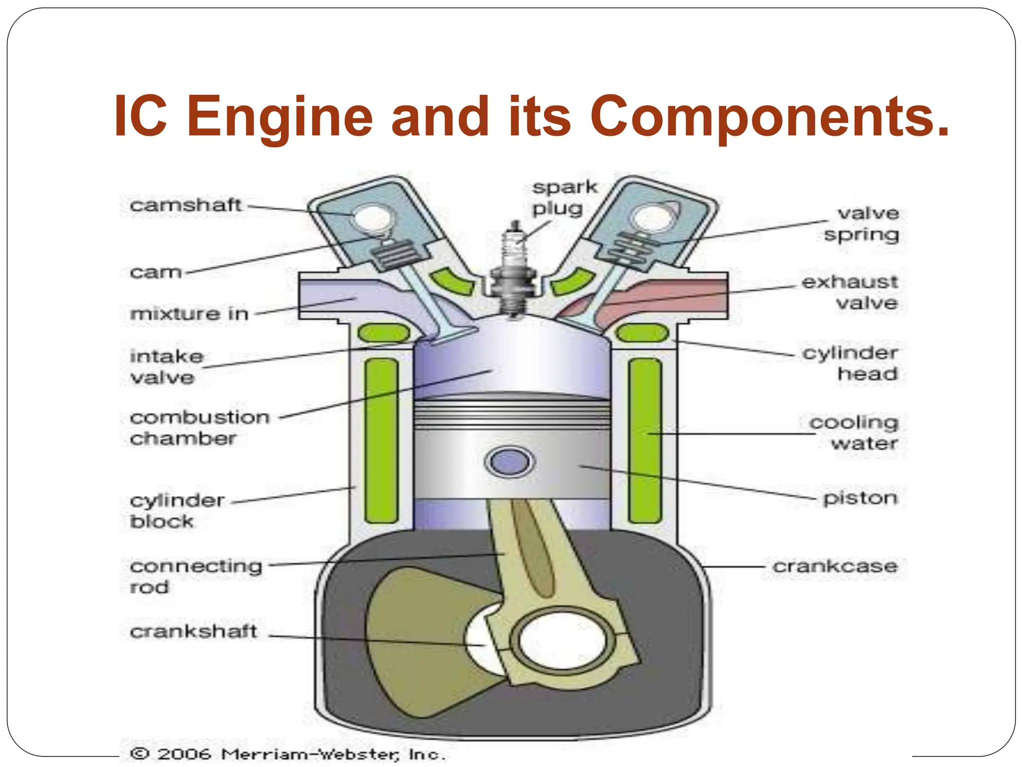
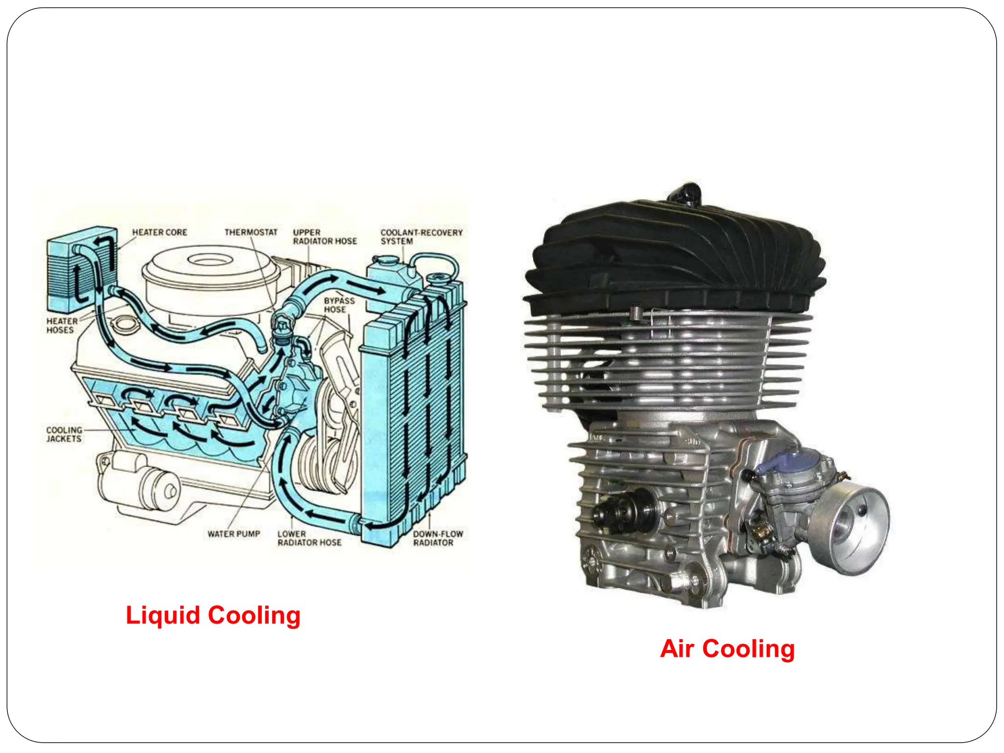
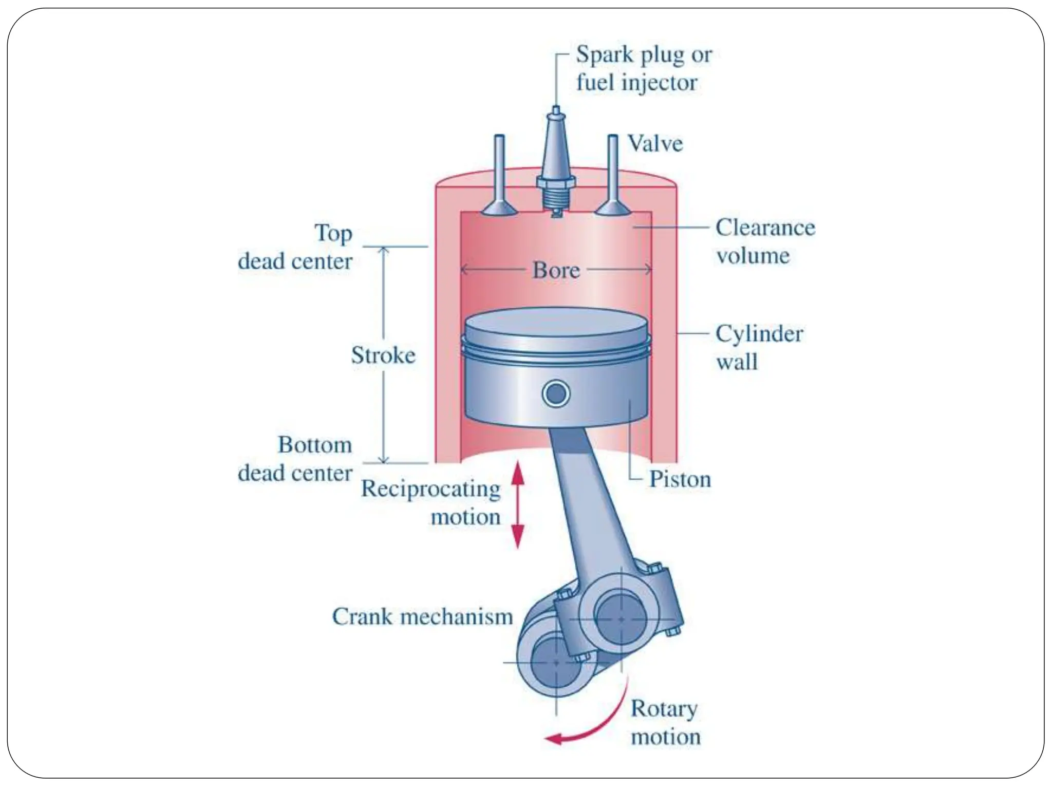
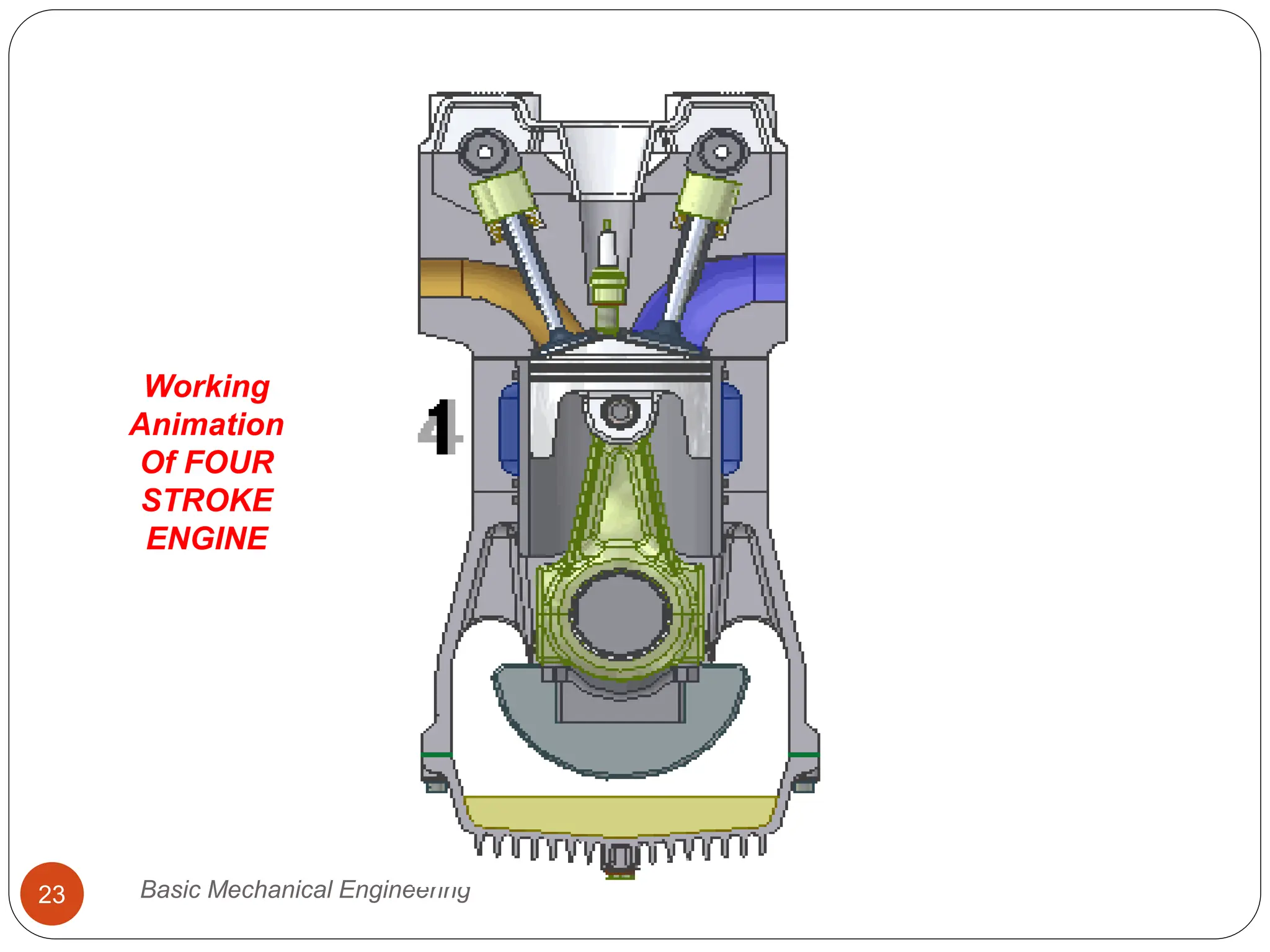
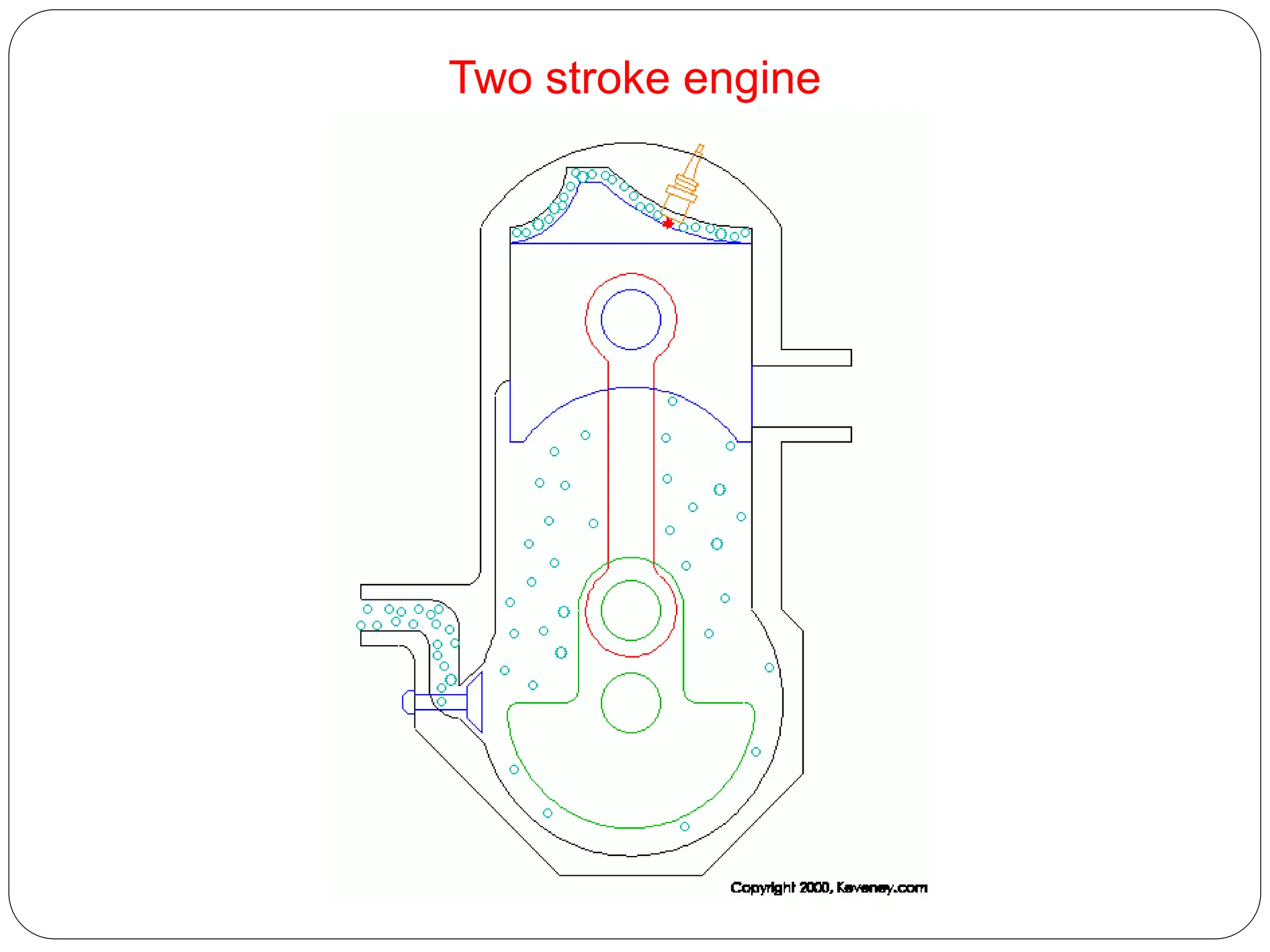
3. 1. Cylinder:
Piston Reciprocates to develop power.
Pressure 70 bar & Temperature 2200°C
Material- Cast Iron & for heavy duty alloy steel.
2. Cylinder Head:
Closes one end of the cylinder. It is bolted to top of the
cylinder. Copper and asbestos gaskets are provide
between
the cylinder and cylinder head to obtain gas tight joint.
Material- Cast Iron.
4. 3. Piston and Piston Ring:
To compress the charge during compression stroke
and
transmit gas force to the connecting rod and then
to the crank
during power stroke.
Material – CI, Cast Steel and aluminum alloy.
Housed in the circumferential grooves provided
on the outer surface of the piston. It gives gas
fitting between the piston and cylinder & prevents
leakage of HP gases. The upper rings are called
the compression rings and lower piston rings are
5. 4. Connecting Rod.
Small end joined to the piston
and big end is connected to
the crank by crank pin.
6. 5. Crank and Crank Shaft
Rotating shaft through which engine work output is
supplied to external systems. The crankshaft is
connected to the engine block with the main
bearings.It is rotated by the reciprocating pistons
through the connecting rods connected to the
crankshaft
7. 6. Inlet Valve
7. Exhaust Valve
8. Valve Spring: The valves are kept closed by the
valve spring.
9. Inlet Manifold : Passage which carries the
charge from carburetor the petrol engine.
10.Exhaust Manifold :Passage which carries the
exhaust gases from the exhaust valve to the
atmosphere.
12. S.No Engine Parts Material Used Method of
Manufacturing
1 Cylinder CI, alloy Steel Casting
2 Cylinder Head CI, Aluminium alloy Casting, Forging
3 Piston CI, Aluminium alloy Casting
4 Piston Ring Silicon cast iron Casting
5 Gudgeon pin Steel Forging
6 Valves Special Steel alloy Forging
7 Connecting Rod Steel Forging
8 Crank Shaft Alloy Steel Forging
9 Crank Case Cast iron, steel Casting
10 Bearings White metal, lead bronze Casting
13. Engine Classification:
1 .Type Of Ignition:
S I
C I
2. Engine Cycle :
Four Stroke
Two Stroke
3. Valve Location :
Valve in head called I head engine.
Valve in block also called L head engine.
14.
15. 4. Basic Design :
Reciprocating Engine
a. Single Cylinder
b. Multi Cylinder - In-line
V
Radial
Opposed Cylinder
Opposed Piston
Rotary Engine - (a) Single Rotor
(b) Multi-rotor
24. Two-stroke cycle
Gas exchange occurs between the working cycles by scavenging the exhaust
gases with a fresh cylinder charge
Control mostly via intake end exhaust ports
In contrast to the four-stroke cycle , no valve train is necessary, but a blower is
need for scavenging air
Two-stroke cycle
29. Assumptions of Air Standard
Cycle
The working medium is assumed to be a perfect
gas.
All the process that constitute the cycle is
reversible.
Heat is assumed to be supplied from a constant
high temperature source and not from chemical
reaction during the cycle.
Some heat is assumed to be rejected to constant
low temp. sink during the cycle.
The cycle is considered to be closed, with the
same air always remaining in the system to
repeat the cycle.
31. Process 1 2 Isentropic compression
Process 2 3 Constant volume heat addition
Process 3 4 Isentropic expansion
Process 4 1 Constant volume heat rejection
v2
TC
TC
v1
BC BC
Qout
Qin
Air-Standard Otto cycle
3
4
2
1
v
v
v
v
r
Compression ratio:
37. Fuel Air Cycles
Air Standard cycle gives estimate of engine
performance which is much greater than actual
performance.
The variation is due to non instantaneous burning
and valve operation and incomplete combustion.
In actual engine the working fluid is not air but
mixture of air and exhaust gases.
The specific heat are not constant but increases
with rise in temp.
38.
39. Actual Cycle
Suction process is possible when pressure in the
cylinder is below atmospheric pressure to admit
the mixture.
The exhaust is above atm pressure
The compression process and expansion process
are polytropic due to heat transfer between the
system and surrounding.
Combustion process is carried out by providing a
spark to mixture few degree before TDC. The
pressure rise takes place through some crank
rotation.
Exhaust at point 4 is not instantaneous sine there
is a time gap in opening the exhaust valve.
40. Effect of Various Factors
1. Effect of Composition of Fuel and Air (A/F Ratio):
• Leaner mixture has higher thermal efficiency
• Richer mixture will have lower efficiency as unburnt
fuel will go to exhaust
• Efficiency increases with CR
1
1
1
1
1
1
1
1
r
OR
r
diesel
otto
41. 2. Dissociation
Disintegration of combustion product at high
temp.
Heat is absorbed & heat will be liberated when
the
elements recombine as the temp. falls.
Reverse of combustion process.
Effect of dissociation much smaller than that
change of specific heat.
Dissociation lowers the temp & consequently the
press. at the beginning of the stroke. This causes
loss of power and efficiency.