SlideShare a Scribd company logo
1 of 28
Download to read offline
25 13EPTEE028
CHAPTER 4
WINDING OF TRANSFORMER
The conducting material used for the windings depends upon the application, but in all
cases the individual turns must be electrically insulated from each other to ensure that the
current travels throughout every turn. For small power and signal transformers, in which
currents are low and the potential difference between adjacent turns is small, the coils are
often wound from enamelled magnet wire, such as Formvar wire. Larger power
transformers operating at high voltages may be wound with copper rectangular strip
conductors insulated by oil-impregnated paper and blocks of pressboard.
Figure4.1:-paper insulation
Cut view through transformer windings. White: insulator. Green spiral: Grain oriented
silicon steel. Black: Primary winding made of oxygen-free copper. Red: Secondary
winding. Top left: Toroidal transformer. Right: C-core, but E-core would be similar. The
black windings are made of film. Top: Equally low capacitance between all ends of both
windings. Since most cores are at least moderately conductive they also need insulation.
Bottom: Lowest capacitance for one end of the secondary winding needed for low-power
high-voltage transformers. Bottom left: Reduction of leakage inductance would lead to
increase of capacitance.
26 13EPTEE028
High-frequency transformers operating in the tens to hundreds of kilohertz often have
windings made of braided Litz wire to minimize the skin-effect and proximity effect
losses. Large power transformers use multiple-stranded conductors as well, since even at
low power frequencies non-uniform distribution of current would otherwise exist in high-
current windings. Each strand is individually insulated, and the strands are arranged so
that at certain points in the winding, or throughout the whole winding, each portion
occupies different relative positions in the complete conductor. The transposition
equalizes the current flowing in each strand of the conductor, and reduces eddy current
losses in the winding itself. The stranded conductor is also more flexible than a solid
conductor of similar size, aiding manufacture.
The windings of signal transformers minimize leakage inductance and stray capacitance
to improve high-frequency response. Coils are split into sections, and those sections
interleaved between the sections of the other winding.
Power-frequency transformers may have taps at intermediate points on the winding,
usually on the higher voltage winding side, for voltage adjustment. Taps may be
manually reconnected, or a manual or automatic switch may be provided for changing
taps. Automatic on-load tap changers are used in electric power transmission or
distribution, on equipment such as arc furnace transformers, or for automatic voltage
regulators for sensitive loads. Audio-frequency transformers, used for the distribution of
audio to public address loudspeakers, have taps to allow adjustment of impedance to each
speaker. A center-tapped transformer is often used in the output stage of an audio power
amplifier in a push-pull circuit. Modulation transformers in AM transmitters are very
similar.
Dry-type transformer winding insulation systems can be either of standard open-wound
'dip-and-bake' construction or of higher quality designs that include vacuum pressure
impregnation (VPI), vacuum pressure encapsulation (VPE), and cast coil encapsulation
processes. In the VPI process, a combination of heat, vacuum and pressure is used to
thoroughly seal, bind, and eliminate entrained air voids in the winding polyester resin
insulation coat layer, thus increasing resistance to corona. VPE windings are similar to
27 13EPTEE028
VPI windings but provide more protection against environmental effects, such as from
water, dirt or corrosive ambients, by multiple dips including typically in terms of final
epoxy coat.
4.1 Practical Transformer Winding:-
Figure 4.1. practical transformer winding
In the good old times it was a matter of fact that every electronic hobbyist or technician
would wind himself any power transformers he needed, and rewind any that burned out.
Unfortunately, nowadays transformer winding is fast becoming a lost art, and I have seen
many people despair about where to find some very specific transformer, or pull their
hair out about the cost of having one professionally wound to specifications.
Since I started in electronics, as a 12 year old boy, I have always wound my own
transformers. I started using the basic, but useful instructions provided in The Radio
Amateur's Handbook of the time, and later I came to better understand how transformers
work, which enabled me to optimize a given transformer for the intended application.
Following a request by many readers of my web site, I've added this page, which is
complementary to the previously published Transformers and coils. You should first read
28 13EPTEE028
(and understand!) that page, before trying to design any transformer. Then come to this
more practically-oriented page, to learn some tricks and hints about the design process,
and about hands-on winding.
This page addresses mainly single-phase power transformers in the power range from
about 1 watt to 10,000 watts, operating at line frequencies, but much of what's described
here can be applied to a wide range of other transformers too.
Figure 4.2 transformer LV winding
Let's start with the materials. To make a typical transformer, you need the iron
laminations for the core, enameled copper wire of several different diameters for the
windings, a bobbin (or some material to make one), insulating material to apply between
wire layers, between windings, around the whole winding assembly, and on exposed
wires, and in most cases it's also a good idea to use an impregnation varnish.
The photo here shows several stacks of iron E-I laminations, two coils of wire (with
cardboard protecting the wire from damage), one roll of thick, stiff Pressspan, another
roll of NMN laminate (we will soon see what that is), two small bundles of spaghetti for
wire protection, and a can of transformer varnish. Add to this some glue, cotton straps,
ropes, adhesive tape, terminals, bolts, angle iron, and other small material, and that's it.
29 13EPTEE028
4.1.2 Low voltage winding
All these materials are sold by companies specializing in transformers and parts for
transformers. Enameled wire is also sold by many other distributors, but is usually
cheapest at the places that sell it together with the other materials. You will have to dig
into the phone book or some other directory to find these companies, since they don't
usually have a shiny nice store in the downtown shopping mall!
Transformer iron is an alloy of iron with silicon and some other minor components. It's
characterized by a relatively high permeability, very high saturation flux density,
relatively low hysteresis loss, and relatively high specific resistance. This latter factor,
along with the practice of using the material in thin, insulated sheets, reduces the power
losses produced by eddy currents.
Figure 4.3. transformer assembling
The most common shape of these sheets is shown at right. It's the classic "economy E-I"
shape. Why it's called E-I should be pretty obvious when looking at the photo! But the
explanation for "economy" might be a bit more elusive: It's because at the exact
proportions shown in the photo, the I's are nothing else than the cutouts to make the
windows in the E's, when two E's are cut facing each other! This allows stamping E's and
30 13EPTEE028
I's out of a large steel sheet, without any wasting of material, except for the little round
bits cut out of the bolt holes. By the way, small laminations often don't have such bolt
holes, and such cores are held together by clamps instead of bolts, or even welded.
The lamination in the photo is a large one, as the comparison with my hand shows. It's an
E80 (the center leg is 80mm wide), typically used for transformers in the 3 to 10 kilowatt
range!
In any E-I lamination you are likely to encounter, the center leg is twice as wide as each
of the other parts. This is because the entire magnetic flux has to go through the center
leg, but then splits up, with one half of the flux returning through each of the side legs. If
you ever come across a lamination that has all three legs of the same width, then you are
looking at a lamination intended for three phase transformers!
Such an economy E-I lamination like shown here has completely fixed proportions,
beyond the rule above, that stem from the need to cut the I out of the winding window of
two E's facing each other: If the center leg is 2 units wide, then the window is 1 x 3 units,
the total E is 6 x 4 units, the I is 1 x 6 units, and so on.
Not all laminations follow the "economy" proportions, though. Here is an example of a
lamination that comes in one piece, instead of being divided into an E and an I, and that
has the windows proportionally much larger than the E-I lamination shown above. Such a
lamination is a bit more expensive to make, because the steel cut from the windows
is wasted, unless the manufacturer can find some other use for it. But being able to
accomodate a much large winding assembly, it has some advantages in certain cases.
These "non-economy" laminations were quite usual in Europe, many years ago, but
nowadays copper is so much more expensive than steel, that transformers are usually
designed to use more steel and less copper. And for that goal, the economy lamination is
very well suited.
31 13EPTEE028
The laminations should be thin, and reasonably well insulated from each other, to reduce
eddy currents to an insignificant value. Typical thicknesses vary from 0.2 to 0.5mm, but
higher frequency transformers (audio) use much thinner ones, while extremely large
transformers might use slightly thicker ones.
The insulation is often applied at the factory that makes the big rolls of steel sheet, even
before stamping the E's and I's. Different kinds of insulation are used: A thin oxide layer,
a thin layer of enamel, or any of several chemical processes. Antique transformers
sometimes even used very thin paper!
When I was young, patient and overly eager to do things right, I painted each and every E
and I for my transformers, using diluted transformer varnish, to make a thin, nice layer.
The photo shows the steel for a 200 watt transformer, drying. Later, getting old and lazy,
I noticed that the layer of rust on old, recycled laminations is more than enough
insulation, and that the very thin and imperfect insulation that comes on new laminations
is enough too, even if it takes only a light scratch with the multimeter's test probe to
puncture it and get through to the steel. We don't need perfect insulation between the
sheets! We only need enough resistance to reduce eddy currents to a low level.
Transformer steel is not all born alike. Manufacturers will provide data sheets about their
products (often on their web sites), where you can see what they offer. There are usually
many grades, with vastly different loss characteristics. At a given flux density and
frequency, a good material might have ten times less loss than a cheap material! So it
pays to look, investigate, and decide intelligently what to buy. Thinner sheets normally
have lower loss, and the rest of the secret lies in the exact alloy. In any case, you need to
know what material you have, to be able to make a meaningful transformer design!
Some transformer steel is grain-oriented. That means that when rolling the steel sheets, a
process is used to align the crystalline grains in the direction of the rolling. This kind of
material has particularly good behavior when the magnetic flux is aligned with the
direction in which the sheet was rolled, but is worse than standard material in the
perpendicular direction. Such grain-oriented material is ideal for toroidal cores, which are
32 13EPTEE028
made by coiling up a long strip of steel, but is not a large improvement for E-I
laminations, because in these a significant portion of the material has to work with the
flux perpendicular to the rolling direction.
Enamelled copper wire comes in many different diameters, and with several different
kinds of enamel. The diameters vary from less than that of a hair, to about that of a child's
finger. Different standards exist for the wire diameter. A very common one is American
Wire Gauge, shortened to AWG, which is used in much of the world. Britain has its own
standard, and in many countries the wire is specified simply by its diameter in
millimeters.
Thick wires usually are coated with a sort of enamel that is very tough, an excellent
insulator, highly heat-resistant, highly resistant to solvents, and that clings to copper even
better than dirt does to children! This enamel is usually yellowish clear, so that the wire
coated in it looks mostly copper-colored, but many exceptions exist. To solder the ends of
these wires, it's necessary to scrape off the enamel, using a sharp knife or similar
tool. This procedure would be too difficult with a thin, fragile wire, so that these thin
wires are instead covered with an enamel that has most of the same characteristics of the
other one, except the heat resistance: It will melt and turn into solder flux at a
temperature a common soldering iron easily achieves!
. .
Figure 4.4 low winding manufacturing
33 13EPTEE028
This allows easily soldering these wires, without previously stripping them. But
transformers using this latter kind of wire enamel cannot survive temperatures as high as
those using only the former kind of wire enamel. The red wire on the right side in this
photo has this kind of enamel. But be careful with colors! The clear wire on the extreme
left side also has solderable enamel, while the dark violet one in the middle is of the non-
melting variety!
The thickness of the enamel layer depends on the wire thickness, the manufacturer, and
can sometimes be chosen: Some manufacturers will offer the wire with seeral different
thicknesses of enamel. In any case, the diameter specified by a certain AWG number
refers to the copper diameter, so that the complete wire, with enamel, will be slightly
thicker than what the AWG standard tells!
Figure4.5. Low voltage side winding
Here is a wire table for AWG wire. It shows the AWG number, the diameter in
millimeters excluding the enamel, the approximate typical total diameter including the
enamel (but this varies somewhat), the cross sectional copper area in square millimeters,
the area of the square of window space occupied by that wire in a transformer (including
the enamel, of course), the current carrying capacity at a typical, average value of current
34 13EPTEE028
density, the resistance in ohms per meter, and finally how many meters of that wire come
in one kilogram, because enamelled wire is usually bought by weight, not length.
This table has wires from AWG #1 to #40, and for the thickest ones I didn't calculate all
data. But you should be aware that there are wires exceeding this range! The thinnest I
have ever used was #46. It breaks when you blow at it! The photo here shows a #39 wire
lying on a #7 wire. The hairy thing below is my floor carpet. Note that even this #39 wire
is not much thicker than the hairs of this carpet!
It's interesting to note that every three AWG numbers, the cross sectional area exactly
doubles. Any deviation from this in my table is due to approximation errors.Modern
transformers of small to moderate size are usually wound on plastic bobbins. Here you
can see simple ones. Some bobbins have pins or terminals molded into them, others have
one or two divisions. Some don't have the slits for terminals, which the ones shown here
do have
4.1.2 High voltage winding
Figure 4.6 High voltage winding transformer
35 13EPTEE028
Typically for a given size of E-I laminations, bobbins will be available in two or three
sizes, accomodating different numbers of steel sheets. So you can vary the amount of
steel in your transformer not only by choosing the lamination size, but also the height of
the lamination stack!
Here is a little transformer using a divided (or split) bobbin. This is very practical,
because it completely separates the primary from the secondary winding, making it much
easier to achieve the degree of insulation required for safety. More about that later.
If you cannot find a plastic bobbin in the proper size, don't despair! Bobbins can be easily
made from materials such as strong cardboard, or Pressspan, which is nothing else than a
particularly strong cardboard.
The bobbin shown here was made from 1.5mm thick Pressspan, which is really too thick
for this small bobbin, but I had nothing better on hand. The pieces are cut to size using a
sharp knife (X-acto or the like), and glued together with cyanoacrylate adhesive (instant
bonder). The clever structural design of this super high tech bobbin holds it together
perfectly while the glue sets!
You must make the inner dimensions of the bobbin core a tad larger than the transformer
center leg, but JUST a tad, no more, unless you want to waste valuable winding space!
The sides can be made pretty tight to the size of the laminations, because if they don't fit
at the end, they are easily enough cut or filed down, even after the winding has been
made. But the length of the bobbin must be smaller than the window length of the core,
by as much as 2 or 3%, plus any tolerances of your manufacture! Because it is critically
important that the E's and I's can touch each other properly, without being kept separated
by a bobbin that deformed during winding, and grew!
Be sure to at least break the corners as shown here, or even better, round them off.
Otherwise the wire is guaranteed to tangle at the sharp corners during winding, and a wire
loop sticking out of the completed winding can ruin the whole thing!
36 13EPTEE028
Note that the junction of the bobbin's center piece is placed in the middle of one side,
and not in a corner. It's next to impossible to produce a reasonably symmetrical and
precise bobbin when placing the junction in a corner.
If the material is thin compared to the bobbin size, the junction should be made by
overlapping the material. Of course, the overlapped junction is always placed on one side
that will end up outside the core window, so that the added bulk has little detrimental
effect.
To bend this thick material in reasonably clean right angles, my technique is to use a
sharp knife to cut out a 90 degree wedge from the inside, along each bend line, leaving
only the outer third of the material intact. After that admittedly cruel treatment,
Most antique transformers, and many of the larger modern ones, don't use a real complete
bobbin. Instead, they use only the center former, and no sides at all! It takes some tricks
and practice to wind a transformer like this without having the whole thing come apart
many times over during winding, but for people who have acquired enough practice, it's
faster than making a real bobbin! Further down, I will show you a trick to make this kind
of transformer, with high quality.
Note in this photo how the Argentinian maker of this transformer (back in 1931!) used
insulating material of several different thicknesses for the bobbin center, the interlayer
insulation, the interwinding insulation, and the terminal support.
You might ask why any insulation material is required at all, if the wire is insulated by its
enamel layer! Well, the enamel is very thin, and easily scratched. It might survive as
much as a few thousand volts, but it might also break down with a lot less! It depends on
type, condition, thickness, temperature, and other factors. So, wherever the voltage can
exceed a few tens of volts, some additional insulation needs to be used. Specially
between the primary and secondary, safety regulations ask for an insulation good for at
least 4000 volts, to avoid electrocuting somebody when there is a lightning transient on
the AC power network.
37 13EPTEE028
In antique transformers, the most usual insulating material was paper, impregnated with
something like beeswax, tar or the like. This impregnation had several purposes: Mainly,
it would seal the pores of the paper, making it a really good insulator, while without the
impregnation it would only insulate as well as the same thickness of air! But in addition,
it kept moisture out, it helped stick the thin wires in place during winding, and it
improved the thermal conductivity of the completed winding assembly.
Modern insulating materials are far superior. Plastic sheets such as Mylar provide
excellent dielectric strength and have no pores, so they require no impregnation to realize
their high degree of insulation. Nomex instead, with its fibrous structure, behaves like
paper, but both Nomex and Mylar are much better than paper at surviving high
temperatures! This is a key characteristic of insulating materials: The temperature class.
It's coded with a letter. Paper would have an A or B rating, telling that it is fine for
temperatures not much above that of boiling water. Different plastic insulation materials
instead are routinely available in classes as high as F, G or even H! They can safely run
much hotter than paper can.
The photo shows an NMN insulating sheet. This is a sandwich of a Mylar sheet
embedded between two layers of Nomex. The Nomex will eagerly soak up and distribute
the impregnation varnish (or the oil, in an oil-inmersed transformer), while the Mylar will
provide safe insulation even in places that for any reason stayed dry! I love this material.
It's thermal class G, if I remember right.
Insulation materials come not only in many different variants, and temperature classes,
but of course also in many different thicknesses. You choose the proper thickness so that
it has enough dielectric strength and mechanical strength, without taking up an undue
portion of your valuable window space!
Despite all modern materials, good old paper and cardboard is still used sometimes.
Mostly in its form known by the German word Pressspan, which means "compressed
chips", and is simply a very dense paper or cardboard.
38 13EPTEE028
It's very good practice to soak a completed transformer in some impregnation varnish. It
will form fillets around wires, papers, and anything else. It will improve the insulation,
make the transformer highly moisture-proof, glue everything together so that nothing can
rattle, come loose, or chafe through, it will improve thermal transfer, and so on.
Varnish comes in several thermal classes, just like the insulation material, and also it
comes in variants that dry at high temperature, or at room temperature. My experience is
that no varnish ever fully dries at room temperature, and when you start using the
transformer and it warms up, the varnish inside will start drying, and stink! So, it's
necessary to apply heat anyway, regardless of what sort of varnish you use.
Now that you have turned into a person very knowledgeable about transformer materials,
let's turn to those pesky questions such as "how many turns do I have to wind?" or "what
wire size?" or "how much power will I get?"
There are three typical situations:
1 You need to repair/rewind a transformer that burned out.
2 Your want to rewind an existing transformer, to produce the voltages and currents
you need, which are different from the original ones. A variation of this case is
when you want a certain voltage, at the highest current that transformer can
provide.
3 You have fixed specifications, want to design a transformer to optimally meet
them, and you will buy the core and all other materials.
Let's start with the first case. You MUST find out why that transformer failed! A
correctly designed, correctly built and correctly used transformer is, for all
practical ends, eternal. If it failed, there is a reason. If you know that the
transformer was shorted, overloaded for a long while, exposed to intense lightning
transients, thrown into water, gnawed through by rats, exposed to corrosive
substances, or anything like that, then your best approach is to unwind it, count
the turns, measure the wire sizes, and rewind it exactly as it was originally
made.The photo shows an antique speaker field coil, mounted in my winding
39 13EPTEE028
machine. I unwind coils by pulling off the wire while having the thing spin in the
machine, so that the turns counter in the machine will do the pesky job of keeping
count. The problem, as illustrated here, is often that thin wires won't come off
nicely! They are stuck in place, and will break, then entire chunks of wire will
come off all together. This often makes it hard to accurately count the turns.
In such cases you might simply estimate how many turns you didn't count. Or you can
collect all the pieces of wire you removed, weigh them, calculate the amount of wire
from there, and calculate the turns number from it. Or, instead of unwinding the coil, cut
it with a knife or better a Dremel tool, remove it in one block, measure the cross sectional
area of the entire winding, then remove a little piece of wire to measure the diameter, and
finally calculate the number of turns from this. Any of these methods will usually be
precise enough for non-demanding applications, and none of it will be precise enough
when you need anything critical.
By the way, do you know how to precisely measure the diameter of a thin wire, when you
don't have a micrometer screw? Simple: You wind 10 or 20 or even more turns tightly on
a former (such as a screwdriver stem), measure the length of the coil with a common
ruler, then divide by the number of turns to get the wire diameter. It's highly accurate.
Sometimes it's even better than using a micrometer screw, which can flatten the wire if
you apply too much torque!
But there are cases when you have a burned transformer, and no good reason why it
burned. It might have been a manufacturing defect, a huge transient, an overload that
went undetected, but maybe - the Gods of Electromagnetics forbid - that transformer
might have been misdesigned! In that case, painstakingly rewinding it with the same wire
gauges and turn numbers as original, will only produce a transformer that will fail again.
So, if you don't know why a transformer failed, re-do the design, and compare your
results with what the manufacturer did! Many manufacturers are cheapskates, and use
substandard transformers, in the hope that most clients will never use them intensively
enough to blow them up! This sends you straight to the section about the third case,
further down this page!
40 13EPTEE028
In the second case, when you want to rewind an existing transformer for new output
values, very often the transformer will already have a properly wound and healthy
primary winding. In such a case, keep it! There is no point in unwinding and rewinding
the primary, if it is fine. The calculation work for such a transformer is quite simple:
Before taking it apart, measure the voltage delivered by the secondary. Disassemble it,
unwind the secondary, counting the turns, and calculate the number of turns per volt from
this. Calculate the new number of turns you need for your desired voltage. Calculate
what's the largest wire size that will comfortably fit in the available space. Get the wire,
wind it, and assemble the transformer. The power rating will be the same as before, and
this allows you to calculate the current you can safely draw, at your new voltage.
Do you know what you can do with all that wire you remove from old transformers?
Well, a super trendy wig, like the one shown here, modelled by my sister, is sure to catch
everybody's attention! Otherwise, there isn't really much use for such wire. It comes out
totally kinked, stretched, broken, scraped, with varnish, wax or tar sticking to it. Don't
even dream about ever re-using it in any other transformer!
power capability, with a reasonably simple, but nonlinear curve. This curve also depends
on the quality of the core material, and several other factors.
The next step is calculating how many turns per volt you need on this core. To this end,
you have to decide how much flux density you will put through your core, and then you
can apply the equations from Transformers and coils. The optimal flux density might be
anything from 0.8 to 1.6 Tesla, and sometimes even outside this range! General rules of
thumb are these:
 Larger transformers use lower flux densities.
 Better core material uses higher flux densities.
 Transformers that are always energized, but rarely used at full power, use lower
flux densities.
 Likewise, transformers that work at full power whenever energized, use very high
flux density.
41 13EPTEE028
 Forced air cooled transformers use higher flux density.
 Oil-immersed transformers use even higher flux density!
 Higher flux density produces better voltage regulation.
 Lower flux density produces less base loss.
 Lower flux density is less likely to produce humming noise, and magnetic stray
fields.
 Lower flux density produces lower iron loss, but higher copper loss.
I have seen many text books giving design equations that result in a flux density of 1
Tesla in each and every transformer you calculate by them, like if that were a sacred rule!
If you come across any such book, BURN IT! It's nonsense! While 1 Tesla indeed tends
to produce a workable transformer in most cases, in at least 70% of all situations it's far
enough from the optimal value to warrant some effort toward optimization! Specially in
small transformers, and in those using the better core materials.
So, I suggest to start with a value chosen from the rules above, and then calculate the
transformer based on this value, analyzing the losses, heating, voltage drop, efficiency,
and so on. Then change the flux density, by 10 or 20%, and re-do all the calculations.
You will see what I mean! There is a clear optimum value for flux density in each
particular case, and this value is very often sufficiently removed from 1 Tesla to make
you wonder why some book authors still copy that "magic number" from other, long
gone authors! Most likely they have no idea about the matter they are copying.
That said, sometimes I do wind my transformers for 1 Tesla, because there are cases
when this is really a good value!
The loss calculation isn't very hard: The manufacturers of transformer steel specify the
loss of their products, as a certain amount of watts per unit of volume or weight, under
certain conditions of frequency and flux density. And the better of these data sheets also
contain curves, or give equations, to calculate the loss under different conditions. That's
about the iron loss. The total loss of the transformer also includes the copper loss,
42 13EPTEE028
Figure4.7 first turn of transformer lv winding
In this sheet, you enter your data in the green area, and watch what happens in the orange
one. The first three values you have to enter are the ones that specify the core. First is the
center leg width of the lamination used, in millimeters. The 100mm width given in the
example is a pretty large lamination. You will typically use values between 12 and
50mm. The sheet is based on the proportions of the economy E-I core, so that you don't
need to enter any other dimensions of the lamination. If you happen to be using
a lamination that has different proportions than the economy E-I, you should still enter
the width of the center leg, but later you will need to manually compensate for the larger
available window, by increasing wire size beyond that calculated by the sheet, reducing
the copper loss, and so on.
The second value you have to enter about the core is the stack height, also expressed in
millimeters. This is simply the height of the stack of E's, well compressed. This sheet
does not allow you to enter the stacking factor, which tells how much of the stack is
actually steel. There's always some little space used by insulation, and even wasted space
due to imperfect compression. But the effect of this is small enough to ignore, as long as
you compress the stack well enough!
43 13EPTEE028
Good stack heights to use are from the same as the center leg width, to close to twice that.
Often you have the choice to use a certain lamination, stacked as high as the center leg is
wide, or use the next smaller lamination, stacked much higher, with both options
producing the same output. It pays to simulate both options, optimize each, and compare
the efficiency, voltage drop, weight, and cost! The differences can be profound.
And the third value is the loss factor of the steel material. This must be taken from the
datasheet provided by the manufacturer of the lamination. My sheet expects this loss
factor to be expressed in watts per kilogram of material, at a flux density of 1 tesla and a
frequency of 50 hertz. Many data sheets include the value in this exact form, but those
published by US companies might instead express the loss factor in an eclectic mixture of
metric, CGS and Imperial units! If that's what you have, you will need to convert the
value into its fully metric equivalent. You might want to modify the spreadsheet to do
that.
The value of 2 W/kg @ 1T and 50Hz is pretty representative for modern low cost
laminations. A modern ultra low loss material might be a lot better, while an antique or
ultra-cheap material might be significantly worse.
The next three values in that column are pretty obvious: You have to indicate the primary
and secondary voltages, and the frequency of operation. The secondary voltage refers to
the open circuit (no load) voltage. And the frequency will usually be either 50 or 60
Hertz. If you enter a frequency far away from this, it's quite possible that the loss
calculated for the material will be rather imprecise, so use this sheet with caution if you
need to design a transformer for a very different frequency.
In the right hand column, you have four values which are design decisions which you can
vary somewhat. The first is the all-important flux density. Just try varying that value, and
watch how things change in the orange output area! Specially, see what happens with the
iron loss. I have already given guidelines about what flux density to use. Use them and
see what happens in your case, when you change it.
44 13EPTEE028
The next is the amount of copper cross section you will allow for each ampere of current
in the windings. Reasonable values are about 0.25 mm^2/A for very small transformers,
increasing to 0.5 for large ones. 0.35 is typical for medium sized transformers (50 to 300
watts or so). When you adjust this value, the design of the transformer doesn't really
change, but the sheet will calculate a new set of currents, power, voltage drop, efficiency
and loss. With this parameter, you basically are telling the sheet how much you will
stress a particular transformer.
The fill factor expresses how much of the lamination's window will actually be filled
with copper. It can never be very high, because a lot of that area gets inevitably filled out
with the bobbin, the wire's lacquer, the air around the round wire, the insulation between
layers, between windings, and some space is always lost due to sloppy winding, even if
you are careful! The value of 0.4 used in this example has proven in practice to be
achievable without much trouble. If you wind very carefully, and minimize the amount of
space devoted to insulation, you should be able to get up to 0.5. But don't push this
number too much, or you will end up with a transformer design that you cannot actually
wind! On the contrary, if you have never before wound a transformer, and will do so by
hand, in a ragged, ugly winding, it might be a good idea to design the transformer with an
even lower fill factor, such as 0.3, to make sure you will be able to fit all the turns! Of
course, using a lower fill factor means simply using thinner wire, and this means that at a
given amount of loss and heating, you get less current.
The fill factor can be pushed beyond 0.5 when you wind a transformer with square wire
(instead of round), or with copper tape separated by thin layers of insulation. But square
wire is hard to find and a hassle to wind properly, and tape winding is acceptably easy
only for transformers that have rather few turns. This is often the case with high
frequency transformers used in switching power supplies, but not at line frequencies.
The temperature rise defines how many Kelvins (same as degrees Celsius in this case)
hotter than the surrounding air and objects you want your transformer to run. You need to
carefully choose this value, according to the highest ambient temperature (inside the
equipment!) at which your transformer will have to work, also taking into account the
45 13EPTEE028
highest temperature your wire, insulation material, varnish, glue, etc, can survive. And
what's most difficult, you will also need to estimate the thermal gradient from the
innermost wire turns (the hottest ones) to the transformer's surface! Calculating all this
can be quite hard, and I can't give you simplified equations for it. Maybe you can find
them elsewhere. The value of 70 Kelvins which I used in the example design is relatively
high. This is so because this transformer would work in open air, not inside a housing,
where the ambient temperature is never above 25 degrees Celsius; also, I used class G
or higher insulating material, wire and varnish throughout; and finally, this transformer
was carefully impregnated with varnish, giving it a reasonably good thermal conductivity
between winding layers.
If your transformer will not be impregnated, or use class A or B insulation material
(paper), or run inside a cabinet that can be hot, then you will need to use a lower value for
allowed temperature rise then my 70 Kelvins!
Finally, you can enter your local and current prices for enameled copper wire and
transformer steel laminations, to have the sheet calculate the cost of these main materials
for your transformer. All the additional cost, for the bobbin, insulation material,
terminals, bolts and so on, is usually small compared to the copper and steel cost. The
most expensive item is usually the wire, by far.
The first two lines of the orange output area of my spreadsheet show some basic results
for that transformer: The cross sectional area of the magnetic core and of the winding
window, also the total copper area (after applying the fill factor), the turns per volt
constant that will be valid for all windings on this transformer, and the average length of
one turn, which is calculated as the average between the length of a wire that goes around
the center leg touching it, and one that goes around the entire winding package, touching
the outer legs.
Then you have a line for the primary winding and one for the secondary. Each of these
lines tells you the number of turns, the length of the wire need to wind it, the copper cross
sectional area of the wire, and the nominal current that will flow at full rating. The
46 13EPTEE028
number of turns isn't rounded off, so you will have to do that, because you can't wind a
fraction of a turn. You can fiddle with your voltage data to get the sheet to show round
numbers of turns. The wire length is based on the length of the average turn, so this will
be correct only if you wind the primary and secondary side-by-side, on a split bobbin. If
instead you wind the secondary on top of the primary, you will need less wire than
calculated for the primary, and more than calculated for the secondary. Anyway, these
lengths are not very useful in practice, because wire is bought by weight, not length. The
main situation where they are useful is when you have to wind a transformer with several
thin wires in parallel, because these are much easier to bend than one thick wire. In such
a situation, it's great to know how long the total winding is, so that you can cut the
strands and twist them together, before you start winding.
The remainder of the orange output area is divided into two columns. The left one shows
some important performance data of the transformer: There is the input power, expressed
in voltamperes, which is really more correct than watts. The value calculated by the sheet
does not include the magnetizing current; calculating it would need additional
information about the core. But in medium to larger transformers, at least, the
magnetizing current tends to be small enough to be ignored.
Then comes the percentual power loss of the transformer, at full load. This includes both
the iron loss and copper loss. The output power is of course the input power minus this
loss.
Then we can see the voltage drop at full load. The value is calculated only from the
resistances of the windings. Any additional loss caused by imperfect coupling between
the windings is not considered here. So, if you use a poor core or winding technique, that
results in bad coupling, you should expect a somewhat higher voltage drop. Just for user
convenience, the sheet also calculates the output voltage under full load, which is based
on the voltage drop calculated above.
Below comes the weight of iron laminations and copper wire used in the transformer.
This has several purposes. One is knowing how heavy the beast will be, of course. The
47 13EPTEE028
other is knowing how much material you have to buy! If you use side-by-side winding of
the primary and secondary, you need to buy one half the calculated copper wire of each
size (plus some extra, of course, to be on the safe side). If instead you wind the secondary
over the primary, you need a little less than half of that weight of the primary wire, and a
little more than half that weight of the secondary.
And then, the sheet will calculate the total cost for laminations and wire, and also divide
this by the power, to give the cost per watt for your transformer, which is a good figure of
merit which you might want to optimize. Even while this calculation doesn't include the
cost for insulating material and other odds and ends, it's still a good reference.
The right side column of this area is about thermal matters. These tell whether your
transformer will survive, so don't take them lightly! The sheet calculates the power loss
in the iron, in the copper, and adds them to get the total power loss. Copper loss is
calculated at ambient temperature, though. When the wire heats up, its resistance
increases, and so its loss increases too! For this reason, take the calculated value with a
small grain of salt. The same is true for the voltage drop end efficiency calculations!
You need to be aware of the fact that the iron loss is essentially constant, regardless of the
load placed on the transformer, except for a little effect caused by voltage drop in the
windings reducing available magnetizing voltage, which causes a slight decrease in core
loss when the load gets higher ! The loss in the wire instead increases with the square of
the current taken from the transformer, and the value calculated by the sheet is for the full
rated current.
This gives you some big help in optimizing a transformer design. For example, a
transformer that will spend lots of time plugged in, but idling or loafing along at low
load, will see very little copper loss, but the iron loss will be there all the time. So, you
should design that transformer with a relatively low flux density, resulting in low core
loss, accepting a higher copper loss instead, by setting a smaller value of copper cross
section per ampere. After all, most of the time the rated design current won't be present,
so that the very high copper loss resulting in the calculation will be present only very
48 13EPTEE028
rarely, for short times! Transformers used in radio communication equipment, in audio
amplifiers, and many other uses, are best designed in this way.
The opposite case happens with transformers that are energized only briefly, but run at
full output power whenever energized. Examples of such use are microwave ovens and
spot welders. In such a transformer, iron loss always happens at the same time as copper
loss, and you can optimize the transformer to get the lowest total loss, regardless of how
it distributes between the iron and the copper. Even more, you might intentionally place
more loss into the core than the windings, based on the fact that the core is less prone to
be damaged by heat, has more thermal mass, and that the short operation time won't
allow the peak heat to distribute through the transformer! And then, such a transformer
that operates only for short times can be designed to have a really huge loss, because it
will have time to cool off between uses! These things are what makes microwave oven
transformers that deliver 800 watts be as small as a 200 watt transformer intended for
continuous service at low rate, and run at a flux density of 2 teslas or even more!
The heat produced by a transformer has to be dissipated to the surrounding air. The
spreadsheet calculates the approximate total surface area of the transformer, and finally
calculates a required thermal transfer coefficient, which expresses how much power the
transformer needs to dissipate per unit of surface it has, and per temperature rise allowed.
This coefficient tells you how difficult it will be to keep this transformer cool enough to
survive! The violet area below this coefficient includes referential values (not calculated
by the sheet) which you can use to try judging whether your transformer will be OK,
when you have it in a tight area, in a more open area, cooled by a fan, or immersed in oil.
I have my doubts about these values, specially aout the value for the oil-
immersed transformer, so please take these with a big grain of salt, and let me know if
you have any further, better, or more reliable data.
Anyway, my transformers designed for a coefficient of around 12 have all survived so
far, even while getting quite hot at full load, so this value can't be too far from the truth.
49 13EPTEE028
A typical design sequence using this spreadsheet would be to first enter the tentative core
size and loss, the required voltages and frequency, then start with something like 1 tesla
and 0.35mm^2/A, leaving the fill factor at 0.4 and setting the temperature rise according
to your transformer's materials and environment. Then you can observe the power and
current it would operate at, and the losses, efficiency, voltage drop, and also you would
get the thermal transfer coefficient which you can compare to the table to gain an idea of
whether the transformer will survive. You can then tweak the flux density and current
density, trying to get the characteristics into the range you need, without exceeding the
thermal possibilities. If you just can't find a combination that provides what you need,
you will have to try with a larger (or lower loss) core. Then you might want to explore
several different core sizes, optimizing each, and watch the cost, finally settling for the
design that best provides what you need, at the lowest possible cost, while staying in the
survivable thermal range.
This work with the spreadsheet is only the first step, though. When you have arrived at a
good design using the sheet, you need to tweak it to make it buildable with real, available
material! For example, you cannot get wire in any desired diameter. The sheet doesn't
know that; It might ask you for a wire measuring 1.2345 square millimeters, or anything
else. It's your job to see what wire you can actually buy, or maybe what wire you happen
to have in stock, and adapt the design. The AWG standard is quite finely stepped, so you
don't need to change the design very much to adapt it to standard AWG sizes. But I have
heard that in the US many stores only sell the even numbered AWG sizes of wire! That's
odd (pardon the pun), since even down here in less developed Chile I can easily buy all
AWG sizes, even and odd. If you are limited to even sizes only, you will have to make
bigger compromises.
A good approximation technique is to round the wire size to the nearest AWG size, or if
the values calculated fall just in the middle between AWG sizes, you might want to use
the next thicker wire for the primary, and the next smaller wire for the secondary. That
way the final losses and the amount of space required will be almost exactly the same as
calculated by the sheet.
50 13EPTEE028
If your transformer uses lots of turns of thin wire, you are about ready to start winding at
this point. But if it uses a winding that has few turns of a thick wire, you should check
how well (or how poorly) that wire fits in an integer number of layers, considering the
width of the bobbin, and about 5% of lost space due to the wire not being perfectly
straight. The problem is this: If the sheet calculates you need 48 turns of a certain wire
size, and it happens that you can fit only 15 turns per layer, then you will end up with
three complete layers, plus one additional layer in which you have just three turns! So the
total height taken up in the window by those 48 turns will be as much as 4 complete
layers, that could have 60 turns! Consequently, the winding might end up too high, and
won't fit the window! Then you cannot assemble the core, and you have to unwind that
winding, throw the wire away, get new (thinner) wire, do it again... you get the idea. Try
to avoid such frustration!
When you are in the situation just described, it would be wise to try the next smaller wire
size. It's very likely that this smaller wire size would accomodate 16 turns per layer, thus
allowing you to wind the 48 turns in three nice, clean, complete layers, and using up a
little bit less space than calculated by the sheet. This can in turn allow you to use the next
larger wire size for the other winding, which will almost completely compensate for the
higher loss and voltage drop of the smaller wire you used for the 48 turns!
Putting it in short words, you have to pick the best wire sizes for your transformer so that
their cross sections are close enough to the calculated values, but still allow a good,
space-saving distribution on the bobbin and thus inside the window area of the core.
Sometimes you might end up with a high current transformer requiring a very thick wire.
Such a wire is very stiff! If the bobbin is small, you might not be able to bend that thick
wire tightly enough around the corners of the bobbin. The result would be a huge loss of
space, and the completed winding wouldn't fit in the window, making it unusable. To
work around this problem, you can replace one thick wire by a bundle of seven wires,
each of which is one third as thick as the single wire. Such a seven wire bundle twists
very nicely into a round cable, and is more then 20 times as flexible as the single thick
wire! It costs only very slightly more money, and performs great. So, this is the way to go
51 13EPTEE028
when you have a need for such thick high current conductors. It's good to know that an
AWG number 10 units higher is roughly one third the diameter. So, if you would need a
#7 wire and this is too thick to wind comfortably, you can use 7 strands of #17, lightly
twisted together.
Sometimes instead of using one thick wire you will also find it convenient to wind with
two or three thinner wires in parallel, without twisting them. This technique can
significantly ease the distribution of a winding in entire layers.
Another hint: Most transformers use some thin and some thick wire. For transformers that
have the windings on top of each other (instead of side-by-side), I suggest to always first
wind the windings that use the thin wire, then the ones using thicker wires, regardless of
which will be primary and secondary. This allows to wind the stiffer wire on the outside,
where the bending radius required is a lot larger and thus less demanding. Whether the
primary is under or over the secondary has no significant effect on performance.
You might have noticed that my spreadsheet only considers transformers that have a
single primary and a single secondary. But many transformers use several secondaries,
and some use two or more primaries! In such cases you will have to do some more work
manually. You should use the sheet to calculate the transformer, simulating only the main
secondary, tweaking it for the total power, and then manually reduce the wire size of that
secondary proportionally to the percentage of the total transformer power this
secondary will have to deliver. Then you can add the other windings, calculating their
turns number from the turns per volt calculated by the sheet, and the wire size from the
current they have to carry, and the mm^2/A you selected.
Or if you have two equal secondaries (or two equal primaries!), you can let the sheet
calculate a single secondary (or primary) of twice the voltage. That will produce the
correct number of total turns and wire sizes. You only have to remember to cut the wire
after having wound half of the turns, bring it out, start again and wind the second half!
You might have noticed that I didn't assign additional wire cross section to the primary,
to account for the magnetizing current. The reason is that the magnetizing current is
52 13EPTEE028
normally much smaller than the main current, and on top of that, the magnetizing current
is 90 degrees out of phase with the main current! The vectorial sum of the main and
magnetizing currents is so little higher than the main current alone, that there is usually
no need to consider the difference.
You might also miss any discussion of core saturation. The problem is that's quite hard to
discuss saturation of silicon steel cores, because they just don't saturate at a well defined
level of flux density! Instead, the saturation is quite gradual: It might start at a level as
low as 0.5 tesla, become more noticeable at 1 tesla, then the curve bends further, but even
at 2 tesla there might be a significant amount of permeability left! The effect of this is
that with increasing flux density, the magnetizing current increases more sharply, but it
would be really hard to reach a level where the saturation makes the transformer
stop working. So, the most important consideration about flux density is the sharply
increasing core loss. Only when you are using very high flux density, would it be a good
idea to allow some additional cross section for the primary wire, to accomodate the larger
magnetizing current.

More Related Content

Similar to Chapter 4 mukesh

transformer design-01.pptx
transformer design-01.pptxtransformer design-01.pptx
transformer design-01.pptxssuser7465e3
 
Presentation about transformer and its types
Presentation about transformer and its types Presentation about transformer and its types
Presentation about transformer and its types M Tahir Shaheen
 
University college of engineering, rajasthan technical university
University college of engineering, rajasthan technical universityUniversity college of engineering, rajasthan technical university
University college of engineering, rajasthan technical universityDivyansh Gupta
 
Training report trw
Training report trwTraining report trw
Training report trwChandan Garg
 
insulators, conductors, transformer and ac motors
insulators, conductors, transformer and ac motorsinsulators, conductors, transformer and ac motors
insulators, conductors, transformer and ac motorsChippa Srikanth
 
OPERATING PRINCIPLES OF TRANSFORMER AND CONSTRUCTION.ppt
OPERATING PRINCIPLES OF TRANSFORMER AND CONSTRUCTION.pptOPERATING PRINCIPLES OF TRANSFORMER AND CONSTRUCTION.ppt
OPERATING PRINCIPLES OF TRANSFORMER AND CONSTRUCTION.pptMadavanR1
 
EPA-Lesson-Lesson-2-Electrostatic-Precipitator-Components.pdf
EPA-Lesson-Lesson-2-Electrostatic-Precipitator-Components.pdfEPA-Lesson-Lesson-2-Electrostatic-Precipitator-Components.pdf
EPA-Lesson-Lesson-2-Electrostatic-Precipitator-Components.pdfbpthanhev
 
Transformer report-Siemens
Transformer report-SiemensTransformer report-Siemens
Transformer report-SiemensMahmood Ali
 
Electrical Transfomers
Electrical TransfomersElectrical Transfomers
Electrical TransfomersA.S. Krishna
 
Electrical installation & maintenance
Electrical installation & maintenanceElectrical installation & maintenance
Electrical installation & maintenancePenaflorida Roel
 
Electrical services WITH WIRING FUSES DISTRIBUTION SYSTEMS
Electrical services WITH WIRING FUSES DISTRIBUTION SYSTEMSElectrical services WITH WIRING FUSES DISTRIBUTION SYSTEMS
Electrical services WITH WIRING FUSES DISTRIBUTION SYSTEMSMADHUMITHA355894
 
How to reduced transformer losses report
How to reduced transformer losses reportHow to reduced transformer losses report
How to reduced transformer losses reportkamal soni
 

Similar to Chapter 4 mukesh (20)

transformer ppt
transformer ppttransformer ppt
transformer ppt
 
Transformar
TransformarTransformar
Transformar
 
transformer design-01.pptx
transformer design-01.pptxtransformer design-01.pptx
transformer design-01.pptx
 
Presentation about transformer and its types
Presentation about transformer and its types Presentation about transformer and its types
Presentation about transformer and its types
 
University college of engineering, rajasthan technical university
University college of engineering, rajasthan technical universityUniversity college of engineering, rajasthan technical university
University college of engineering, rajasthan technical university
 
Training report trw
Training report trwTraining report trw
Training report trw
 
insulators, conductors, transformer and ac motors
insulators, conductors, transformer and ac motorsinsulators, conductors, transformer and ac motors
insulators, conductors, transformer and ac motors
 
OPERATING PRINCIPLES OF TRANSFORMER AND CONSTRUCTION.ppt
OPERATING PRINCIPLES OF TRANSFORMER AND CONSTRUCTION.pptOPERATING PRINCIPLES OF TRANSFORMER AND CONSTRUCTION.ppt
OPERATING PRINCIPLES OF TRANSFORMER AND CONSTRUCTION.ppt
 
Chapter#32
Chapter#32Chapter#32
Chapter#32
 
EPA-Lesson-Lesson-2-Electrostatic-Precipitator-Components.pdf
EPA-Lesson-Lesson-2-Electrostatic-Precipitator-Components.pdfEPA-Lesson-Lesson-2-Electrostatic-Precipitator-Components.pdf
EPA-Lesson-Lesson-2-Electrostatic-Precipitator-Components.pdf
 
Transformer report-Siemens
Transformer report-SiemensTransformer report-Siemens
Transformer report-Siemens
 
Electrical Transfomers
Electrical TransfomersElectrical Transfomers
Electrical Transfomers
 
Transformers- Basics and Types.pptx
Transformers- Basics and Types.pptxTransformers- Basics and Types.pptx
Transformers- Basics and Types.pptx
 
TRANSFORMER.pptx
TRANSFORMER.pptxTRANSFORMER.pptx
TRANSFORMER.pptx
 
Transformers
TransformersTransformers
Transformers
 
Electrical installation & maintenance
Electrical installation & maintenanceElectrical installation & maintenance
Electrical installation & maintenance
 
TRANSFORMERS.pptx
TRANSFORMERS.pptxTRANSFORMERS.pptx
TRANSFORMERS.pptx
 
Electrical services WITH WIRING FUSES DISTRIBUTION SYSTEMS
Electrical services WITH WIRING FUSES DISTRIBUTION SYSTEMSElectrical services WITH WIRING FUSES DISTRIBUTION SYSTEMS
Electrical services WITH WIRING FUSES DISTRIBUTION SYSTEMS
 
How to reduced transformer losses report
How to reduced transformer losses reportHow to reduced transformer losses report
How to reduced transformer losses report
 
The Elektro Tipp - Terminal Connection
The Elektro Tipp - Terminal ConnectionThe Elektro Tipp - Terminal Connection
The Elektro Tipp - Terminal Connection
 

More from Mukesh gurjar

Mukeshgurjar1 front page
Mukeshgurjar1 front pageMukeshgurjar1 front page
Mukeshgurjar1 front pageMukesh gurjar
 
Mukesh gurjar table index with figure
Mukesh gurjar table index with figureMukesh gurjar table index with figure
Mukesh gurjar table index with figureMukesh gurjar
 
Mukesh gurjar report cirtificat
Mukesh gurjar report cirtificatMukesh gurjar report cirtificat
Mukesh gurjar report cirtificatMukesh gurjar
 
Mukesh gurjar report cirtificat
Mukesh gurjar report cirtificatMukesh gurjar report cirtificat
Mukesh gurjar report cirtificatMukesh gurjar
 
Chapter no 1 mukeshg
Chapter no  1 mukeshgChapter no  1 mukeshg
Chapter no 1 mukeshgMukesh gurjar
 
Chapter 5 mukesh gurjar
Chapter 5 mukesh gurjarChapter 5 mukesh gurjar
Chapter 5 mukesh gurjarMukesh gurjar
 
Chapter 3 mukesh gurjar
Chapter 3 mukesh gurjarChapter 3 mukesh gurjar
Chapter 3 mukesh gurjarMukesh gurjar
 
Chapter 2 mukesh gurjar
Chapter 2 mukesh gurjarChapter 2 mukesh gurjar
Chapter 2 mukesh gurjarMukesh gurjar
 

More from Mukesh gurjar (10)

Mukeshgurjar1 front page
Mukeshgurjar1 front pageMukeshgurjar1 front page
Mukeshgurjar1 front page
 
Mukesh gurjar4
Mukesh gurjar4Mukesh gurjar4
Mukesh gurjar4
 
Mukesh gurjar table index with figure
Mukesh gurjar table index with figureMukesh gurjar table index with figure
Mukesh gurjar table index with figure
 
Mukesh gurjar report cirtificat
Mukesh gurjar report cirtificatMukesh gurjar report cirtificat
Mukesh gurjar report cirtificat
 
Mukesh gurjar report cirtificat
Mukesh gurjar report cirtificatMukesh gurjar report cirtificat
Mukesh gurjar report cirtificat
 
Chapter no 1 mukeshg
Chapter no  1 mukeshgChapter no  1 mukeshg
Chapter no 1 mukeshg
 
Chapter 5 mukesh gurjar
Chapter 5 mukesh gurjarChapter 5 mukesh gurjar
Chapter 5 mukesh gurjar
 
Chapter 3 mukesh gurjar
Chapter 3 mukesh gurjarChapter 3 mukesh gurjar
Chapter 3 mukesh gurjar
 
Chapter 2 mukesh gurjar
Chapter 2 mukesh gurjarChapter 2 mukesh gurjar
Chapter 2 mukesh gurjar
 
Abstract mukesh2
Abstract mukesh2Abstract mukesh2
Abstract mukesh2
 

Recently uploaded

Call for Papers - African Journal of Biological Sciences, E-ISSN: 2663-2187, ...
Call for Papers - African Journal of Biological Sciences, E-ISSN: 2663-2187, ...Call for Papers - African Journal of Biological Sciences, E-ISSN: 2663-2187, ...
Call for Papers - African Journal of Biological Sciences, E-ISSN: 2663-2187, ...Christo Ananth
 
Porous Ceramics seminar and technical writing
Porous Ceramics seminar and technical writingPorous Ceramics seminar and technical writing
Porous Ceramics seminar and technical writingrakeshbaidya232001
 
Introduction and different types of Ethernet.pptx
Introduction and different types of Ethernet.pptxIntroduction and different types of Ethernet.pptx
Introduction and different types of Ethernet.pptxupamatechverse
 
College Call Girls Nashik Nehal 7001305949 Independent Escort Service Nashik
College Call Girls Nashik Nehal 7001305949 Independent Escort Service NashikCollege Call Girls Nashik Nehal 7001305949 Independent Escort Service Nashik
College Call Girls Nashik Nehal 7001305949 Independent Escort Service NashikCall Girls in Nagpur High Profile
 
(RIA) Call Girls Bhosari ( 7001035870 ) HI-Fi Pune Escorts Service
(RIA) Call Girls Bhosari ( 7001035870 ) HI-Fi Pune Escorts Service(RIA) Call Girls Bhosari ( 7001035870 ) HI-Fi Pune Escorts Service
(RIA) Call Girls Bhosari ( 7001035870 ) HI-Fi Pune Escorts Serviceranjana rawat
 
HARDNESS, FRACTURE TOUGHNESS AND STRENGTH OF CERAMICS
HARDNESS, FRACTURE TOUGHNESS AND STRENGTH OF CERAMICSHARDNESS, FRACTURE TOUGHNESS AND STRENGTH OF CERAMICS
HARDNESS, FRACTURE TOUGHNESS AND STRENGTH OF CERAMICSRajkumarAkumalla
 
Software Development Life Cycle By Team Orange (Dept. of Pharmacy)
Software Development Life Cycle By  Team Orange (Dept. of Pharmacy)Software Development Life Cycle By  Team Orange (Dept. of Pharmacy)
Software Development Life Cycle By Team Orange (Dept. of Pharmacy)Suman Mia
 
Coefficient of Thermal Expansion and their Importance.pptx
Coefficient of Thermal Expansion and their Importance.pptxCoefficient of Thermal Expansion and their Importance.pptx
Coefficient of Thermal Expansion and their Importance.pptxAsutosh Ranjan
 
HARMONY IN THE NATURE AND EXISTENCE - Unit-IV
HARMONY IN THE NATURE AND EXISTENCE - Unit-IVHARMONY IN THE NATURE AND EXISTENCE - Unit-IV
HARMONY IN THE NATURE AND EXISTENCE - Unit-IVRajaP95
 
(ANJALI) Dange Chowk Call Girls Just Call 7001035870 [ Cash on Delivery ] Pun...
(ANJALI) Dange Chowk Call Girls Just Call 7001035870 [ Cash on Delivery ] Pun...(ANJALI) Dange Chowk Call Girls Just Call 7001035870 [ Cash on Delivery ] Pun...
(ANJALI) Dange Chowk Call Girls Just Call 7001035870 [ Cash on Delivery ] Pun...ranjana rawat
 
Top Rated Pune Call Girls Budhwar Peth ⟟ 6297143586 ⟟ Call Me For Genuine Se...
Top Rated  Pune Call Girls Budhwar Peth ⟟ 6297143586 ⟟ Call Me For Genuine Se...Top Rated  Pune Call Girls Budhwar Peth ⟟ 6297143586 ⟟ Call Me For Genuine Se...
Top Rated Pune Call Girls Budhwar Peth ⟟ 6297143586 ⟟ Call Me For Genuine Se...Call Girls in Nagpur High Profile
 
(ANVI) Koregaon Park Call Girls Just Call 7001035870 [ Cash on Delivery ] Pun...
(ANVI) Koregaon Park Call Girls Just Call 7001035870 [ Cash on Delivery ] Pun...(ANVI) Koregaon Park Call Girls Just Call 7001035870 [ Cash on Delivery ] Pun...
(ANVI) Koregaon Park Call Girls Just Call 7001035870 [ Cash on Delivery ] Pun...ranjana rawat
 
UNIT-III FMM. DIMENSIONAL ANALYSIS
UNIT-III FMM.        DIMENSIONAL ANALYSISUNIT-III FMM.        DIMENSIONAL ANALYSIS
UNIT-III FMM. DIMENSIONAL ANALYSISrknatarajan
 
Booking open Available Pune Call Girls Koregaon Park 6297143586 Call Hot Ind...
Booking open Available Pune Call Girls Koregaon Park  6297143586 Call Hot Ind...Booking open Available Pune Call Girls Koregaon Park  6297143586 Call Hot Ind...
Booking open Available Pune Call Girls Koregaon Park 6297143586 Call Hot Ind...Call Girls in Nagpur High Profile
 
CCS335 _ Neural Networks and Deep Learning Laboratory_Lab Complete Record
CCS335 _ Neural Networks and Deep Learning Laboratory_Lab Complete RecordCCS335 _ Neural Networks and Deep Learning Laboratory_Lab Complete Record
CCS335 _ Neural Networks and Deep Learning Laboratory_Lab Complete RecordAsst.prof M.Gokilavani
 
Sheet Pile Wall Design and Construction: A Practical Guide for Civil Engineer...
Sheet Pile Wall Design and Construction: A Practical Guide for Civil Engineer...Sheet Pile Wall Design and Construction: A Practical Guide for Civil Engineer...
Sheet Pile Wall Design and Construction: A Practical Guide for Civil Engineer...Dr.Costas Sachpazis
 
VIP Call Girls Service Kondapur Hyderabad Call +91-8250192130
VIP Call Girls Service Kondapur Hyderabad Call +91-8250192130VIP Call Girls Service Kondapur Hyderabad Call +91-8250192130
VIP Call Girls Service Kondapur Hyderabad Call +91-8250192130Suhani Kapoor
 
Call Girls Service Nagpur Tanvi Call 7001035870 Meet With Nagpur Escorts
Call Girls Service Nagpur Tanvi Call 7001035870 Meet With Nagpur EscortsCall Girls Service Nagpur Tanvi Call 7001035870 Meet With Nagpur Escorts
Call Girls Service Nagpur Tanvi Call 7001035870 Meet With Nagpur EscortsCall Girls in Nagpur High Profile
 
result management system report for college project
result management system report for college projectresult management system report for college project
result management system report for college projectTonystark477637
 
KubeKraft presentation @CloudNativeHooghly
KubeKraft presentation @CloudNativeHooghlyKubeKraft presentation @CloudNativeHooghly
KubeKraft presentation @CloudNativeHooghlysanyuktamishra911
 

Recently uploaded (20)

Call for Papers - African Journal of Biological Sciences, E-ISSN: 2663-2187, ...
Call for Papers - African Journal of Biological Sciences, E-ISSN: 2663-2187, ...Call for Papers - African Journal of Biological Sciences, E-ISSN: 2663-2187, ...
Call for Papers - African Journal of Biological Sciences, E-ISSN: 2663-2187, ...
 
Porous Ceramics seminar and technical writing
Porous Ceramics seminar and technical writingPorous Ceramics seminar and technical writing
Porous Ceramics seminar and technical writing
 
Introduction and different types of Ethernet.pptx
Introduction and different types of Ethernet.pptxIntroduction and different types of Ethernet.pptx
Introduction and different types of Ethernet.pptx
 
College Call Girls Nashik Nehal 7001305949 Independent Escort Service Nashik
College Call Girls Nashik Nehal 7001305949 Independent Escort Service NashikCollege Call Girls Nashik Nehal 7001305949 Independent Escort Service Nashik
College Call Girls Nashik Nehal 7001305949 Independent Escort Service Nashik
 
(RIA) Call Girls Bhosari ( 7001035870 ) HI-Fi Pune Escorts Service
(RIA) Call Girls Bhosari ( 7001035870 ) HI-Fi Pune Escorts Service(RIA) Call Girls Bhosari ( 7001035870 ) HI-Fi Pune Escorts Service
(RIA) Call Girls Bhosari ( 7001035870 ) HI-Fi Pune Escorts Service
 
HARDNESS, FRACTURE TOUGHNESS AND STRENGTH OF CERAMICS
HARDNESS, FRACTURE TOUGHNESS AND STRENGTH OF CERAMICSHARDNESS, FRACTURE TOUGHNESS AND STRENGTH OF CERAMICS
HARDNESS, FRACTURE TOUGHNESS AND STRENGTH OF CERAMICS
 
Software Development Life Cycle By Team Orange (Dept. of Pharmacy)
Software Development Life Cycle By  Team Orange (Dept. of Pharmacy)Software Development Life Cycle By  Team Orange (Dept. of Pharmacy)
Software Development Life Cycle By Team Orange (Dept. of Pharmacy)
 
Coefficient of Thermal Expansion and their Importance.pptx
Coefficient of Thermal Expansion and their Importance.pptxCoefficient of Thermal Expansion and their Importance.pptx
Coefficient of Thermal Expansion and their Importance.pptx
 
HARMONY IN THE NATURE AND EXISTENCE - Unit-IV
HARMONY IN THE NATURE AND EXISTENCE - Unit-IVHARMONY IN THE NATURE AND EXISTENCE - Unit-IV
HARMONY IN THE NATURE AND EXISTENCE - Unit-IV
 
(ANJALI) Dange Chowk Call Girls Just Call 7001035870 [ Cash on Delivery ] Pun...
(ANJALI) Dange Chowk Call Girls Just Call 7001035870 [ Cash on Delivery ] Pun...(ANJALI) Dange Chowk Call Girls Just Call 7001035870 [ Cash on Delivery ] Pun...
(ANJALI) Dange Chowk Call Girls Just Call 7001035870 [ Cash on Delivery ] Pun...
 
Top Rated Pune Call Girls Budhwar Peth ⟟ 6297143586 ⟟ Call Me For Genuine Se...
Top Rated  Pune Call Girls Budhwar Peth ⟟ 6297143586 ⟟ Call Me For Genuine Se...Top Rated  Pune Call Girls Budhwar Peth ⟟ 6297143586 ⟟ Call Me For Genuine Se...
Top Rated Pune Call Girls Budhwar Peth ⟟ 6297143586 ⟟ Call Me For Genuine Se...
 
(ANVI) Koregaon Park Call Girls Just Call 7001035870 [ Cash on Delivery ] Pun...
(ANVI) Koregaon Park Call Girls Just Call 7001035870 [ Cash on Delivery ] Pun...(ANVI) Koregaon Park Call Girls Just Call 7001035870 [ Cash on Delivery ] Pun...
(ANVI) Koregaon Park Call Girls Just Call 7001035870 [ Cash on Delivery ] Pun...
 
UNIT-III FMM. DIMENSIONAL ANALYSIS
UNIT-III FMM.        DIMENSIONAL ANALYSISUNIT-III FMM.        DIMENSIONAL ANALYSIS
UNIT-III FMM. DIMENSIONAL ANALYSIS
 
Booking open Available Pune Call Girls Koregaon Park 6297143586 Call Hot Ind...
Booking open Available Pune Call Girls Koregaon Park  6297143586 Call Hot Ind...Booking open Available Pune Call Girls Koregaon Park  6297143586 Call Hot Ind...
Booking open Available Pune Call Girls Koregaon Park 6297143586 Call Hot Ind...
 
CCS335 _ Neural Networks and Deep Learning Laboratory_Lab Complete Record
CCS335 _ Neural Networks and Deep Learning Laboratory_Lab Complete RecordCCS335 _ Neural Networks and Deep Learning Laboratory_Lab Complete Record
CCS335 _ Neural Networks and Deep Learning Laboratory_Lab Complete Record
 
Sheet Pile Wall Design and Construction: A Practical Guide for Civil Engineer...
Sheet Pile Wall Design and Construction: A Practical Guide for Civil Engineer...Sheet Pile Wall Design and Construction: A Practical Guide for Civil Engineer...
Sheet Pile Wall Design and Construction: A Practical Guide for Civil Engineer...
 
VIP Call Girls Service Kondapur Hyderabad Call +91-8250192130
VIP Call Girls Service Kondapur Hyderabad Call +91-8250192130VIP Call Girls Service Kondapur Hyderabad Call +91-8250192130
VIP Call Girls Service Kondapur Hyderabad Call +91-8250192130
 
Call Girls Service Nagpur Tanvi Call 7001035870 Meet With Nagpur Escorts
Call Girls Service Nagpur Tanvi Call 7001035870 Meet With Nagpur EscortsCall Girls Service Nagpur Tanvi Call 7001035870 Meet With Nagpur Escorts
Call Girls Service Nagpur Tanvi Call 7001035870 Meet With Nagpur Escorts
 
result management system report for college project
result management system report for college projectresult management system report for college project
result management system report for college project
 
KubeKraft presentation @CloudNativeHooghly
KubeKraft presentation @CloudNativeHooghlyKubeKraft presentation @CloudNativeHooghly
KubeKraft presentation @CloudNativeHooghly
 

Chapter 4 mukesh

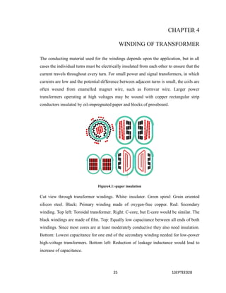
  • 1. 25 13EPTEE028 CHAPTER 4 WINDING OF TRANSFORMER The conducting material used for the windings depends upon the application, but in all cases the individual turns must be electrically insulated from each other to ensure that the current travels throughout every turn. For small power and signal transformers, in which currents are low and the potential difference between adjacent turns is small, the coils are often wound from enamelled magnet wire, such as Formvar wire. Larger power transformers operating at high voltages may be wound with copper rectangular strip conductors insulated by oil-impregnated paper and blocks of pressboard. Figure4.1:-paper insulation Cut view through transformer windings. White: insulator. Green spiral: Grain oriented silicon steel. Black: Primary winding made of oxygen-free copper. Red: Secondary winding. Top left: Toroidal transformer. Right: C-core, but E-core would be similar. The black windings are made of film. Top: Equally low capacitance between all ends of both windings. Since most cores are at least moderately conductive they also need insulation. Bottom: Lowest capacitance for one end of the secondary winding needed for low-power high-voltage transformers. Bottom left: Reduction of leakage inductance would lead to increase of capacitance.
  • 2. 26 13EPTEE028 High-frequency transformers operating in the tens to hundreds of kilohertz often have windings made of braided Litz wire to minimize the skin-effect and proximity effect losses. Large power transformers use multiple-stranded conductors as well, since even at low power frequencies non-uniform distribution of current would otherwise exist in high- current windings. Each strand is individually insulated, and the strands are arranged so that at certain points in the winding, or throughout the whole winding, each portion occupies different relative positions in the complete conductor. The transposition equalizes the current flowing in each strand of the conductor, and reduces eddy current losses in the winding itself. The stranded conductor is also more flexible than a solid conductor of similar size, aiding manufacture. The windings of signal transformers minimize leakage inductance and stray capacitance to improve high-frequency response. Coils are split into sections, and those sections interleaved between the sections of the other winding. Power-frequency transformers may have taps at intermediate points on the winding, usually on the higher voltage winding side, for voltage adjustment. Taps may be manually reconnected, or a manual or automatic switch may be provided for changing taps. Automatic on-load tap changers are used in electric power transmission or distribution, on equipment such as arc furnace transformers, or for automatic voltage regulators for sensitive loads. Audio-frequency transformers, used for the distribution of audio to public address loudspeakers, have taps to allow adjustment of impedance to each speaker. A center-tapped transformer is often used in the output stage of an audio power amplifier in a push-pull circuit. Modulation transformers in AM transmitters are very similar. Dry-type transformer winding insulation systems can be either of standard open-wound 'dip-and-bake' construction or of higher quality designs that include vacuum pressure impregnation (VPI), vacuum pressure encapsulation (VPE), and cast coil encapsulation processes. In the VPI process, a combination of heat, vacuum and pressure is used to thoroughly seal, bind, and eliminate entrained air voids in the winding polyester resin insulation coat layer, thus increasing resistance to corona. VPE windings are similar to
  • 3. 27 13EPTEE028 VPI windings but provide more protection against environmental effects, such as from water, dirt or corrosive ambients, by multiple dips including typically in terms of final epoxy coat. 4.1 Practical Transformer Winding:- Figure 4.1. practical transformer winding In the good old times it was a matter of fact that every electronic hobbyist or technician would wind himself any power transformers he needed, and rewind any that burned out. Unfortunately, nowadays transformer winding is fast becoming a lost art, and I have seen many people despair about where to find some very specific transformer, or pull their hair out about the cost of having one professionally wound to specifications. Since I started in electronics, as a 12 year old boy, I have always wound my own transformers. I started using the basic, but useful instructions provided in The Radio Amateur's Handbook of the time, and later I came to better understand how transformers work, which enabled me to optimize a given transformer for the intended application. Following a request by many readers of my web site, I've added this page, which is complementary to the previously published Transformers and coils. You should first read
  • 4. 28 13EPTEE028 (and understand!) that page, before trying to design any transformer. Then come to this more practically-oriented page, to learn some tricks and hints about the design process, and about hands-on winding. This page addresses mainly single-phase power transformers in the power range from about 1 watt to 10,000 watts, operating at line frequencies, but much of what's described here can be applied to a wide range of other transformers too. Figure 4.2 transformer LV winding Let's start with the materials. To make a typical transformer, you need the iron laminations for the core, enameled copper wire of several different diameters for the windings, a bobbin (or some material to make one), insulating material to apply between wire layers, between windings, around the whole winding assembly, and on exposed wires, and in most cases it's also a good idea to use an impregnation varnish. The photo here shows several stacks of iron E-I laminations, two coils of wire (with cardboard protecting the wire from damage), one roll of thick, stiff Pressspan, another roll of NMN laminate (we will soon see what that is), two small bundles of spaghetti for wire protection, and a can of transformer varnish. Add to this some glue, cotton straps, ropes, adhesive tape, terminals, bolts, angle iron, and other small material, and that's it.
  • 5. 29 13EPTEE028 4.1.2 Low voltage winding All these materials are sold by companies specializing in transformers and parts for transformers. Enameled wire is also sold by many other distributors, but is usually cheapest at the places that sell it together with the other materials. You will have to dig into the phone book or some other directory to find these companies, since they don't usually have a shiny nice store in the downtown shopping mall! Transformer iron is an alloy of iron with silicon and some other minor components. It's characterized by a relatively high permeability, very high saturation flux density, relatively low hysteresis loss, and relatively high specific resistance. This latter factor, along with the practice of using the material in thin, insulated sheets, reduces the power losses produced by eddy currents. Figure 4.3. transformer assembling The most common shape of these sheets is shown at right. It's the classic "economy E-I" shape. Why it's called E-I should be pretty obvious when looking at the photo! But the explanation for "economy" might be a bit more elusive: It's because at the exact proportions shown in the photo, the I's are nothing else than the cutouts to make the windows in the E's, when two E's are cut facing each other! This allows stamping E's and
  • 6. 30 13EPTEE028 I's out of a large steel sheet, without any wasting of material, except for the little round bits cut out of the bolt holes. By the way, small laminations often don't have such bolt holes, and such cores are held together by clamps instead of bolts, or even welded. The lamination in the photo is a large one, as the comparison with my hand shows. It's an E80 (the center leg is 80mm wide), typically used for transformers in the 3 to 10 kilowatt range! In any E-I lamination you are likely to encounter, the center leg is twice as wide as each of the other parts. This is because the entire magnetic flux has to go through the center leg, but then splits up, with one half of the flux returning through each of the side legs. If you ever come across a lamination that has all three legs of the same width, then you are looking at a lamination intended for three phase transformers! Such an economy E-I lamination like shown here has completely fixed proportions, beyond the rule above, that stem from the need to cut the I out of the winding window of two E's facing each other: If the center leg is 2 units wide, then the window is 1 x 3 units, the total E is 6 x 4 units, the I is 1 x 6 units, and so on. Not all laminations follow the "economy" proportions, though. Here is an example of a lamination that comes in one piece, instead of being divided into an E and an I, and that has the windows proportionally much larger than the E-I lamination shown above. Such a lamination is a bit more expensive to make, because the steel cut from the windows is wasted, unless the manufacturer can find some other use for it. But being able to accomodate a much large winding assembly, it has some advantages in certain cases. These "non-economy" laminations were quite usual in Europe, many years ago, but nowadays copper is so much more expensive than steel, that transformers are usually designed to use more steel and less copper. And for that goal, the economy lamination is very well suited.
  • 7. 31 13EPTEE028 The laminations should be thin, and reasonably well insulated from each other, to reduce eddy currents to an insignificant value. Typical thicknesses vary from 0.2 to 0.5mm, but higher frequency transformers (audio) use much thinner ones, while extremely large transformers might use slightly thicker ones. The insulation is often applied at the factory that makes the big rolls of steel sheet, even before stamping the E's and I's. Different kinds of insulation are used: A thin oxide layer, a thin layer of enamel, or any of several chemical processes. Antique transformers sometimes even used very thin paper! When I was young, patient and overly eager to do things right, I painted each and every E and I for my transformers, using diluted transformer varnish, to make a thin, nice layer. The photo shows the steel for a 200 watt transformer, drying. Later, getting old and lazy, I noticed that the layer of rust on old, recycled laminations is more than enough insulation, and that the very thin and imperfect insulation that comes on new laminations is enough too, even if it takes only a light scratch with the multimeter's test probe to puncture it and get through to the steel. We don't need perfect insulation between the sheets! We only need enough resistance to reduce eddy currents to a low level. Transformer steel is not all born alike. Manufacturers will provide data sheets about their products (often on their web sites), where you can see what they offer. There are usually many grades, with vastly different loss characteristics. At a given flux density and frequency, a good material might have ten times less loss than a cheap material! So it pays to look, investigate, and decide intelligently what to buy. Thinner sheets normally have lower loss, and the rest of the secret lies in the exact alloy. In any case, you need to know what material you have, to be able to make a meaningful transformer design! Some transformer steel is grain-oriented. That means that when rolling the steel sheets, a process is used to align the crystalline grains in the direction of the rolling. This kind of material has particularly good behavior when the magnetic flux is aligned with the direction in which the sheet was rolled, but is worse than standard material in the perpendicular direction. Such grain-oriented material is ideal for toroidal cores, which are
  • 8. 32 13EPTEE028 made by coiling up a long strip of steel, but is not a large improvement for E-I laminations, because in these a significant portion of the material has to work with the flux perpendicular to the rolling direction. Enamelled copper wire comes in many different diameters, and with several different kinds of enamel. The diameters vary from less than that of a hair, to about that of a child's finger. Different standards exist for the wire diameter. A very common one is American Wire Gauge, shortened to AWG, which is used in much of the world. Britain has its own standard, and in many countries the wire is specified simply by its diameter in millimeters. Thick wires usually are coated with a sort of enamel that is very tough, an excellent insulator, highly heat-resistant, highly resistant to solvents, and that clings to copper even better than dirt does to children! This enamel is usually yellowish clear, so that the wire coated in it looks mostly copper-colored, but many exceptions exist. To solder the ends of these wires, it's necessary to scrape off the enamel, using a sharp knife or similar tool. This procedure would be too difficult with a thin, fragile wire, so that these thin wires are instead covered with an enamel that has most of the same characteristics of the other one, except the heat resistance: It will melt and turn into solder flux at a temperature a common soldering iron easily achieves! . . Figure 4.4 low winding manufacturing
  • 9. 33 13EPTEE028 This allows easily soldering these wires, without previously stripping them. But transformers using this latter kind of wire enamel cannot survive temperatures as high as those using only the former kind of wire enamel. The red wire on the right side in this photo has this kind of enamel. But be careful with colors! The clear wire on the extreme left side also has solderable enamel, while the dark violet one in the middle is of the non- melting variety! The thickness of the enamel layer depends on the wire thickness, the manufacturer, and can sometimes be chosen: Some manufacturers will offer the wire with seeral different thicknesses of enamel. In any case, the diameter specified by a certain AWG number refers to the copper diameter, so that the complete wire, with enamel, will be slightly thicker than what the AWG standard tells! Figure4.5. Low voltage side winding Here is a wire table for AWG wire. It shows the AWG number, the diameter in millimeters excluding the enamel, the approximate typical total diameter including the enamel (but this varies somewhat), the cross sectional copper area in square millimeters, the area of the square of window space occupied by that wire in a transformer (including the enamel, of course), the current carrying capacity at a typical, average value of current
  • 10. 34 13EPTEE028 density, the resistance in ohms per meter, and finally how many meters of that wire come in one kilogram, because enamelled wire is usually bought by weight, not length. This table has wires from AWG #1 to #40, and for the thickest ones I didn't calculate all data. But you should be aware that there are wires exceeding this range! The thinnest I have ever used was #46. It breaks when you blow at it! The photo here shows a #39 wire lying on a #7 wire. The hairy thing below is my floor carpet. Note that even this #39 wire is not much thicker than the hairs of this carpet! It's interesting to note that every three AWG numbers, the cross sectional area exactly doubles. Any deviation from this in my table is due to approximation errors.Modern transformers of small to moderate size are usually wound on plastic bobbins. Here you can see simple ones. Some bobbins have pins or terminals molded into them, others have one or two divisions. Some don't have the slits for terminals, which the ones shown here do have 4.1.2 High voltage winding Figure 4.6 High voltage winding transformer
  • 11. 35 13EPTEE028 Typically for a given size of E-I laminations, bobbins will be available in two or three sizes, accomodating different numbers of steel sheets. So you can vary the amount of steel in your transformer not only by choosing the lamination size, but also the height of the lamination stack! Here is a little transformer using a divided (or split) bobbin. This is very practical, because it completely separates the primary from the secondary winding, making it much easier to achieve the degree of insulation required for safety. More about that later. If you cannot find a plastic bobbin in the proper size, don't despair! Bobbins can be easily made from materials such as strong cardboard, or Pressspan, which is nothing else than a particularly strong cardboard. The bobbin shown here was made from 1.5mm thick Pressspan, which is really too thick for this small bobbin, but I had nothing better on hand. The pieces are cut to size using a sharp knife (X-acto or the like), and glued together with cyanoacrylate adhesive (instant bonder). The clever structural design of this super high tech bobbin holds it together perfectly while the glue sets! You must make the inner dimensions of the bobbin core a tad larger than the transformer center leg, but JUST a tad, no more, unless you want to waste valuable winding space! The sides can be made pretty tight to the size of the laminations, because if they don't fit at the end, they are easily enough cut or filed down, even after the winding has been made. But the length of the bobbin must be smaller than the window length of the core, by as much as 2 or 3%, plus any tolerances of your manufacture! Because it is critically important that the E's and I's can touch each other properly, without being kept separated by a bobbin that deformed during winding, and grew! Be sure to at least break the corners as shown here, or even better, round them off. Otherwise the wire is guaranteed to tangle at the sharp corners during winding, and a wire loop sticking out of the completed winding can ruin the whole thing!
  • 12. 36 13EPTEE028 Note that the junction of the bobbin's center piece is placed in the middle of one side, and not in a corner. It's next to impossible to produce a reasonably symmetrical and precise bobbin when placing the junction in a corner. If the material is thin compared to the bobbin size, the junction should be made by overlapping the material. Of course, the overlapped junction is always placed on one side that will end up outside the core window, so that the added bulk has little detrimental effect. To bend this thick material in reasonably clean right angles, my technique is to use a sharp knife to cut out a 90 degree wedge from the inside, along each bend line, leaving only the outer third of the material intact. After that admittedly cruel treatment, Most antique transformers, and many of the larger modern ones, don't use a real complete bobbin. Instead, they use only the center former, and no sides at all! It takes some tricks and practice to wind a transformer like this without having the whole thing come apart many times over during winding, but for people who have acquired enough practice, it's faster than making a real bobbin! Further down, I will show you a trick to make this kind of transformer, with high quality. Note in this photo how the Argentinian maker of this transformer (back in 1931!) used insulating material of several different thicknesses for the bobbin center, the interlayer insulation, the interwinding insulation, and the terminal support. You might ask why any insulation material is required at all, if the wire is insulated by its enamel layer! Well, the enamel is very thin, and easily scratched. It might survive as much as a few thousand volts, but it might also break down with a lot less! It depends on type, condition, thickness, temperature, and other factors. So, wherever the voltage can exceed a few tens of volts, some additional insulation needs to be used. Specially between the primary and secondary, safety regulations ask for an insulation good for at least 4000 volts, to avoid electrocuting somebody when there is a lightning transient on the AC power network.
  • 13. 37 13EPTEE028 In antique transformers, the most usual insulating material was paper, impregnated with something like beeswax, tar or the like. This impregnation had several purposes: Mainly, it would seal the pores of the paper, making it a really good insulator, while without the impregnation it would only insulate as well as the same thickness of air! But in addition, it kept moisture out, it helped stick the thin wires in place during winding, and it improved the thermal conductivity of the completed winding assembly. Modern insulating materials are far superior. Plastic sheets such as Mylar provide excellent dielectric strength and have no pores, so they require no impregnation to realize their high degree of insulation. Nomex instead, with its fibrous structure, behaves like paper, but both Nomex and Mylar are much better than paper at surviving high temperatures! This is a key characteristic of insulating materials: The temperature class. It's coded with a letter. Paper would have an A or B rating, telling that it is fine for temperatures not much above that of boiling water. Different plastic insulation materials instead are routinely available in classes as high as F, G or even H! They can safely run much hotter than paper can. The photo shows an NMN insulating sheet. This is a sandwich of a Mylar sheet embedded between two layers of Nomex. The Nomex will eagerly soak up and distribute the impregnation varnish (or the oil, in an oil-inmersed transformer), while the Mylar will provide safe insulation even in places that for any reason stayed dry! I love this material. It's thermal class G, if I remember right. Insulation materials come not only in many different variants, and temperature classes, but of course also in many different thicknesses. You choose the proper thickness so that it has enough dielectric strength and mechanical strength, without taking up an undue portion of your valuable window space! Despite all modern materials, good old paper and cardboard is still used sometimes. Mostly in its form known by the German word Pressspan, which means "compressed chips", and is simply a very dense paper or cardboard.
  • 14. 38 13EPTEE028 It's very good practice to soak a completed transformer in some impregnation varnish. It will form fillets around wires, papers, and anything else. It will improve the insulation, make the transformer highly moisture-proof, glue everything together so that nothing can rattle, come loose, or chafe through, it will improve thermal transfer, and so on. Varnish comes in several thermal classes, just like the insulation material, and also it comes in variants that dry at high temperature, or at room temperature. My experience is that no varnish ever fully dries at room temperature, and when you start using the transformer and it warms up, the varnish inside will start drying, and stink! So, it's necessary to apply heat anyway, regardless of what sort of varnish you use. Now that you have turned into a person very knowledgeable about transformer materials, let's turn to those pesky questions such as "how many turns do I have to wind?" or "what wire size?" or "how much power will I get?" There are three typical situations: 1 You need to repair/rewind a transformer that burned out. 2 Your want to rewind an existing transformer, to produce the voltages and currents you need, which are different from the original ones. A variation of this case is when you want a certain voltage, at the highest current that transformer can provide. 3 You have fixed specifications, want to design a transformer to optimally meet them, and you will buy the core and all other materials. Let's start with the first case. You MUST find out why that transformer failed! A correctly designed, correctly built and correctly used transformer is, for all practical ends, eternal. If it failed, there is a reason. If you know that the transformer was shorted, overloaded for a long while, exposed to intense lightning transients, thrown into water, gnawed through by rats, exposed to corrosive substances, or anything like that, then your best approach is to unwind it, count the turns, measure the wire sizes, and rewind it exactly as it was originally made.The photo shows an antique speaker field coil, mounted in my winding
  • 15. 39 13EPTEE028 machine. I unwind coils by pulling off the wire while having the thing spin in the machine, so that the turns counter in the machine will do the pesky job of keeping count. The problem, as illustrated here, is often that thin wires won't come off nicely! They are stuck in place, and will break, then entire chunks of wire will come off all together. This often makes it hard to accurately count the turns. In such cases you might simply estimate how many turns you didn't count. Or you can collect all the pieces of wire you removed, weigh them, calculate the amount of wire from there, and calculate the turns number from it. Or, instead of unwinding the coil, cut it with a knife or better a Dremel tool, remove it in one block, measure the cross sectional area of the entire winding, then remove a little piece of wire to measure the diameter, and finally calculate the number of turns from this. Any of these methods will usually be precise enough for non-demanding applications, and none of it will be precise enough when you need anything critical. By the way, do you know how to precisely measure the diameter of a thin wire, when you don't have a micrometer screw? Simple: You wind 10 or 20 or even more turns tightly on a former (such as a screwdriver stem), measure the length of the coil with a common ruler, then divide by the number of turns to get the wire diameter. It's highly accurate. Sometimes it's even better than using a micrometer screw, which can flatten the wire if you apply too much torque! But there are cases when you have a burned transformer, and no good reason why it burned. It might have been a manufacturing defect, a huge transient, an overload that went undetected, but maybe - the Gods of Electromagnetics forbid - that transformer might have been misdesigned! In that case, painstakingly rewinding it with the same wire gauges and turn numbers as original, will only produce a transformer that will fail again. So, if you don't know why a transformer failed, re-do the design, and compare your results with what the manufacturer did! Many manufacturers are cheapskates, and use substandard transformers, in the hope that most clients will never use them intensively enough to blow them up! This sends you straight to the section about the third case, further down this page!
  • 16. 40 13EPTEE028 In the second case, when you want to rewind an existing transformer for new output values, very often the transformer will already have a properly wound and healthy primary winding. In such a case, keep it! There is no point in unwinding and rewinding the primary, if it is fine. The calculation work for such a transformer is quite simple: Before taking it apart, measure the voltage delivered by the secondary. Disassemble it, unwind the secondary, counting the turns, and calculate the number of turns per volt from this. Calculate the new number of turns you need for your desired voltage. Calculate what's the largest wire size that will comfortably fit in the available space. Get the wire, wind it, and assemble the transformer. The power rating will be the same as before, and this allows you to calculate the current you can safely draw, at your new voltage. Do you know what you can do with all that wire you remove from old transformers? Well, a super trendy wig, like the one shown here, modelled by my sister, is sure to catch everybody's attention! Otherwise, there isn't really much use for such wire. It comes out totally kinked, stretched, broken, scraped, with varnish, wax or tar sticking to it. Don't even dream about ever re-using it in any other transformer! power capability, with a reasonably simple, but nonlinear curve. This curve also depends on the quality of the core material, and several other factors. The next step is calculating how many turns per volt you need on this core. To this end, you have to decide how much flux density you will put through your core, and then you can apply the equations from Transformers and coils. The optimal flux density might be anything from 0.8 to 1.6 Tesla, and sometimes even outside this range! General rules of thumb are these:  Larger transformers use lower flux densities.  Better core material uses higher flux densities.  Transformers that are always energized, but rarely used at full power, use lower flux densities.  Likewise, transformers that work at full power whenever energized, use very high flux density.
  • 17. 41 13EPTEE028  Forced air cooled transformers use higher flux density.  Oil-immersed transformers use even higher flux density!  Higher flux density produces better voltage regulation.  Lower flux density produces less base loss.  Lower flux density is less likely to produce humming noise, and magnetic stray fields.  Lower flux density produces lower iron loss, but higher copper loss. I have seen many text books giving design equations that result in a flux density of 1 Tesla in each and every transformer you calculate by them, like if that were a sacred rule! If you come across any such book, BURN IT! It's nonsense! While 1 Tesla indeed tends to produce a workable transformer in most cases, in at least 70% of all situations it's far enough from the optimal value to warrant some effort toward optimization! Specially in small transformers, and in those using the better core materials. So, I suggest to start with a value chosen from the rules above, and then calculate the transformer based on this value, analyzing the losses, heating, voltage drop, efficiency, and so on. Then change the flux density, by 10 or 20%, and re-do all the calculations. You will see what I mean! There is a clear optimum value for flux density in each particular case, and this value is very often sufficiently removed from 1 Tesla to make you wonder why some book authors still copy that "magic number" from other, long gone authors! Most likely they have no idea about the matter they are copying. That said, sometimes I do wind my transformers for 1 Tesla, because there are cases when this is really a good value! The loss calculation isn't very hard: The manufacturers of transformer steel specify the loss of their products, as a certain amount of watts per unit of volume or weight, under certain conditions of frequency and flux density. And the better of these data sheets also contain curves, or give equations, to calculate the loss under different conditions. That's about the iron loss. The total loss of the transformer also includes the copper loss,
  • 18. 42 13EPTEE028 Figure4.7 first turn of transformer lv winding In this sheet, you enter your data in the green area, and watch what happens in the orange one. The first three values you have to enter are the ones that specify the core. First is the center leg width of the lamination used, in millimeters. The 100mm width given in the example is a pretty large lamination. You will typically use values between 12 and 50mm. The sheet is based on the proportions of the economy E-I core, so that you don't need to enter any other dimensions of the lamination. If you happen to be using a lamination that has different proportions than the economy E-I, you should still enter the width of the center leg, but later you will need to manually compensate for the larger available window, by increasing wire size beyond that calculated by the sheet, reducing the copper loss, and so on. The second value you have to enter about the core is the stack height, also expressed in millimeters. This is simply the height of the stack of E's, well compressed. This sheet does not allow you to enter the stacking factor, which tells how much of the stack is actually steel. There's always some little space used by insulation, and even wasted space due to imperfect compression. But the effect of this is small enough to ignore, as long as you compress the stack well enough!
  • 19. 43 13EPTEE028 Good stack heights to use are from the same as the center leg width, to close to twice that. Often you have the choice to use a certain lamination, stacked as high as the center leg is wide, or use the next smaller lamination, stacked much higher, with both options producing the same output. It pays to simulate both options, optimize each, and compare the efficiency, voltage drop, weight, and cost! The differences can be profound. And the third value is the loss factor of the steel material. This must be taken from the datasheet provided by the manufacturer of the lamination. My sheet expects this loss factor to be expressed in watts per kilogram of material, at a flux density of 1 tesla and a frequency of 50 hertz. Many data sheets include the value in this exact form, but those published by US companies might instead express the loss factor in an eclectic mixture of metric, CGS and Imperial units! If that's what you have, you will need to convert the value into its fully metric equivalent. You might want to modify the spreadsheet to do that. The value of 2 W/kg @ 1T and 50Hz is pretty representative for modern low cost laminations. A modern ultra low loss material might be a lot better, while an antique or ultra-cheap material might be significantly worse. The next three values in that column are pretty obvious: You have to indicate the primary and secondary voltages, and the frequency of operation. The secondary voltage refers to the open circuit (no load) voltage. And the frequency will usually be either 50 or 60 Hertz. If you enter a frequency far away from this, it's quite possible that the loss calculated for the material will be rather imprecise, so use this sheet with caution if you need to design a transformer for a very different frequency. In the right hand column, you have four values which are design decisions which you can vary somewhat. The first is the all-important flux density. Just try varying that value, and watch how things change in the orange output area! Specially, see what happens with the iron loss. I have already given guidelines about what flux density to use. Use them and see what happens in your case, when you change it.
  • 20. 44 13EPTEE028 The next is the amount of copper cross section you will allow for each ampere of current in the windings. Reasonable values are about 0.25 mm^2/A for very small transformers, increasing to 0.5 for large ones. 0.35 is typical for medium sized transformers (50 to 300 watts or so). When you adjust this value, the design of the transformer doesn't really change, but the sheet will calculate a new set of currents, power, voltage drop, efficiency and loss. With this parameter, you basically are telling the sheet how much you will stress a particular transformer. The fill factor expresses how much of the lamination's window will actually be filled with copper. It can never be very high, because a lot of that area gets inevitably filled out with the bobbin, the wire's lacquer, the air around the round wire, the insulation between layers, between windings, and some space is always lost due to sloppy winding, even if you are careful! The value of 0.4 used in this example has proven in practice to be achievable without much trouble. If you wind very carefully, and minimize the amount of space devoted to insulation, you should be able to get up to 0.5. But don't push this number too much, or you will end up with a transformer design that you cannot actually wind! On the contrary, if you have never before wound a transformer, and will do so by hand, in a ragged, ugly winding, it might be a good idea to design the transformer with an even lower fill factor, such as 0.3, to make sure you will be able to fit all the turns! Of course, using a lower fill factor means simply using thinner wire, and this means that at a given amount of loss and heating, you get less current. The fill factor can be pushed beyond 0.5 when you wind a transformer with square wire (instead of round), or with copper tape separated by thin layers of insulation. But square wire is hard to find and a hassle to wind properly, and tape winding is acceptably easy only for transformers that have rather few turns. This is often the case with high frequency transformers used in switching power supplies, but not at line frequencies. The temperature rise defines how many Kelvins (same as degrees Celsius in this case) hotter than the surrounding air and objects you want your transformer to run. You need to carefully choose this value, according to the highest ambient temperature (inside the equipment!) at which your transformer will have to work, also taking into account the
  • 21. 45 13EPTEE028 highest temperature your wire, insulation material, varnish, glue, etc, can survive. And what's most difficult, you will also need to estimate the thermal gradient from the innermost wire turns (the hottest ones) to the transformer's surface! Calculating all this can be quite hard, and I can't give you simplified equations for it. Maybe you can find them elsewhere. The value of 70 Kelvins which I used in the example design is relatively high. This is so because this transformer would work in open air, not inside a housing, where the ambient temperature is never above 25 degrees Celsius; also, I used class G or higher insulating material, wire and varnish throughout; and finally, this transformer was carefully impregnated with varnish, giving it a reasonably good thermal conductivity between winding layers. If your transformer will not be impregnated, or use class A or B insulation material (paper), or run inside a cabinet that can be hot, then you will need to use a lower value for allowed temperature rise then my 70 Kelvins! Finally, you can enter your local and current prices for enameled copper wire and transformer steel laminations, to have the sheet calculate the cost of these main materials for your transformer. All the additional cost, for the bobbin, insulation material, terminals, bolts and so on, is usually small compared to the copper and steel cost. The most expensive item is usually the wire, by far. The first two lines of the orange output area of my spreadsheet show some basic results for that transformer: The cross sectional area of the magnetic core and of the winding window, also the total copper area (after applying the fill factor), the turns per volt constant that will be valid for all windings on this transformer, and the average length of one turn, which is calculated as the average between the length of a wire that goes around the center leg touching it, and one that goes around the entire winding package, touching the outer legs. Then you have a line for the primary winding and one for the secondary. Each of these lines tells you the number of turns, the length of the wire need to wind it, the copper cross sectional area of the wire, and the nominal current that will flow at full rating. The
  • 22. 46 13EPTEE028 number of turns isn't rounded off, so you will have to do that, because you can't wind a fraction of a turn. You can fiddle with your voltage data to get the sheet to show round numbers of turns. The wire length is based on the length of the average turn, so this will be correct only if you wind the primary and secondary side-by-side, on a split bobbin. If instead you wind the secondary on top of the primary, you will need less wire than calculated for the primary, and more than calculated for the secondary. Anyway, these lengths are not very useful in practice, because wire is bought by weight, not length. The main situation where they are useful is when you have to wind a transformer with several thin wires in parallel, because these are much easier to bend than one thick wire. In such a situation, it's great to know how long the total winding is, so that you can cut the strands and twist them together, before you start winding. The remainder of the orange output area is divided into two columns. The left one shows some important performance data of the transformer: There is the input power, expressed in voltamperes, which is really more correct than watts. The value calculated by the sheet does not include the magnetizing current; calculating it would need additional information about the core. But in medium to larger transformers, at least, the magnetizing current tends to be small enough to be ignored. Then comes the percentual power loss of the transformer, at full load. This includes both the iron loss and copper loss. The output power is of course the input power minus this loss. Then we can see the voltage drop at full load. The value is calculated only from the resistances of the windings. Any additional loss caused by imperfect coupling between the windings is not considered here. So, if you use a poor core or winding technique, that results in bad coupling, you should expect a somewhat higher voltage drop. Just for user convenience, the sheet also calculates the output voltage under full load, which is based on the voltage drop calculated above. Below comes the weight of iron laminations and copper wire used in the transformer. This has several purposes. One is knowing how heavy the beast will be, of course. The
  • 23. 47 13EPTEE028 other is knowing how much material you have to buy! If you use side-by-side winding of the primary and secondary, you need to buy one half the calculated copper wire of each size (plus some extra, of course, to be on the safe side). If instead you wind the secondary over the primary, you need a little less than half of that weight of the primary wire, and a little more than half that weight of the secondary. And then, the sheet will calculate the total cost for laminations and wire, and also divide this by the power, to give the cost per watt for your transformer, which is a good figure of merit which you might want to optimize. Even while this calculation doesn't include the cost for insulating material and other odds and ends, it's still a good reference. The right side column of this area is about thermal matters. These tell whether your transformer will survive, so don't take them lightly! The sheet calculates the power loss in the iron, in the copper, and adds them to get the total power loss. Copper loss is calculated at ambient temperature, though. When the wire heats up, its resistance increases, and so its loss increases too! For this reason, take the calculated value with a small grain of salt. The same is true for the voltage drop end efficiency calculations! You need to be aware of the fact that the iron loss is essentially constant, regardless of the load placed on the transformer, except for a little effect caused by voltage drop in the windings reducing available magnetizing voltage, which causes a slight decrease in core loss when the load gets higher ! The loss in the wire instead increases with the square of the current taken from the transformer, and the value calculated by the sheet is for the full rated current. This gives you some big help in optimizing a transformer design. For example, a transformer that will spend lots of time plugged in, but idling or loafing along at low load, will see very little copper loss, but the iron loss will be there all the time. So, you should design that transformer with a relatively low flux density, resulting in low core loss, accepting a higher copper loss instead, by setting a smaller value of copper cross section per ampere. After all, most of the time the rated design current won't be present, so that the very high copper loss resulting in the calculation will be present only very
  • 24. 48 13EPTEE028 rarely, for short times! Transformers used in radio communication equipment, in audio amplifiers, and many other uses, are best designed in this way. The opposite case happens with transformers that are energized only briefly, but run at full output power whenever energized. Examples of such use are microwave ovens and spot welders. In such a transformer, iron loss always happens at the same time as copper loss, and you can optimize the transformer to get the lowest total loss, regardless of how it distributes between the iron and the copper. Even more, you might intentionally place more loss into the core than the windings, based on the fact that the core is less prone to be damaged by heat, has more thermal mass, and that the short operation time won't allow the peak heat to distribute through the transformer! And then, such a transformer that operates only for short times can be designed to have a really huge loss, because it will have time to cool off between uses! These things are what makes microwave oven transformers that deliver 800 watts be as small as a 200 watt transformer intended for continuous service at low rate, and run at a flux density of 2 teslas or even more! The heat produced by a transformer has to be dissipated to the surrounding air. The spreadsheet calculates the approximate total surface area of the transformer, and finally calculates a required thermal transfer coefficient, which expresses how much power the transformer needs to dissipate per unit of surface it has, and per temperature rise allowed. This coefficient tells you how difficult it will be to keep this transformer cool enough to survive! The violet area below this coefficient includes referential values (not calculated by the sheet) which you can use to try judging whether your transformer will be OK, when you have it in a tight area, in a more open area, cooled by a fan, or immersed in oil. I have my doubts about these values, specially aout the value for the oil- immersed transformer, so please take these with a big grain of salt, and let me know if you have any further, better, or more reliable data. Anyway, my transformers designed for a coefficient of around 12 have all survived so far, even while getting quite hot at full load, so this value can't be too far from the truth.
  • 25. 49 13EPTEE028 A typical design sequence using this spreadsheet would be to first enter the tentative core size and loss, the required voltages and frequency, then start with something like 1 tesla and 0.35mm^2/A, leaving the fill factor at 0.4 and setting the temperature rise according to your transformer's materials and environment. Then you can observe the power and current it would operate at, and the losses, efficiency, voltage drop, and also you would get the thermal transfer coefficient which you can compare to the table to gain an idea of whether the transformer will survive. You can then tweak the flux density and current density, trying to get the characteristics into the range you need, without exceeding the thermal possibilities. If you just can't find a combination that provides what you need, you will have to try with a larger (or lower loss) core. Then you might want to explore several different core sizes, optimizing each, and watch the cost, finally settling for the design that best provides what you need, at the lowest possible cost, while staying in the survivable thermal range. This work with the spreadsheet is only the first step, though. When you have arrived at a good design using the sheet, you need to tweak it to make it buildable with real, available material! For example, you cannot get wire in any desired diameter. The sheet doesn't know that; It might ask you for a wire measuring 1.2345 square millimeters, or anything else. It's your job to see what wire you can actually buy, or maybe what wire you happen to have in stock, and adapt the design. The AWG standard is quite finely stepped, so you don't need to change the design very much to adapt it to standard AWG sizes. But I have heard that in the US many stores only sell the even numbered AWG sizes of wire! That's odd (pardon the pun), since even down here in less developed Chile I can easily buy all AWG sizes, even and odd. If you are limited to even sizes only, you will have to make bigger compromises. A good approximation technique is to round the wire size to the nearest AWG size, or if the values calculated fall just in the middle between AWG sizes, you might want to use the next thicker wire for the primary, and the next smaller wire for the secondary. That way the final losses and the amount of space required will be almost exactly the same as calculated by the sheet.
  • 26. 50 13EPTEE028 If your transformer uses lots of turns of thin wire, you are about ready to start winding at this point. But if it uses a winding that has few turns of a thick wire, you should check how well (or how poorly) that wire fits in an integer number of layers, considering the width of the bobbin, and about 5% of lost space due to the wire not being perfectly straight. The problem is this: If the sheet calculates you need 48 turns of a certain wire size, and it happens that you can fit only 15 turns per layer, then you will end up with three complete layers, plus one additional layer in which you have just three turns! So the total height taken up in the window by those 48 turns will be as much as 4 complete layers, that could have 60 turns! Consequently, the winding might end up too high, and won't fit the window! Then you cannot assemble the core, and you have to unwind that winding, throw the wire away, get new (thinner) wire, do it again... you get the idea. Try to avoid such frustration! When you are in the situation just described, it would be wise to try the next smaller wire size. It's very likely that this smaller wire size would accomodate 16 turns per layer, thus allowing you to wind the 48 turns in three nice, clean, complete layers, and using up a little bit less space than calculated by the sheet. This can in turn allow you to use the next larger wire size for the other winding, which will almost completely compensate for the higher loss and voltage drop of the smaller wire you used for the 48 turns! Putting it in short words, you have to pick the best wire sizes for your transformer so that their cross sections are close enough to the calculated values, but still allow a good, space-saving distribution on the bobbin and thus inside the window area of the core. Sometimes you might end up with a high current transformer requiring a very thick wire. Such a wire is very stiff! If the bobbin is small, you might not be able to bend that thick wire tightly enough around the corners of the bobbin. The result would be a huge loss of space, and the completed winding wouldn't fit in the window, making it unusable. To work around this problem, you can replace one thick wire by a bundle of seven wires, each of which is one third as thick as the single wire. Such a seven wire bundle twists very nicely into a round cable, and is more then 20 times as flexible as the single thick wire! It costs only very slightly more money, and performs great. So, this is the way to go
  • 27. 51 13EPTEE028 when you have a need for such thick high current conductors. It's good to know that an AWG number 10 units higher is roughly one third the diameter. So, if you would need a #7 wire and this is too thick to wind comfortably, you can use 7 strands of #17, lightly twisted together. Sometimes instead of using one thick wire you will also find it convenient to wind with two or three thinner wires in parallel, without twisting them. This technique can significantly ease the distribution of a winding in entire layers. Another hint: Most transformers use some thin and some thick wire. For transformers that have the windings on top of each other (instead of side-by-side), I suggest to always first wind the windings that use the thin wire, then the ones using thicker wires, regardless of which will be primary and secondary. This allows to wind the stiffer wire on the outside, where the bending radius required is a lot larger and thus less demanding. Whether the primary is under or over the secondary has no significant effect on performance. You might have noticed that my spreadsheet only considers transformers that have a single primary and a single secondary. But many transformers use several secondaries, and some use two or more primaries! In such cases you will have to do some more work manually. You should use the sheet to calculate the transformer, simulating only the main secondary, tweaking it for the total power, and then manually reduce the wire size of that secondary proportionally to the percentage of the total transformer power this secondary will have to deliver. Then you can add the other windings, calculating their turns number from the turns per volt calculated by the sheet, and the wire size from the current they have to carry, and the mm^2/A you selected. Or if you have two equal secondaries (or two equal primaries!), you can let the sheet calculate a single secondary (or primary) of twice the voltage. That will produce the correct number of total turns and wire sizes. You only have to remember to cut the wire after having wound half of the turns, bring it out, start again and wind the second half! You might have noticed that I didn't assign additional wire cross section to the primary, to account for the magnetizing current. The reason is that the magnetizing current is
  • 28. 52 13EPTEE028 normally much smaller than the main current, and on top of that, the magnetizing current is 90 degrees out of phase with the main current! The vectorial sum of the main and magnetizing currents is so little higher than the main current alone, that there is usually no need to consider the difference. You might also miss any discussion of core saturation. The problem is that's quite hard to discuss saturation of silicon steel cores, because they just don't saturate at a well defined level of flux density! Instead, the saturation is quite gradual: It might start at a level as low as 0.5 tesla, become more noticeable at 1 tesla, then the curve bends further, but even at 2 tesla there might be a significant amount of permeability left! The effect of this is that with increasing flux density, the magnetizing current increases more sharply, but it would be really hard to reach a level where the saturation makes the transformer stop working. So, the most important consideration about flux density is the sharply increasing core loss. Only when you are using very high flux density, would it be a good idea to allow some additional cross section for the primary wire, to accomodate the larger magnetizing current.