SlideShare a Scribd company logo
1 of 33
Download to read offline
1
CHAPTER 1
INTRODUCTION
TRW at Patiala was established in 1960 but actually started working in the 1966-67. It is the
most important department of the PSEB. In this workshop, the distribution transformer, which
can be damaged during working period, will be repaired of different capacities. Mainly
25KVA, 63KVA, 100KVA and 200KVA Transformers will be repaired in TRW. The monthly
output of this workshop is nearly 120 units.
1.1. The Detail Of These Workshops Is As Under:
1.1.1. 2 pilot workshops for manufacturing PCC Poles (Muktsar & Mohali).
1.1.2. 2 central workshops for fabrication of fitting & accessories (Patiala & Amritsar).
1.1.3. 3 workshops for fabrication of HT & LT coils (Patiala, Amritsar & Jagraon).
1.1.4. 4 workshops for repair of failed power transformers (Jalandhar, Ludhiana, Malerkotla &
Amritsar).
1.1.5. 11 TRWs (Transformer Repair Workshops) for repair of failed distribution transformers
(Jalandhar, Patiala, Malerkotla, Kotakpura, Nakodar, Jagraon, Doraha, Fatehgarh Churian & 3
at Amritsar).
1.2. Transformer
1.2.1. A transformer is a static device which transfers ac electrical power from one circuit to
another circuit at same frequency.
1.2.2. When the voltage level is raised on the output side (v2>v1) the transformer is called a
step-up transformer.
Fig.1.1. Basic Form of Transformer
2
1.2.3. When the voltage level is lowered on the output side (v1>v2) the transformer is called a
step down transformer.
1.2.4. The winding to which supply is connected is called a primary winding and to winding to
which a load is connected is called a secondary winding.
1.3. Working Principal
The basic principle of transformer is Electromagnetic Induction. When a.c. supply of voltage
‘Vp’ is connected to primary winding, an alternating flux is set up in the core. This alternating
flux when links with the secondary winding an e.m.f. is induced in it called mutually induced
e.m.f. The direction of this induced e.m.f. is opposite to the applied voltage ‘Vp’, according to
Lenz’s law. The same alternating flux also links with primary winding and produces self-
induced e.m.f. ‘Ep’. This induced e.m.f. ‘Ep’ also acts in opposite direction to the applied
voltage ‘Vp’ according to Lenz’s law. Although, there is no electrical connection between
primary and secondary winding, but electrical power is transferred from primary circuit to
secondary circuit through mutual flux.
1.4. Necessity
In our country usually electrical power is generated at 11 kV. From economic reasons ac power
is transmitted at very high voltages (220kV or 400 kV ) over long distances, therefore a step-
up transformer is applied at the generating station .then to feed the different areas, voltages are
stepped down to different levels by transformer at various substations. Ultimately for utilization
of electrical power the voltage is stepped down to 400/230v for safety reasons thus transformer
plays an important role in the power system.
Here in the T.R.W, we are dealing with distribution transformers only .the major difference
between power and distribution transformers is given below:
1.5. Difference Between Power And Distribution Transformers
1.5.1. Power Transformers: these transformers are used to step-up the voltage at the
generating station for transmission purposes and to step down the voltage at receiving stations
these transformers are of large sizes( generally above 500 kVA ) these transformers are usually
operate at high average load, which would cause continuously heavy copper loss, thus
affecting their efficiency. To have minimum losses during 24 hours, such transformers are
designed with low copper losses.
3
1.5.2. Distribution Transformer: These transformers are installed at the distribution
substation to step down the voltage .these transformers are continuously energized causing the
iron losses for all the 24 hours, when generally the load fluctuates from no-load to full-load
during this period .to obtain high efficiency such transformers are designed with low iron
losses.
Fig.1.2. Distribution Transformer
Fig.1.3. Power Transformer
4
CHAPTER 2
CONSTRUCTION
2.1. Three Phase Transformer: In core type three phase transformer the core has three limbs
of equal area of cross section. Three limbs are joined by two horizontal members called yoke
.the area of cross-section of all the limbs and yoke is the same since at every instant magnitude
of flux setup in each part is the same. The core consists of laminations of silicon steel material
having oxide film coating on both the sides of insulation. The lamination are usually of “E”
and “I” shape and are staggered alternately. These type of transformers are usually wound with
circular cylindrical coils the low voltage winding is wound nearer the core and high voltage
(H.V.) winding is wound over low voltage winding.
Insulation is always provided between the core and low voltage windings and between low
voltage winding and high voltage winding. Here TRW we are dealing with “DY 11” 3 phase
transformers connected in GROUP 4 (plus 30⁰ phase displacement) that mean the high voltage
winding is connected in delta and low voltage winding is connected in star and that the low
voltage line pharos leads the corresponding high voltage line pharos by 30⁰. As the distribution
transformer step-downs to 11kV/400v, the high voltage winding (or primary winding in this
case) is connected in delta that mean that all the six out coming terminals are connected in such
Fig.2.1. Core Type Transformer
5
a manner so as to form a delta connection similarly the low voltage winding (or secondary
winding in this case) is connected in star so as to obtain a neutral point or wire that means that
all the six out coming terminals are connected in such manner so as to obtain a common neutral
point.
1. H.T bush terminal 11. Drain off point
2. H.T bush insulator 12. Transformer core
3. H.T terminal lead 13. L.T winding
4. L.T bush /terminal 14. H.T winding
5. L.T bush insulator 15. Cooling tubes
6. L.T terminal lead 16. Lifting hook
7. Conservator tank 17. Oil level indicator
8. Breather 18. Main tank cover
9. Silica gel (filled in) 19. Base frame
10. Oil filling point 20. Separator sheet
Fig.2.2. Cut-Off Pictorial View With Parts Description
6
2.1.1. Core: The transformer core is made up of silicon steel or sheet steel with 4% silicon. In
addition to this the sheets are laminated and are coated with an oxide layer to reduce the iron
losses. The thickness of the lamination is 0.35 to 0.5 mm. The purpose of the core is to provide
a magnetic path of low reluctance between the two windings so that whenever one winding is
exited, the flux established by the winding will link fully with the other winding without any
appreciable leakage. The permeability of the material used for the core must have a high value
(µr >1000), since the reluctance of the magnetic path is inversely proportional to µ.
2.1.2. Windings: The winding which receives the electrical energy is called the primary
winding and the winding which delivers the electrical energy is known as secondary winding.
Earlier the windings are made up of high grade copper but due to high cost of copper, aluminum
conductors are used nowadays. The windings are provided with insulation such that any one
turn will not come into contact with the other turns. Bare aluminum wire are also given enamel
coating in addition to the inter turn insulation .double layer cotton insulation is generally used.
Pressboard or paper insulation is also used for supporting the windings.
2.1.3. Transformer Tank And Tank Cover: The tank and the tank cover are manufactured
of hot-rolled, unalloyed steel sheet and profile balks. Fine granular steel is used in transformers
for low ambient temperatures.
Areas where strong eddy currents can be generated due to high currents, and where ordinary
hot-rolled steel can become too warm, are made of non-magnetic (austenite) steel.
The tank has lifting lugs for lifting the transformer (fully-equipped transformer including oil)
and at least four jacking points the lower part if the tank for lifting by hydraulic jacks. For
transport wheels there are fixing points at the bottom of the tank. The tank is provided with at
least two ear thing lugs made of stainless steel.
The connecting flanges of the coolers and the flanges for filling, draining, filtering and
sampling valves are welded to the tank. Also the fixing brackets of cooler fans are welded to
the tank. Usually the support of the oil conservator is fastened to the tank too. The transformer
cover is fixed to the tank usually by means of a bolt joint using oil resistant rubber cork as the
gasket. A gasket made of special rubber can also be used. The cover can also be fixed to the
tank by welding. The welded seams are tighter and more reliable than bolted ones. They can
be quite easily opened and rewelded.
The transformer cover is constructed so that no water pockets or other water collector points
are formed. An air pipe is connected to the gas relay from all the turrets, flanges etc. where it
is possible for gas pockets to develop.
7
2.1.4. Conservator Tank: When a transformer is oil filled, the oil in the tank is subjected to
heat and thus will naturally expand and contract due to the variation in load current and is also
subjected to seasonal variation. The conservator tank provides the means for the oil to settle
down by expanding under heavy loads. Without such a tank very high pressure tank will be
developed inside it which could lead to bursting of transformer tank.
2.1.5. Bushes: Transformer Bushings are specially designed electrical terminals for taking out
winding ends (leads) through the openings provided on the top cover or wall of the of
transformer tank and connecting to the incoming and outgoing lines. The purpose of the
bushings is to provide proper insulation for the output leads to be taken out from the transformer
tank. Bushings used are generally of two types:
2.5.1. Porcelain type which are used for voltage rating of up to 33kV.
2.5.2. Condenser type and oil filled type which are used for voltage rating higher than 33kV.
2.1.6. Diaphragm: it consist of a long tube having a hard paper at one end. Whenever there is
sudden expansion of oil and evolution of gases, the paper blows out thus preventing the
damaging and bursting of transformer tank and gives a path to flow of those gases.
Fig.2.3. H.T. Bushings
8
1. Core 9. LT Phase Leads
2. Press Pan Paper 10. Fiber Glass Sleeves
3. LT winding 11. Bakelite tubes
4. Drum (Press Board Sheet) 12. H.T. Delta Point
5. HT winding 13. Fabrication Angle
6. Star Points 14. Separator-Gutties
7. Thimbles (LT) 15. Press board Sheet (2mm)
8. HT Phase Leads 16. Fabrication Nut Bolt
Fig.2.4. Three- Phase Distribution Transformer Core
9
2.1.7. Breather: Transformer oil should not be exposed directly to the atmosphere because it
may absorb moisture and dust from the environment and may lose its electrical properties in a
very short time. To avoid this from happening, a breather is provided which contains the silica
gel. The breather completely prevents the moisture and dust from coming into contact with the
oil in the conservator tank when it expands or contracts, depending on the variations in the load
during expansion and contraction of oil breather containing silica gel helps in outgoing and in
taking of air present in the conservator tank. Silica gel absorbs the moisture content present in
the air.
Silica gel in normal condition is blue in color whereas when it absorbs moisture it turns to pink
and needs to be changed.
2.1.8. Radiators: Radiators are the small pipes taken out from the transformer tank through
which transformer oil can easily flow. Thus radiator provides an easy path for the circulation
of transformer oil and helps in cooling of oil.
Fig.2.5. Radiator
10
CHAPTER 3
CONNECTION
3.1 Three Phase Transformer Connections
The low voltage winding and high voltage winding can be connected in either star (y) or delta
(∆) to form a complete unit.
The reason for choosing a Y or Δ configuration for transformer winding connections is that: Y
connections provide the opportunity for multiple voltages, while Δ connections enjoy a higher
level of reliability (if one winding fails open, the other two can still maintain full line voltages
to the load).
3.1.1. Star-Connection: In a star connection we can take out a neural point from the common
point. The line voltage between any two phases is same but due to the presence of neutral we
can get the per phase voltage which is 1/√3 times the line voltage. Therefore this system is
highly used for distribution purposes.
Fig.3.1. Distribution Transformer Connections
Fig.3.2. Star Connection
11
3.1.2. Delta-Connection: The delta system can be illustrated by a simple triangle. Only one
voltage is available between any two wires in a delta system. The voltage would be the same
between any two wires.
3.2. Types Of Three Phase Transformers Are:
3.2.1. Star-Star (Y-Y) – high voltage and low voltage winding both are connected in star.
3.2.2. Delta-Delta (D-D) - high voltage and low voltage winding both are connected in delta.
3.2.3. Delta-Star (D-Y) - high voltage winding is connected in delta and low voltage winding
is connected in star.
3.2.4. Star-Delta (Y-D) -high voltage winding is connected in star and low voltage winding is
connected in delta.
3.3. Some Important Notations:
3.3.1. Transformation Ratio: the ratio of secondary voltage to primary voltage is called
voltage transformation ratio of the transformer denoted by “k”.
Here at T.R.W the transformation ratio is maintained at 44 ± 1%.
K=V2/V1 = N2/N1
Since V2 ∝ 𝑁2 and E1 ∝ 𝑁1
3.3.2. Turn Ratio -: the ratio of primary to secondary turns is called turn ratio =𝑛1/𝑛2
Fig.3.3. Delta Connection
12
CHAPTER 4
LOSSES IN THE TRANSFORMER
4.1. Core or Iron Losses: when ac supply is given to the primary winding of a transformer an
alternating flux is setup in the core, therefore hysteresis and eddy current losses occur in the
magnetic core. Type of core losses are:
4.1.1. Hysteresis Loss: when the magnetic material is subjected to reversal of flux, power is
required for the continuous reversal of molecular magnets ,this power is dissipated in the form
of heat and is known as hysteresis loss( 𝑷h=𝑲h 𝑽𝒇 𝑩1.6) This loss can be minimized by using
silicon steel material for the construction of core.
4.1.2. Eddy Current Loss: since flux in the core of a transformer is alternating, it links with
the magnetic material of the core itself also, this induces an emf in the core and circulates eddy
currents. Power is required to maintain these eddy currents (𝑷e= 𝑲e 𝑽𝒇2 𝑻2 𝑩2), this power is
dissipated in the form of heat and is known as eddy current losses. This loss can be minimized
by making the core of thin laminations.
4.2. Apparent Losses: when the transformer is on no-load, a small current called exiting
current flows through the winding of transformer having very small resistance. Therefore this
current results in I2
R loss which is almost negligible. The flux setup in the core of the
transformer remains constant from no load to full load. Hence, iron loss are independent of the
load and are known as constant losses.
4.3. Copper Losses: copper losses occur in both the primary and secondary windings due to
their ohmic resistances .If I1, I2 are the primary and secondary currents and R1, R2 are the
primary and secondary resistances respectively.
Then total copper losses = I1
2R1+I2
2R2
4.4. Stray Losses: Some of the leakage flux present in a transformer induce eddy currents in
conductors, tanks, channels, bolts etc. and these eddy currents give rise to stray losses.
However, these losses are very small & neglected.
The current and hence flux in the primary and secondary winding vary according to the load,
therefore these losses vary according to the load and are known as variable losses.
13
CHAPTER 5
IMPORTANT POINTS
5.1. The transformer core is made up by laminated silicon steel stampings in order to avoid
hysteresis and eddy current losses. Theses laminations are also self-insulated by using an oxide
layer or varnish and are hold together by yoke.
5.2. The core is made in “E” and “I” configuration.
5.3. In order to reduce air gap and to provide insulation, all the stampings are tightly binded by
cotton tape.
5.4. As high voltage winding is connected directly across high voltage, it is made up of thin
insulated wire .As the power in the system remains same the wire of low tension side is made
up of thick wire in order to compensate with increase in current. There are total 4 out coming
terminals from the low voltage side thus providing flexibility to the system (for a 100 kVA
transformer).
5.5. The high voltage winding or primary winding in this case is connected in delta that means
that all the six terminals coming out(2 terminals per limb) is connected in delta and the low
voltage winding is connected across distribution end therefore the out coming terminals are
connected in star so as to get a neutral point.
Fig.5.1. ‘E’ And ‘I’ Shaped Steel Lamination
14
5.6. The winding is not directly placed on the core; rather insulation is used before placing the
coils.
5.7. The core is first covered with paper, then the coil is placed over it which there self is
insulated by double insulation paper .a space of 8 mm is left between last coil and core and a
space of 2 mm is left between each coil so as to provide direct contact with core and to provide
insulation between the core and circulation of oil between different coils.
5.8. Core is always kept at earth potential.
5.9. In a distribution transformer the neutral is always on the right side.
5.10. In order to reduce size of transformer the high voltage winding is always placed over low
voltage winding.
5.11. From economical point of view single high tension coil is not used, as it is directly
connected across the high voltage and in case of any fault all of the coil is damaged if single
coil is used therefore no. of coils per limb (2 coils/limb, 3 coils/limb etc.) connected in series
is used as high tension winding .The first one is the a single coil of high tension winding
whereas the second one is the low voltage winding.
Fig. 5.2. Paper Used To Cover the Core of Transformer Fig. 5.3. High Voltage Winding Fig.5.4. Low Voltage Winding
15
CHAPTER 6
TRANSFORMER TESTS
6.1. T.T.R. (Transformer Turn Ratio) Test: This test is done to calculate the transformation
ratio of the transformer performed by using a T.T.R set. This set consist of a hand driven
generator having 4 cables of red ,yellow ,blue and black in color.
The turn ratio is maintained between 43.560 and 44.440.
The T.T.R value should be in the permissible range. If not, there is a need to increase or
decrease the air gap and to provide sum insulation. Generally pressboard sheet is used to
provide insulation for this case. T.T.R value of a 63 kVA transformer is given below:
R- Y = 44.000
Y-B = 44.065
B-R = 44.170
6.2. Insulation Resistance Test: I.R test is done with the help of MEGGER. It consists of a
generator, two out coming terminals, a selector switch and a deflector. Three type of I.R tests
are carried out by using megger.
6.2.1. H.T. To Earth Test: One of the megger terminal is connected to any H.T bush and
the other one is connected to the core. When the generator is started the voltage induced in
the system is the product of the resistance shown in deflection meter and the number given
Fig.6.1. Transformer Turn Ratio Test Setup
16
to the selector switch is in this that way we can get the maximum value of resistance
produced in the system. Insulation resistance is given by the product of resistance shown
by the deflector and the no. pointing by the knob of the selecting switch. If I.R. value is low
we can say that there is presence of some moisture in the transformer. Therefore the
transformer is kept in the oven to remove the moisture. For example- let the reading in the
meter is 500 mega ohm and the selector switch is pointed to no.5, then we can say than the
maximum resistance of the system is 500 mega ohm at 2500 volts (5x500=2500).
H.T to earth Insulation Resistance value for a 63 kVA transformer is 1200 mega ohm.
6.2.2. L.T. To Earth Test: One of the cable is connected to bush of L.T and other one
to the earth, and the procedure of taking the reading is as above in fig.6.2.
L.T to Earth Insulation Resistance value for a 63 kVA transformer = 1280 mega ohm
6.2.3. H.T. To L.T Test: One cable is connected to H.T bush and the other one is connected
to L.T bush.
H.T to L.T Insulation Resistance value for a 63 kVA transformer = 1350 mega ohm
Fig.6.2. H.T. To Earth Test
17
6.3. D.V.D.F Test (Double Voltage Double Frequency Test): This test is performed only on
L.T side, H.T side being open. An alternator is used to produce a voltage of 840 volts at almost
100Hz.this test is used to check the insulation of L.T bushes and is done for one minute only,
otherwise the bush will get damaged. This test is also used to check the air gap in L.T winding.
A semi-automatic star- delta started is used to start the alternator and the field exciter is used
to excite the field winding of the alternator.
Fig.6.3. D.V.D.F Test Setup
Fig.6.4. Star Delta Switching System Fig.6.5. Name Plate of Star-Delta Starter
18
6.4. L.T Test: This test is performed to check the insulation resistance of the L.T winding and
if the resistance value is low , sparking produced, however to perform this test a voltage of 3kV
is given to the L.T side keeping the H.T side short-circuited and connected to the earth. When
the voltage is applied across L.T, a voltage of about 25 times that of L.T side is induced at H.T
side due to mutual induction which is nearly equal to 75 kV. Generally a variac is used to
change the voltage.
Fig.6.6. L.T. Test
Fig.6.7. H.T. And L.T. Test Setup
19
6.5. H.T Test: Its purpose is same as that of L.T test the only difference is that a high voltage
of 28 kV is applied on H.T bush keeping L.T. bushes open and neutral is earthed.
6.6 Loss Test: Two type of tests are performed to determine the losses of the transformer .these
are open circuit test and short circuit test.
6.6.1. Open-Circuit OR No Load Test: This test is carried out to determine the no load loss
or core loss or iron loss and no load current which is helpful in finding the no-load parameters.
This test is usually carried out on the low voltage side of the transformer i.e. a wattmeter, an
ammeter and a voltmeter is connected in the low voltage winding. The winding is connected
to normal rated voltage as given on the name plate of the transformer. The other H.T is kept
open .since the H.T is open circuited, the current drawn by the L.T is called no load current
measured by the ammeter .the value of no-load current is very small usually 2 to 10% of the
rated full-load current. Thus the cupper losses in the L.T are negligibly small and no copper
loss occurs in the H.T as it is open.
6.6.2. Short Circuit Test: This test is carried out to determine the copper losses on full load.
This test is carried out on the high voltage side of the transformer i.e. a wattmeter, a voltmeter
and an ammeter are connected on high voltage winding. The other winding is then short-
circuited by a thick strip .a low voltage at normal frequency is applied across high voltage
winding so that full load current flows in both the windings .if high voltage is applied, an
excessive current will flow in both the windings which may damage them.
Fig.6.8. H.T. Test
20
Since a low voltage (usually 5 to 10% of normal rated voltage) is applied to the transformer
winding. Therefore, the flux setup in the core is very small about 1/30 to 1/8th
of normal flux
.the iron losses are negligibly small due to low value of flux as these losses are approximately
proportional to the square of the flux. Hence wattmeter only represents the copper losses in the
transformer windings for all practical purposes.
Experiment
Open circuit test on a 63 kVA transformer
Supply voltage=433 V
Ammeter reading =1 A
Difference between the wattmeter reading= = W1- W2 = 90 - 60=30 watts
Resultant wattage x C.T ratio=30 x 5=150 watts
It is required that the no-load losses should be less than 170.5 watts
Short circuit test on 63 kVA transformer
Input current= 3.31 A
Difference between wattmeter reading = W1- W2= 230-30=200 watts
Resultant wattage x C.T ratio=200x5 = 1000 watts
These are the losses at 28⁰ C .to calculate the losses at 75⁰ C i.e. maximum working voltage,
we have modified a formula
Losses at 20⁰C x (300/225+present temperature) =1000x1.185=1185 watts.
Fig.6.9. Loss Test Setup
21
CHAPTER 7
EFFICIENCY OF A TRANSFORMER
The commercial efficiency is given by the ratio of output power to input power:
Commercial efficiency = ƞ = 𝒐𝒖𝒕𝒑𝒖𝒕 𝒑𝒐𝒘𝒆𝒓/𝒊𝒏𝒑𝒖𝒕 𝒑𝒐𝒘𝒆𝒓
The load on certain transformers fluctuates throughout the day. The distribution transformers
are energized for 24 hours, but they delivers very light loads for major portion of the day. Thus
iron losses occur for whole day but copper losses occurs only when the transformer are loaded.
Hence the performance of such transformers cannot be judged by the commercial efficiency,
but it can be judged by all-day-efficiency also known as operational efficiency or energy
efficiency which is computed on the basis of energy consumed during a period of 24 hours.
The all-day-efficiency is defined as the ratio of output in kWh to the input in kWh of a
transformer over 24 hours.
All-day efficiency = ƞ all-day =𝒐𝒖𝒕𝒑𝒖𝒕 𝒊𝒏 𝒌𝑾𝑯/𝒊𝒏𝒑𝒖𝒕 𝒊𝒏 𝒌𝑾𝑯 (for 24 hours)
22
CHAPTER 8
HEATING OF TRANFORMER
8.1 The distribution of voltage is not uniform along the winding the winding with 80% of the
voltage appearing across the first 10% of the turns from the line end .for large power and
distribution transformer, an oil filled tank is necessary for providing cooling for the windings
and core. There are major two type of losses:
8.1.1. Core losses
8.1.2. Copper losses
8.2. Heat is generated because of energy loss and is roughly proportional to the volume of the
material in which the losses occur, whereas the heat dissipation is proportional to the surface
area of the same material and the tank.
8.3. This ratio must approach unity to limit the temperature rise. To achieve this, the surface
area of the tank is made corrugated. To improve this further, radiators are also used. Radiators
not only increase the surface area but also provide the path for the circulation of the cooling
fluid i.e. transformer oil.
23
Fig.8.1. Columbia Transformer Oil Drum Name Plate Fig.8.2. Savita Transformer Oil Drum Name Plate
Fig.8.3. Transformer Oil Drum
24
CHAPTER 9
TRANFORMER OIL
Transformer oil is a Mineral Oil obtained by fractional distillation of Crude Petroleum. The oil
is used only in the oil-cooled transformer. The oil not only carries the heat produced due to
losses in the transformer, by convection from the windings and core to the transformer tank,
but also has even more important function of insulation.
When transformer delivers power, heat is produced due to the iron and copper losses in the
transformer. This heat must be dissipated effectively otherwise the temperature of the winding
will increase. The rise in temperature further increases the losses. Thus, the efficiency of the
transformer will decrease. As there is no rotating part in the transformer it is difficult to cool
down the transformer as compared to rotating machines. Various methods to cool down the
transformers of different rating.
Fig.9.1. Oven Used To Remove The Moisture Content From Transformer
25
9.1. The Common Methods Of Cooling Are:
9.1.1. Air natural cooling
9.1.2. Oil immersed natural cooling
9.1.3. Oil immersed forced oil circulation natural cooling
9.1.4. Oil immersed forced oil circulation with the air blast cooling
9.1.5. Oil is immersed forced oil circulation with water cooling etc.
9.2. Good Transformer Oil Must Possess The Following Properties:
9.2.1. High dielectric strength 9.2.5. Low viscosity
9.2.2. High temperature coefficient of expansion 9.2.6. Thermally stable
9.2.3. Chemically stable 9.2.7. Low sludge formation
9.2.4. Low moisture content
9.3. T.R.W. Purchase Transformer Oil From Two Companies
9.3.1. Columbia petro-chem pvt.ltd.
9.3.2. Savita oil technology limited
26
CHAPTER 10
INTERNAL CLEARANCE IN THE TRANSFORMER TANK
Table 10.1. Internal Clearance In The Transformer Tank
S. No. TYPE Clearance
9.1 Between HV & LV 10mm
9.2. Between HV winding & Tank wall
9.2.1 Non Bushing Sides 25 mm
9.2.2 Bushing Sides 40 mm
9.2.3 Between Sections of HV winding 06 mm
9.2.4 Between HV winding 10 mm
9.2.5 Between HV & Yoke 25 mm
9.2.6 Between LV & Yoke 10 mm
9.2.7 Between Yoke & Inside of Tank Top Cover 100 mm
9.2.8 Between Yoke & Tank Bottom 40 mm
9.2.9. Between LV & Core 03 mm
9.3. Electrical Clearance
9.3.1 Between Phase to Phase 255 mm
9.3.2 Between Phase to Earth 205 mm
27
CHAPTER 11
VISIT TO COIL FABRICATION WORKSHOP
This workshop is a site where H.T and L.T coils of various transformers ranging from 25kVA
to 300kVA are manufactured and supplied to T.R.W. coils of various diameters and cross
sectional area are configured here. Their specifications are as follows.
Table 11.1. Data of Transformer Winding
S.NO. TYPE H.T. L.T.
1. 25 kVA 0.8 mm
6 x 3.75
5.60 x 3.55
5.65 x 3.25
2. 63 kVA 1.3 mm 7 x 4
3. 100 kVA 1.6 mm
10 x 4.40
10.65 x 4.35
4. 200 kVA
2.03 mm
2.36 mm
8.35 x 5.15
5. 300 kVA 2.65 mm 7 x 4
As H.T has many no. of turns therefore it is measured in mm and given in diameter whereas
L.T being large in cross-sectional area given in width and height for example “10 x 4.40”
denotes 10mm width and 4.40mm height.
All the coils made here is double paper covered (D.P.C).
28
CHAPTER 12
MACHINES USED FOR WINDING
Fig.12.1. H.T. Winding Machine
Fig.12.2. L.T. Winding Machine
29
CHAPTER 13
PAPER INSULATION
Various insulating papers are used to insulate the coil and also, insulation is provide after
every set of winding. Various insulating paper used:
10.1. Press Pan Paper – This paper is used as the base of H.T that is H.T is wound over this.
The H.T. wire is self-insulated with double paper cover.it is measured in mil and is 7.5 mil in
thickness.
10.2. Pressboard Sheets – This sheet is used as the base of L.T and have considerably high
thickness than that of press board paper.
10.3. Craft Paper- This paper is used to insulate the wires after every set of windings. It has
the thickness in between press pan and press board sheet.
All the three insulating materials are tested for 22kV
Fig.13.1. Press Board Sheet Cutting Machine
30
CHAPTER 14
OIL TEST LABORATORY
Various tests are performed in here to check the quality of oil, whether it is good for use or not.
Following tests are performed here.
Table 14.1. Oil Test Report
Test Unit Requires value
Break down voltage kV 30 kV min
Specific resistance
1. at 27⁰ C
2. at 90⁰ C
Ohm-cm
900 x 1012
min
35 x 1012
min
Water content ppm 50 ppm max
Presence of oxidation inhibitor Should not be present
Pour point ⁰ C -6⁰ max
Electric strength kV 50kV min
Neutralization value
(total acidity)
mg KOH/gm. 0.055 max
Interfacial tension N/m 0.030 min
Flash point ⁰ C 140⁰ C min
Sediment or sludge Absent
31
CHAPTER 15
NAME PLATE OF A TRANSFORMER
Below is the name plate of a 100kVA transformer .different transformer of different rating
and manufactures may have different name plate specifications.
Table 15.1. Name Plate Of Transformer
Three Phase Transformer
Standard Is-2026/1977 T/F Sr. No 32017
kVA 100 Type Of Cooling ONAN
Volts HV 11000 Frequency 50 Hz
No Load LV 433 Impedance Volts 4.50%
Ampere HV 5.25 Vector Group Dyn11
Ampere LV 133.33 Core And Winding (Kg) 322.5
H.V Three - ∆ Mass Of Oil (Kg) 168
L.V Three - Ỵ Total Weight(Kg) 689.5
Load Loss At 75⁰ C 1705 Vol. Of Oil (Liter) 203
No Load Loss 208 Temp. Rise Oil 35⁰C
Date Of Inspection Year Of Manufacture
Month & Year Of Mfg. 8/2003
Customer Punjab State Electricity Board
Order No. H-11623/Q-3803/Po(T) Date 02-06-2005
Date Of Damage With In Warranty
Date Of Lifting By The Firm
Date Of Repair
Nucon Switchgears(P) Ltd.
32
CHAPTER 16
CONCLUSION
Let say transformer gets damaged due to any fault it comes to transformer repair
workshop (TRW). Then transformer is firstly dismantled and only the core is left. Afterwards,
we replace the old cotton tape with fresh one. Then we put L.T. winding over the core. Then
we cover the L.T. winding by press board paper. Then we put H.T. winding over the insulated
L.T. winding. As H.T. consists of many coils, we put the coil in alternatively, one is clockwise
and next is anti-clockwise. Then we put thick sheet of press board cover above windings. Then
we fit ‘I’ shaped stamping into ‘E’ shaped stamping. Then we make connection of the
transformer’s windings as per requirements. Afterwards we keep the core in the oven to remove
moisture content. After the whole setup is placed into the tank and fill the tank with fresh oil.
Then connect the winding to the outer terminals. Then we perform certain test to ensure that
transformer is ready for operations. If the result of the tests are OK then transformer is ready
to operate.
33
CHAPTER 17
REFERENCES
1. https://en.wikipedia.org
2. Bimbhra, P.S., ‘Electrical Machines’, Khanna Publishers

More Related Content

What's hot

Summer traning on Power Transformer Construction
Summer traning on Power Transformer ConstructionSummer traning on Power Transformer Construction
Summer traning on Power Transformer ConstructionStudent
 
Power Transformer ( Summer Training presentation BHEL )
Power Transformer ( Summer Training presentation BHEL )Power Transformer ( Summer Training presentation BHEL )
Power Transformer ( Summer Training presentation BHEL )Dheeraj Upadhyay
 
Presentation on Power Transformer
Presentation on Power TransformerPresentation on Power Transformer
Presentation on Power TransformerAjay Maurya
 
Design of substation (with Transformer Design)
Design of substation (with Transformer Design) Design of substation (with Transformer Design)
Design of substation (with Transformer Design) SayanSarkar55
 
TESTING AND COMMISSIONING OF ELECTRICAL EQUIPMENTS. TESTING OF CURRENT TRANSF...
TESTING AND COMMISSIONING OF ELECTRICAL EQUIPMENTS. TESTING OF CURRENT TRANSF...TESTING AND COMMISSIONING OF ELECTRICAL EQUIPMENTS. TESTING OF CURRENT TRANSF...
TESTING AND COMMISSIONING OF ELECTRICAL EQUIPMENTS. TESTING OF CURRENT TRANSF...Jobin Abraham
 
Transformer Parts and functions
Transformer Parts and functionsTransformer Parts and functions
Transformer Parts and functionsSourabh sharma
 
Power Transformer Parts And Functions
Power Transformer Parts And FunctionsPower Transformer Parts And Functions
Power Transformer Parts And FunctionsNitendra Kumar Singh
 
Testing of Transformers.
Testing of Transformers.Testing of Transformers.
Testing of Transformers.Geetesh Verma
 
Motor bus transfer
Motor bus transferMotor bus transfer
Motor bus transfermichaeljmack
 
Transformer
TransformerTransformer
Transformerstooty s
 
Distribution Transformer testing, West Bengal, India
Distribution Transformer testing,  West Bengal, IndiaDistribution Transformer testing,  West Bengal, India
Distribution Transformer testing, West Bengal, IndiaRajuMondal18
 
Load factor and demand factor
Load factor and demand factorLoad factor and demand factor
Load factor and demand factordhirajthakkar1
 
Installation, Testing and Troubleshooting of Transformers
Installation, Testing and Troubleshooting of TransformersInstallation, Testing and Troubleshooting of Transformers
Installation, Testing and Troubleshooting of TransformersLiving Online
 
Parallel Operation of a Single Phase Transformer
Parallel Operation of a Single Phase TransformerParallel Operation of a Single Phase Transformer
Parallel Operation of a Single Phase TransformerRidwanul Hoque
 

What's hot (20)

Summer traning on Power Transformer Construction
Summer traning on Power Transformer ConstructionSummer traning on Power Transformer Construction
Summer traning on Power Transformer Construction
 
Distribution transformer
Distribution transformerDistribution transformer
Distribution transformer
 
Power Transformer ( Summer Training presentation BHEL )
Power Transformer ( Summer Training presentation BHEL )Power Transformer ( Summer Training presentation BHEL )
Power Transformer ( Summer Training presentation BHEL )
 
Presentation on Power Transformer
Presentation on Power TransformerPresentation on Power Transformer
Presentation on Power Transformer
 
Distribution transformer
Distribution transformerDistribution transformer
Distribution transformer
 
Design of substation (with Transformer Design)
Design of substation (with Transformer Design) Design of substation (with Transformer Design)
Design of substation (with Transformer Design)
 
Testing of transformer
Testing of transformerTesting of transformer
Testing of transformer
 
TESTING AND COMMISSIONING OF ELECTRICAL EQUIPMENTS. TESTING OF CURRENT TRANSF...
TESTING AND COMMISSIONING OF ELECTRICAL EQUIPMENTS. TESTING OF CURRENT TRANSF...TESTING AND COMMISSIONING OF ELECTRICAL EQUIPMENTS. TESTING OF CURRENT TRANSF...
TESTING AND COMMISSIONING OF ELECTRICAL EQUIPMENTS. TESTING OF CURRENT TRANSF...
 
Transformer Parts and functions
Transformer Parts and functionsTransformer Parts and functions
Transformer Parts and functions
 
Power Transformer Parts And Functions
Power Transformer Parts And FunctionsPower Transformer Parts And Functions
Power Transformer Parts And Functions
 
Testing of Transformers.
Testing of Transformers.Testing of Transformers.
Testing of Transformers.
 
Motor bus transfer
Motor bus transferMotor bus transfer
Motor bus transfer
 
parts of transformer
parts of transformerparts of transformer
parts of transformer
 
Transformer
TransformerTransformer
Transformer
 
Transformers
TransformersTransformers
Transformers
 
Distribution Transformer testing, West Bengal, India
Distribution Transformer testing,  West Bengal, IndiaDistribution Transformer testing,  West Bengal, India
Distribution Transformer testing, West Bengal, India
 
Load factor and demand factor
Load factor and demand factorLoad factor and demand factor
Load factor and demand factor
 
Installation, Testing and Troubleshooting of Transformers
Installation, Testing and Troubleshooting of TransformersInstallation, Testing and Troubleshooting of Transformers
Installation, Testing and Troubleshooting of Transformers
 
Parallel Operation of a Single Phase Transformer
Parallel Operation of a Single Phase TransformerParallel Operation of a Single Phase Transformer
Parallel Operation of a Single Phase Transformer
 
Generator maintenance
Generator maintenance Generator maintenance
Generator maintenance
 

Similar to Training report trw

Presentation about transformer and its types
Presentation about transformer and its types Presentation about transformer and its types
Presentation about transformer and its types M Tahir Shaheen
 
Transformer types
Transformer typesTransformer types
Transformer typeselprocus
 
132 KV Grid Station Intern ship training report
132 KV Grid Station Intern ship training report132 KV Grid Station Intern ship training report
132 KV Grid Station Intern ship training reportMuntazir Mehdi
 
University college of engineering, rajasthan technical university
University college of engineering, rajasthan technical universityUniversity college of engineering, rajasthan technical university
University college of engineering, rajasthan technical universityDivyansh Gupta
 
EDEC_Design of Transformer_part-1.pdf
EDEC_Design of Transformer_part-1.pdfEDEC_Design of Transformer_part-1.pdf
EDEC_Design of Transformer_part-1.pdfTanmoyMondal89
 
Kanti Thermal Power Station
Kanti Thermal Power StationKanti Thermal Power Station
Kanti Thermal Power Stationneeraj prasad
 
Seminar report theory
Seminar report theorySeminar report theory
Seminar report theoryRanjan kumar
 
Transformer 161127050149
Transformer 161127050149Transformer 161127050149
Transformer 161127050149ROHITSIHRA
 
Electrical Transfomers
Electrical TransfomersElectrical Transfomers
Electrical TransfomersA.S. Krishna
 
DOC-20230807-WA0007..pptx
DOC-20230807-WA0007..pptxDOC-20230807-WA0007..pptx
DOC-20230807-WA0007..pptxsamraat10
 

Similar to Training report trw (20)

transformer ppt
transformer ppttransformer ppt
transformer ppt
 
Presentation about transformer and its types
Presentation about transformer and its types Presentation about transformer and its types
Presentation about transformer and its types
 
Transformers
TransformersTransformers
Transformers
 
Transformers (ee)
Transformers (ee)Transformers (ee)
Transformers (ee)
 
TRANSFORMER.pptx
TRANSFORMER.pptxTRANSFORMER.pptx
TRANSFORMER.pptx
 
Transformers- Basics and Types.pptx
Transformers- Basics and Types.pptxTransformers- Basics and Types.pptx
Transformers- Basics and Types.pptx
 
Transformer types
Transformer typesTransformer types
Transformer types
 
TRANSFORMER PPT
TRANSFORMER PPT TRANSFORMER PPT
TRANSFORMER PPT
 
132 KV Grid Station Intern ship training report
132 KV Grid Station Intern ship training report132 KV Grid Station Intern ship training report
132 KV Grid Station Intern ship training report
 
University college of engineering, rajasthan technical university
University college of engineering, rajasthan technical universityUniversity college of engineering, rajasthan technical university
University college of engineering, rajasthan technical university
 
Chapter#32
Chapter#32Chapter#32
Chapter#32
 
power transforer.pptx
power transforer.pptxpower transforer.pptx
power transforer.pptx
 
EDEC_Design of Transformer_part-1.pdf
EDEC_Design of Transformer_part-1.pdfEDEC_Design of Transformer_part-1.pdf
EDEC_Design of Transformer_part-1.pdf
 
Kanti Thermal Power Station
Kanti Thermal Power StationKanti Thermal Power Station
Kanti Thermal Power Station
 
Seminar report theory
Seminar report theorySeminar report theory
Seminar report theory
 
0 Presentation1
0 Presentation10 Presentation1
0 Presentation1
 
Transformers
TransformersTransformers
Transformers
 
Transformer 161127050149
Transformer 161127050149Transformer 161127050149
Transformer 161127050149
 
Electrical Transfomers
Electrical TransfomersElectrical Transfomers
Electrical Transfomers
 
DOC-20230807-WA0007..pptx
DOC-20230807-WA0007..pptxDOC-20230807-WA0007..pptx
DOC-20230807-WA0007..pptx
 

Recently uploaded

Software Development Life Cycle By Team Orange (Dept. of Pharmacy)
Software Development Life Cycle By  Team Orange (Dept. of Pharmacy)Software Development Life Cycle By  Team Orange (Dept. of Pharmacy)
Software Development Life Cycle By Team Orange (Dept. of Pharmacy)Suman Mia
 
SPICE PARK APR2024 ( 6,793 SPICE Models )
SPICE PARK APR2024 ( 6,793 SPICE Models )SPICE PARK APR2024 ( 6,793 SPICE Models )
SPICE PARK APR2024 ( 6,793 SPICE Models )Tsuyoshi Horigome
 
Call Girls Service Nagpur Tanvi Call 7001035870 Meet With Nagpur Escorts
Call Girls Service Nagpur Tanvi Call 7001035870 Meet With Nagpur EscortsCall Girls Service Nagpur Tanvi Call 7001035870 Meet With Nagpur Escorts
Call Girls Service Nagpur Tanvi Call 7001035870 Meet With Nagpur EscortsCall Girls in Nagpur High Profile
 
High Profile Call Girls Nagpur Isha Call 7001035870 Meet With Nagpur Escorts
High Profile Call Girls Nagpur Isha Call 7001035870 Meet With Nagpur EscortsHigh Profile Call Girls Nagpur Isha Call 7001035870 Meet With Nagpur Escorts
High Profile Call Girls Nagpur Isha Call 7001035870 Meet With Nagpur Escortsranjana rawat
 
Internship report on mechanical engineering
Internship report on mechanical engineeringInternship report on mechanical engineering
Internship report on mechanical engineeringmalavadedarshan25
 
Study on Air-Water & Water-Water Heat Exchange in a Finned Tube Exchanger
Study on Air-Water & Water-Water Heat Exchange in a Finned Tube ExchangerStudy on Air-Water & Water-Water Heat Exchange in a Finned Tube Exchanger
Study on Air-Water & Water-Water Heat Exchange in a Finned Tube ExchangerAnamika Sarkar
 
Architect Hassan Khalil Portfolio for 2024
Architect Hassan Khalil Portfolio for 2024Architect Hassan Khalil Portfolio for 2024
Architect Hassan Khalil Portfolio for 2024hassan khalil
 
What are the advantages and disadvantages of membrane structures.pptx
What are the advantages and disadvantages of membrane structures.pptxWhat are the advantages and disadvantages of membrane structures.pptx
What are the advantages and disadvantages of membrane structures.pptxwendy cai
 
Processing & Properties of Floor and Wall Tiles.pptx
Processing & Properties of Floor and Wall Tiles.pptxProcessing & Properties of Floor and Wall Tiles.pptx
Processing & Properties of Floor and Wall Tiles.pptxpranjaldaimarysona
 
HARMONY IN THE NATURE AND EXISTENCE - Unit-IV
HARMONY IN THE NATURE AND EXISTENCE - Unit-IVHARMONY IN THE NATURE AND EXISTENCE - Unit-IV
HARMONY IN THE NATURE AND EXISTENCE - Unit-IVRajaP95
 
(RIA) Call Girls Bhosari ( 7001035870 ) HI-Fi Pune Escorts Service
(RIA) Call Girls Bhosari ( 7001035870 ) HI-Fi Pune Escorts Service(RIA) Call Girls Bhosari ( 7001035870 ) HI-Fi Pune Escorts Service
(RIA) Call Girls Bhosari ( 7001035870 ) HI-Fi Pune Escorts Serviceranjana rawat
 
College Call Girls Nashik Nehal 7001305949 Independent Escort Service Nashik
College Call Girls Nashik Nehal 7001305949 Independent Escort Service NashikCollege Call Girls Nashik Nehal 7001305949 Independent Escort Service Nashik
College Call Girls Nashik Nehal 7001305949 Independent Escort Service NashikCall Girls in Nagpur High Profile
 
VIP Call Girls Service Kondapur Hyderabad Call +91-8250192130
VIP Call Girls Service Kondapur Hyderabad Call +91-8250192130VIP Call Girls Service Kondapur Hyderabad Call +91-8250192130
VIP Call Girls Service Kondapur Hyderabad Call +91-8250192130Suhani Kapoor
 
(ANVI) Koregaon Park Call Girls Just Call 7001035870 [ Cash on Delivery ] Pun...
(ANVI) Koregaon Park Call Girls Just Call 7001035870 [ Cash on Delivery ] Pun...(ANVI) Koregaon Park Call Girls Just Call 7001035870 [ Cash on Delivery ] Pun...
(ANVI) Koregaon Park Call Girls Just Call 7001035870 [ Cash on Delivery ] Pun...ranjana rawat
 
Structural Analysis and Design of Foundations: A Comprehensive Handbook for S...
Structural Analysis and Design of Foundations: A Comprehensive Handbook for S...Structural Analysis and Design of Foundations: A Comprehensive Handbook for S...
Structural Analysis and Design of Foundations: A Comprehensive Handbook for S...Dr.Costas Sachpazis
 
Call Girls Delhi {Jodhpur} 9711199012 high profile service
Call Girls Delhi {Jodhpur} 9711199012 high profile serviceCall Girls Delhi {Jodhpur} 9711199012 high profile service
Call Girls Delhi {Jodhpur} 9711199012 high profile servicerehmti665
 
Current Transformer Drawing and GTP for MSETCL
Current Transformer Drawing and GTP for MSETCLCurrent Transformer Drawing and GTP for MSETCL
Current Transformer Drawing and GTP for MSETCLDeelipZope
 
Call Girls in Nagpur Suman Call 7001035870 Meet With Nagpur Escorts
Call Girls in Nagpur Suman Call 7001035870 Meet With Nagpur EscortsCall Girls in Nagpur Suman Call 7001035870 Meet With Nagpur Escorts
Call Girls in Nagpur Suman Call 7001035870 Meet With Nagpur EscortsCall Girls in Nagpur High Profile
 

Recently uploaded (20)

9953056974 Call Girls In South Ex, Escorts (Delhi) NCR.pdf
9953056974 Call Girls In South Ex, Escorts (Delhi) NCR.pdf9953056974 Call Girls In South Ex, Escorts (Delhi) NCR.pdf
9953056974 Call Girls In South Ex, Escorts (Delhi) NCR.pdf
 
Software Development Life Cycle By Team Orange (Dept. of Pharmacy)
Software Development Life Cycle By  Team Orange (Dept. of Pharmacy)Software Development Life Cycle By  Team Orange (Dept. of Pharmacy)
Software Development Life Cycle By Team Orange (Dept. of Pharmacy)
 
SPICE PARK APR2024 ( 6,793 SPICE Models )
SPICE PARK APR2024 ( 6,793 SPICE Models )SPICE PARK APR2024 ( 6,793 SPICE Models )
SPICE PARK APR2024 ( 6,793 SPICE Models )
 
Call Girls Service Nagpur Tanvi Call 7001035870 Meet With Nagpur Escorts
Call Girls Service Nagpur Tanvi Call 7001035870 Meet With Nagpur EscortsCall Girls Service Nagpur Tanvi Call 7001035870 Meet With Nagpur Escorts
Call Girls Service Nagpur Tanvi Call 7001035870 Meet With Nagpur Escorts
 
High Profile Call Girls Nagpur Isha Call 7001035870 Meet With Nagpur Escorts
High Profile Call Girls Nagpur Isha Call 7001035870 Meet With Nagpur EscortsHigh Profile Call Girls Nagpur Isha Call 7001035870 Meet With Nagpur Escorts
High Profile Call Girls Nagpur Isha Call 7001035870 Meet With Nagpur Escorts
 
Internship report on mechanical engineering
Internship report on mechanical engineeringInternship report on mechanical engineering
Internship report on mechanical engineering
 
Study on Air-Water & Water-Water Heat Exchange in a Finned Tube Exchanger
Study on Air-Water & Water-Water Heat Exchange in a Finned Tube ExchangerStudy on Air-Water & Water-Water Heat Exchange in a Finned Tube Exchanger
Study on Air-Water & Water-Water Heat Exchange in a Finned Tube Exchanger
 
DJARUM4D - SLOT GACOR ONLINE | SLOT DEMO ONLINE
DJARUM4D - SLOT GACOR ONLINE | SLOT DEMO ONLINEDJARUM4D - SLOT GACOR ONLINE | SLOT DEMO ONLINE
DJARUM4D - SLOT GACOR ONLINE | SLOT DEMO ONLINE
 
Architect Hassan Khalil Portfolio for 2024
Architect Hassan Khalil Portfolio for 2024Architect Hassan Khalil Portfolio for 2024
Architect Hassan Khalil Portfolio for 2024
 
What are the advantages and disadvantages of membrane structures.pptx
What are the advantages and disadvantages of membrane structures.pptxWhat are the advantages and disadvantages of membrane structures.pptx
What are the advantages and disadvantages of membrane structures.pptx
 
Processing & Properties of Floor and Wall Tiles.pptx
Processing & Properties of Floor and Wall Tiles.pptxProcessing & Properties of Floor and Wall Tiles.pptx
Processing & Properties of Floor and Wall Tiles.pptx
 
HARMONY IN THE NATURE AND EXISTENCE - Unit-IV
HARMONY IN THE NATURE AND EXISTENCE - Unit-IVHARMONY IN THE NATURE AND EXISTENCE - Unit-IV
HARMONY IN THE NATURE AND EXISTENCE - Unit-IV
 
(RIA) Call Girls Bhosari ( 7001035870 ) HI-Fi Pune Escorts Service
(RIA) Call Girls Bhosari ( 7001035870 ) HI-Fi Pune Escorts Service(RIA) Call Girls Bhosari ( 7001035870 ) HI-Fi Pune Escorts Service
(RIA) Call Girls Bhosari ( 7001035870 ) HI-Fi Pune Escorts Service
 
College Call Girls Nashik Nehal 7001305949 Independent Escort Service Nashik
College Call Girls Nashik Nehal 7001305949 Independent Escort Service NashikCollege Call Girls Nashik Nehal 7001305949 Independent Escort Service Nashik
College Call Girls Nashik Nehal 7001305949 Independent Escort Service Nashik
 
VIP Call Girls Service Kondapur Hyderabad Call +91-8250192130
VIP Call Girls Service Kondapur Hyderabad Call +91-8250192130VIP Call Girls Service Kondapur Hyderabad Call +91-8250192130
VIP Call Girls Service Kondapur Hyderabad Call +91-8250192130
 
(ANVI) Koregaon Park Call Girls Just Call 7001035870 [ Cash on Delivery ] Pun...
(ANVI) Koregaon Park Call Girls Just Call 7001035870 [ Cash on Delivery ] Pun...(ANVI) Koregaon Park Call Girls Just Call 7001035870 [ Cash on Delivery ] Pun...
(ANVI) Koregaon Park Call Girls Just Call 7001035870 [ Cash on Delivery ] Pun...
 
Structural Analysis and Design of Foundations: A Comprehensive Handbook for S...
Structural Analysis and Design of Foundations: A Comprehensive Handbook for S...Structural Analysis and Design of Foundations: A Comprehensive Handbook for S...
Structural Analysis and Design of Foundations: A Comprehensive Handbook for S...
 
Call Girls Delhi {Jodhpur} 9711199012 high profile service
Call Girls Delhi {Jodhpur} 9711199012 high profile serviceCall Girls Delhi {Jodhpur} 9711199012 high profile service
Call Girls Delhi {Jodhpur} 9711199012 high profile service
 
Current Transformer Drawing and GTP for MSETCL
Current Transformer Drawing and GTP for MSETCLCurrent Transformer Drawing and GTP for MSETCL
Current Transformer Drawing and GTP for MSETCL
 
Call Girls in Nagpur Suman Call 7001035870 Meet With Nagpur Escorts
Call Girls in Nagpur Suman Call 7001035870 Meet With Nagpur EscortsCall Girls in Nagpur Suman Call 7001035870 Meet With Nagpur Escorts
Call Girls in Nagpur Suman Call 7001035870 Meet With Nagpur Escorts
 

Training report trw

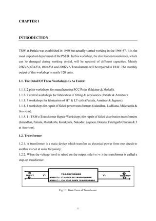
  • 1. 1 CHAPTER 1 INTRODUCTION TRW at Patiala was established in 1960 but actually started working in the 1966-67. It is the most important department of the PSEB. In this workshop, the distribution transformer, which can be damaged during working period, will be repaired of different capacities. Mainly 25KVA, 63KVA, 100KVA and 200KVA Transformers will be repaired in TRW. The monthly output of this workshop is nearly 120 units. 1.1. The Detail Of These Workshops Is As Under: 1.1.1. 2 pilot workshops for manufacturing PCC Poles (Muktsar & Mohali). 1.1.2. 2 central workshops for fabrication of fitting & accessories (Patiala & Amritsar). 1.1.3. 3 workshops for fabrication of HT & LT coils (Patiala, Amritsar & Jagraon). 1.1.4. 4 workshops for repair of failed power transformers (Jalandhar, Ludhiana, Malerkotla & Amritsar). 1.1.5. 11 TRWs (Transformer Repair Workshops) for repair of failed distribution transformers (Jalandhar, Patiala, Malerkotla, Kotakpura, Nakodar, Jagraon, Doraha, Fatehgarh Churian & 3 at Amritsar). 1.2. Transformer 1.2.1. A transformer is a static device which transfers ac electrical power from one circuit to another circuit at same frequency. 1.2.2. When the voltage level is raised on the output side (v2>v1) the transformer is called a step-up transformer. Fig.1.1. Basic Form of Transformer
  • 2. 2 1.2.3. When the voltage level is lowered on the output side (v1>v2) the transformer is called a step down transformer. 1.2.4. The winding to which supply is connected is called a primary winding and to winding to which a load is connected is called a secondary winding. 1.3. Working Principal The basic principle of transformer is Electromagnetic Induction. When a.c. supply of voltage ‘Vp’ is connected to primary winding, an alternating flux is set up in the core. This alternating flux when links with the secondary winding an e.m.f. is induced in it called mutually induced e.m.f. The direction of this induced e.m.f. is opposite to the applied voltage ‘Vp’, according to Lenz’s law. The same alternating flux also links with primary winding and produces self- induced e.m.f. ‘Ep’. This induced e.m.f. ‘Ep’ also acts in opposite direction to the applied voltage ‘Vp’ according to Lenz’s law. Although, there is no electrical connection between primary and secondary winding, but electrical power is transferred from primary circuit to secondary circuit through mutual flux. 1.4. Necessity In our country usually electrical power is generated at 11 kV. From economic reasons ac power is transmitted at very high voltages (220kV or 400 kV ) over long distances, therefore a step- up transformer is applied at the generating station .then to feed the different areas, voltages are stepped down to different levels by transformer at various substations. Ultimately for utilization of electrical power the voltage is stepped down to 400/230v for safety reasons thus transformer plays an important role in the power system. Here in the T.R.W, we are dealing with distribution transformers only .the major difference between power and distribution transformers is given below: 1.5. Difference Between Power And Distribution Transformers 1.5.1. Power Transformers: these transformers are used to step-up the voltage at the generating station for transmission purposes and to step down the voltage at receiving stations these transformers are of large sizes( generally above 500 kVA ) these transformers are usually operate at high average load, which would cause continuously heavy copper loss, thus affecting their efficiency. To have minimum losses during 24 hours, such transformers are designed with low copper losses.
  • 3. 3 1.5.2. Distribution Transformer: These transformers are installed at the distribution substation to step down the voltage .these transformers are continuously energized causing the iron losses for all the 24 hours, when generally the load fluctuates from no-load to full-load during this period .to obtain high efficiency such transformers are designed with low iron losses. Fig.1.2. Distribution Transformer Fig.1.3. Power Transformer
  • 4. 4 CHAPTER 2 CONSTRUCTION 2.1. Three Phase Transformer: In core type three phase transformer the core has three limbs of equal area of cross section. Three limbs are joined by two horizontal members called yoke .the area of cross-section of all the limbs and yoke is the same since at every instant magnitude of flux setup in each part is the same. The core consists of laminations of silicon steel material having oxide film coating on both the sides of insulation. The lamination are usually of “E” and “I” shape and are staggered alternately. These type of transformers are usually wound with circular cylindrical coils the low voltage winding is wound nearer the core and high voltage (H.V.) winding is wound over low voltage winding. Insulation is always provided between the core and low voltage windings and between low voltage winding and high voltage winding. Here TRW we are dealing with “DY 11” 3 phase transformers connected in GROUP 4 (plus 30⁰ phase displacement) that mean the high voltage winding is connected in delta and low voltage winding is connected in star and that the low voltage line pharos leads the corresponding high voltage line pharos by 30⁰. As the distribution transformer step-downs to 11kV/400v, the high voltage winding (or primary winding in this case) is connected in delta that mean that all the six out coming terminals are connected in such Fig.2.1. Core Type Transformer
  • 5. 5 a manner so as to form a delta connection similarly the low voltage winding (or secondary winding in this case) is connected in star so as to obtain a neutral point or wire that means that all the six out coming terminals are connected in such manner so as to obtain a common neutral point. 1. H.T bush terminal 11. Drain off point 2. H.T bush insulator 12. Transformer core 3. H.T terminal lead 13. L.T winding 4. L.T bush /terminal 14. H.T winding 5. L.T bush insulator 15. Cooling tubes 6. L.T terminal lead 16. Lifting hook 7. Conservator tank 17. Oil level indicator 8. Breather 18. Main tank cover 9. Silica gel (filled in) 19. Base frame 10. Oil filling point 20. Separator sheet Fig.2.2. Cut-Off Pictorial View With Parts Description
  • 6. 6 2.1.1. Core: The transformer core is made up of silicon steel or sheet steel with 4% silicon. In addition to this the sheets are laminated and are coated with an oxide layer to reduce the iron losses. The thickness of the lamination is 0.35 to 0.5 mm. The purpose of the core is to provide a magnetic path of low reluctance between the two windings so that whenever one winding is exited, the flux established by the winding will link fully with the other winding without any appreciable leakage. The permeability of the material used for the core must have a high value (µr >1000), since the reluctance of the magnetic path is inversely proportional to µ. 2.1.2. Windings: The winding which receives the electrical energy is called the primary winding and the winding which delivers the electrical energy is known as secondary winding. Earlier the windings are made up of high grade copper but due to high cost of copper, aluminum conductors are used nowadays. The windings are provided with insulation such that any one turn will not come into contact with the other turns. Bare aluminum wire are also given enamel coating in addition to the inter turn insulation .double layer cotton insulation is generally used. Pressboard or paper insulation is also used for supporting the windings. 2.1.3. Transformer Tank And Tank Cover: The tank and the tank cover are manufactured of hot-rolled, unalloyed steel sheet and profile balks. Fine granular steel is used in transformers for low ambient temperatures. Areas where strong eddy currents can be generated due to high currents, and where ordinary hot-rolled steel can become too warm, are made of non-magnetic (austenite) steel. The tank has lifting lugs for lifting the transformer (fully-equipped transformer including oil) and at least four jacking points the lower part if the tank for lifting by hydraulic jacks. For transport wheels there are fixing points at the bottom of the tank. The tank is provided with at least two ear thing lugs made of stainless steel. The connecting flanges of the coolers and the flanges for filling, draining, filtering and sampling valves are welded to the tank. Also the fixing brackets of cooler fans are welded to the tank. Usually the support of the oil conservator is fastened to the tank too. The transformer cover is fixed to the tank usually by means of a bolt joint using oil resistant rubber cork as the gasket. A gasket made of special rubber can also be used. The cover can also be fixed to the tank by welding. The welded seams are tighter and more reliable than bolted ones. They can be quite easily opened and rewelded. The transformer cover is constructed so that no water pockets or other water collector points are formed. An air pipe is connected to the gas relay from all the turrets, flanges etc. where it is possible for gas pockets to develop.
  • 7. 7 2.1.4. Conservator Tank: When a transformer is oil filled, the oil in the tank is subjected to heat and thus will naturally expand and contract due to the variation in load current and is also subjected to seasonal variation. The conservator tank provides the means for the oil to settle down by expanding under heavy loads. Without such a tank very high pressure tank will be developed inside it which could lead to bursting of transformer tank. 2.1.5. Bushes: Transformer Bushings are specially designed electrical terminals for taking out winding ends (leads) through the openings provided on the top cover or wall of the of transformer tank and connecting to the incoming and outgoing lines. The purpose of the bushings is to provide proper insulation for the output leads to be taken out from the transformer tank. Bushings used are generally of two types: 2.5.1. Porcelain type which are used for voltage rating of up to 33kV. 2.5.2. Condenser type and oil filled type which are used for voltage rating higher than 33kV. 2.1.6. Diaphragm: it consist of a long tube having a hard paper at one end. Whenever there is sudden expansion of oil and evolution of gases, the paper blows out thus preventing the damaging and bursting of transformer tank and gives a path to flow of those gases. Fig.2.3. H.T. Bushings
  • 8. 8 1. Core 9. LT Phase Leads 2. Press Pan Paper 10. Fiber Glass Sleeves 3. LT winding 11. Bakelite tubes 4. Drum (Press Board Sheet) 12. H.T. Delta Point 5. HT winding 13. Fabrication Angle 6. Star Points 14. Separator-Gutties 7. Thimbles (LT) 15. Press board Sheet (2mm) 8. HT Phase Leads 16. Fabrication Nut Bolt Fig.2.4. Three- Phase Distribution Transformer Core
  • 9. 9 2.1.7. Breather: Transformer oil should not be exposed directly to the atmosphere because it may absorb moisture and dust from the environment and may lose its electrical properties in a very short time. To avoid this from happening, a breather is provided which contains the silica gel. The breather completely prevents the moisture and dust from coming into contact with the oil in the conservator tank when it expands or contracts, depending on the variations in the load during expansion and contraction of oil breather containing silica gel helps in outgoing and in taking of air present in the conservator tank. Silica gel absorbs the moisture content present in the air. Silica gel in normal condition is blue in color whereas when it absorbs moisture it turns to pink and needs to be changed. 2.1.8. Radiators: Radiators are the small pipes taken out from the transformer tank through which transformer oil can easily flow. Thus radiator provides an easy path for the circulation of transformer oil and helps in cooling of oil. Fig.2.5. Radiator
  • 10. 10 CHAPTER 3 CONNECTION 3.1 Three Phase Transformer Connections The low voltage winding and high voltage winding can be connected in either star (y) or delta (∆) to form a complete unit. The reason for choosing a Y or Δ configuration for transformer winding connections is that: Y connections provide the opportunity for multiple voltages, while Δ connections enjoy a higher level of reliability (if one winding fails open, the other two can still maintain full line voltages to the load). 3.1.1. Star-Connection: In a star connection we can take out a neural point from the common point. The line voltage between any two phases is same but due to the presence of neutral we can get the per phase voltage which is 1/√3 times the line voltage. Therefore this system is highly used for distribution purposes. Fig.3.1. Distribution Transformer Connections Fig.3.2. Star Connection
  • 11. 11 3.1.2. Delta-Connection: The delta system can be illustrated by a simple triangle. Only one voltage is available between any two wires in a delta system. The voltage would be the same between any two wires. 3.2. Types Of Three Phase Transformers Are: 3.2.1. Star-Star (Y-Y) – high voltage and low voltage winding both are connected in star. 3.2.2. Delta-Delta (D-D) - high voltage and low voltage winding both are connected in delta. 3.2.3. Delta-Star (D-Y) - high voltage winding is connected in delta and low voltage winding is connected in star. 3.2.4. Star-Delta (Y-D) -high voltage winding is connected in star and low voltage winding is connected in delta. 3.3. Some Important Notations: 3.3.1. Transformation Ratio: the ratio of secondary voltage to primary voltage is called voltage transformation ratio of the transformer denoted by “k”. Here at T.R.W the transformation ratio is maintained at 44 ± 1%. K=V2/V1 = N2/N1 Since V2 ∝ 𝑁2 and E1 ∝ 𝑁1 3.3.2. Turn Ratio -: the ratio of primary to secondary turns is called turn ratio =𝑛1/𝑛2 Fig.3.3. Delta Connection
  • 12. 12 CHAPTER 4 LOSSES IN THE TRANSFORMER 4.1. Core or Iron Losses: when ac supply is given to the primary winding of a transformer an alternating flux is setup in the core, therefore hysteresis and eddy current losses occur in the magnetic core. Type of core losses are: 4.1.1. Hysteresis Loss: when the magnetic material is subjected to reversal of flux, power is required for the continuous reversal of molecular magnets ,this power is dissipated in the form of heat and is known as hysteresis loss( 𝑷h=𝑲h 𝑽𝒇 𝑩1.6) This loss can be minimized by using silicon steel material for the construction of core. 4.1.2. Eddy Current Loss: since flux in the core of a transformer is alternating, it links with the magnetic material of the core itself also, this induces an emf in the core and circulates eddy currents. Power is required to maintain these eddy currents (𝑷e= 𝑲e 𝑽𝒇2 𝑻2 𝑩2), this power is dissipated in the form of heat and is known as eddy current losses. This loss can be minimized by making the core of thin laminations. 4.2. Apparent Losses: when the transformer is on no-load, a small current called exiting current flows through the winding of transformer having very small resistance. Therefore this current results in I2 R loss which is almost negligible. The flux setup in the core of the transformer remains constant from no load to full load. Hence, iron loss are independent of the load and are known as constant losses. 4.3. Copper Losses: copper losses occur in both the primary and secondary windings due to their ohmic resistances .If I1, I2 are the primary and secondary currents and R1, R2 are the primary and secondary resistances respectively. Then total copper losses = I1 2R1+I2 2R2 4.4. Stray Losses: Some of the leakage flux present in a transformer induce eddy currents in conductors, tanks, channels, bolts etc. and these eddy currents give rise to stray losses. However, these losses are very small & neglected. The current and hence flux in the primary and secondary winding vary according to the load, therefore these losses vary according to the load and are known as variable losses.
  • 13. 13 CHAPTER 5 IMPORTANT POINTS 5.1. The transformer core is made up by laminated silicon steel stampings in order to avoid hysteresis and eddy current losses. Theses laminations are also self-insulated by using an oxide layer or varnish and are hold together by yoke. 5.2. The core is made in “E” and “I” configuration. 5.3. In order to reduce air gap and to provide insulation, all the stampings are tightly binded by cotton tape. 5.4. As high voltage winding is connected directly across high voltage, it is made up of thin insulated wire .As the power in the system remains same the wire of low tension side is made up of thick wire in order to compensate with increase in current. There are total 4 out coming terminals from the low voltage side thus providing flexibility to the system (for a 100 kVA transformer). 5.5. The high voltage winding or primary winding in this case is connected in delta that means that all the six terminals coming out(2 terminals per limb) is connected in delta and the low voltage winding is connected across distribution end therefore the out coming terminals are connected in star so as to get a neutral point. Fig.5.1. ‘E’ And ‘I’ Shaped Steel Lamination
  • 14. 14 5.6. The winding is not directly placed on the core; rather insulation is used before placing the coils. 5.7. The core is first covered with paper, then the coil is placed over it which there self is insulated by double insulation paper .a space of 8 mm is left between last coil and core and a space of 2 mm is left between each coil so as to provide direct contact with core and to provide insulation between the core and circulation of oil between different coils. 5.8. Core is always kept at earth potential. 5.9. In a distribution transformer the neutral is always on the right side. 5.10. In order to reduce size of transformer the high voltage winding is always placed over low voltage winding. 5.11. From economical point of view single high tension coil is not used, as it is directly connected across the high voltage and in case of any fault all of the coil is damaged if single coil is used therefore no. of coils per limb (2 coils/limb, 3 coils/limb etc.) connected in series is used as high tension winding .The first one is the a single coil of high tension winding whereas the second one is the low voltage winding. Fig. 5.2. Paper Used To Cover the Core of Transformer Fig. 5.3. High Voltage Winding Fig.5.4. Low Voltage Winding
  • 15. 15 CHAPTER 6 TRANSFORMER TESTS 6.1. T.T.R. (Transformer Turn Ratio) Test: This test is done to calculate the transformation ratio of the transformer performed by using a T.T.R set. This set consist of a hand driven generator having 4 cables of red ,yellow ,blue and black in color. The turn ratio is maintained between 43.560 and 44.440. The T.T.R value should be in the permissible range. If not, there is a need to increase or decrease the air gap and to provide sum insulation. Generally pressboard sheet is used to provide insulation for this case. T.T.R value of a 63 kVA transformer is given below: R- Y = 44.000 Y-B = 44.065 B-R = 44.170 6.2. Insulation Resistance Test: I.R test is done with the help of MEGGER. It consists of a generator, two out coming terminals, a selector switch and a deflector. Three type of I.R tests are carried out by using megger. 6.2.1. H.T. To Earth Test: One of the megger terminal is connected to any H.T bush and the other one is connected to the core. When the generator is started the voltage induced in the system is the product of the resistance shown in deflection meter and the number given Fig.6.1. Transformer Turn Ratio Test Setup
  • 16. 16 to the selector switch is in this that way we can get the maximum value of resistance produced in the system. Insulation resistance is given by the product of resistance shown by the deflector and the no. pointing by the knob of the selecting switch. If I.R. value is low we can say that there is presence of some moisture in the transformer. Therefore the transformer is kept in the oven to remove the moisture. For example- let the reading in the meter is 500 mega ohm and the selector switch is pointed to no.5, then we can say than the maximum resistance of the system is 500 mega ohm at 2500 volts (5x500=2500). H.T to earth Insulation Resistance value for a 63 kVA transformer is 1200 mega ohm. 6.2.2. L.T. To Earth Test: One of the cable is connected to bush of L.T and other one to the earth, and the procedure of taking the reading is as above in fig.6.2. L.T to Earth Insulation Resistance value for a 63 kVA transformer = 1280 mega ohm 6.2.3. H.T. To L.T Test: One cable is connected to H.T bush and the other one is connected to L.T bush. H.T to L.T Insulation Resistance value for a 63 kVA transformer = 1350 mega ohm Fig.6.2. H.T. To Earth Test
  • 17. 17 6.3. D.V.D.F Test (Double Voltage Double Frequency Test): This test is performed only on L.T side, H.T side being open. An alternator is used to produce a voltage of 840 volts at almost 100Hz.this test is used to check the insulation of L.T bushes and is done for one minute only, otherwise the bush will get damaged. This test is also used to check the air gap in L.T winding. A semi-automatic star- delta started is used to start the alternator and the field exciter is used to excite the field winding of the alternator. Fig.6.3. D.V.D.F Test Setup Fig.6.4. Star Delta Switching System Fig.6.5. Name Plate of Star-Delta Starter
  • 18. 18 6.4. L.T Test: This test is performed to check the insulation resistance of the L.T winding and if the resistance value is low , sparking produced, however to perform this test a voltage of 3kV is given to the L.T side keeping the H.T side short-circuited and connected to the earth. When the voltage is applied across L.T, a voltage of about 25 times that of L.T side is induced at H.T side due to mutual induction which is nearly equal to 75 kV. Generally a variac is used to change the voltage. Fig.6.6. L.T. Test Fig.6.7. H.T. And L.T. Test Setup
  • 19. 19 6.5. H.T Test: Its purpose is same as that of L.T test the only difference is that a high voltage of 28 kV is applied on H.T bush keeping L.T. bushes open and neutral is earthed. 6.6 Loss Test: Two type of tests are performed to determine the losses of the transformer .these are open circuit test and short circuit test. 6.6.1. Open-Circuit OR No Load Test: This test is carried out to determine the no load loss or core loss or iron loss and no load current which is helpful in finding the no-load parameters. This test is usually carried out on the low voltage side of the transformer i.e. a wattmeter, an ammeter and a voltmeter is connected in the low voltage winding. The winding is connected to normal rated voltage as given on the name plate of the transformer. The other H.T is kept open .since the H.T is open circuited, the current drawn by the L.T is called no load current measured by the ammeter .the value of no-load current is very small usually 2 to 10% of the rated full-load current. Thus the cupper losses in the L.T are negligibly small and no copper loss occurs in the H.T as it is open. 6.6.2. Short Circuit Test: This test is carried out to determine the copper losses on full load. This test is carried out on the high voltage side of the transformer i.e. a wattmeter, a voltmeter and an ammeter are connected on high voltage winding. The other winding is then short- circuited by a thick strip .a low voltage at normal frequency is applied across high voltage winding so that full load current flows in both the windings .if high voltage is applied, an excessive current will flow in both the windings which may damage them. Fig.6.8. H.T. Test
  • 20. 20 Since a low voltage (usually 5 to 10% of normal rated voltage) is applied to the transformer winding. Therefore, the flux setup in the core is very small about 1/30 to 1/8th of normal flux .the iron losses are negligibly small due to low value of flux as these losses are approximately proportional to the square of the flux. Hence wattmeter only represents the copper losses in the transformer windings for all practical purposes. Experiment Open circuit test on a 63 kVA transformer Supply voltage=433 V Ammeter reading =1 A Difference between the wattmeter reading= = W1- W2 = 90 - 60=30 watts Resultant wattage x C.T ratio=30 x 5=150 watts It is required that the no-load losses should be less than 170.5 watts Short circuit test on 63 kVA transformer Input current= 3.31 A Difference between wattmeter reading = W1- W2= 230-30=200 watts Resultant wattage x C.T ratio=200x5 = 1000 watts These are the losses at 28⁰ C .to calculate the losses at 75⁰ C i.e. maximum working voltage, we have modified a formula Losses at 20⁰C x (300/225+present temperature) =1000x1.185=1185 watts. Fig.6.9. Loss Test Setup
  • 21. 21 CHAPTER 7 EFFICIENCY OF A TRANSFORMER The commercial efficiency is given by the ratio of output power to input power: Commercial efficiency = ƞ = 𝒐𝒖𝒕𝒑𝒖𝒕 𝒑𝒐𝒘𝒆𝒓/𝒊𝒏𝒑𝒖𝒕 𝒑𝒐𝒘𝒆𝒓 The load on certain transformers fluctuates throughout the day. The distribution transformers are energized for 24 hours, but they delivers very light loads for major portion of the day. Thus iron losses occur for whole day but copper losses occurs only when the transformer are loaded. Hence the performance of such transformers cannot be judged by the commercial efficiency, but it can be judged by all-day-efficiency also known as operational efficiency or energy efficiency which is computed on the basis of energy consumed during a period of 24 hours. The all-day-efficiency is defined as the ratio of output in kWh to the input in kWh of a transformer over 24 hours. All-day efficiency = ƞ all-day =𝒐𝒖𝒕𝒑𝒖𝒕 𝒊𝒏 𝒌𝑾𝑯/𝒊𝒏𝒑𝒖𝒕 𝒊𝒏 𝒌𝑾𝑯 (for 24 hours)
  • 22. 22 CHAPTER 8 HEATING OF TRANFORMER 8.1 The distribution of voltage is not uniform along the winding the winding with 80% of the voltage appearing across the first 10% of the turns from the line end .for large power and distribution transformer, an oil filled tank is necessary for providing cooling for the windings and core. There are major two type of losses: 8.1.1. Core losses 8.1.2. Copper losses 8.2. Heat is generated because of energy loss and is roughly proportional to the volume of the material in which the losses occur, whereas the heat dissipation is proportional to the surface area of the same material and the tank. 8.3. This ratio must approach unity to limit the temperature rise. To achieve this, the surface area of the tank is made corrugated. To improve this further, radiators are also used. Radiators not only increase the surface area but also provide the path for the circulation of the cooling fluid i.e. transformer oil.
  • 23. 23 Fig.8.1. Columbia Transformer Oil Drum Name Plate Fig.8.2. Savita Transformer Oil Drum Name Plate Fig.8.3. Transformer Oil Drum
  • 24. 24 CHAPTER 9 TRANFORMER OIL Transformer oil is a Mineral Oil obtained by fractional distillation of Crude Petroleum. The oil is used only in the oil-cooled transformer. The oil not only carries the heat produced due to losses in the transformer, by convection from the windings and core to the transformer tank, but also has even more important function of insulation. When transformer delivers power, heat is produced due to the iron and copper losses in the transformer. This heat must be dissipated effectively otherwise the temperature of the winding will increase. The rise in temperature further increases the losses. Thus, the efficiency of the transformer will decrease. As there is no rotating part in the transformer it is difficult to cool down the transformer as compared to rotating machines. Various methods to cool down the transformers of different rating. Fig.9.1. Oven Used To Remove The Moisture Content From Transformer
  • 25. 25 9.1. The Common Methods Of Cooling Are: 9.1.1. Air natural cooling 9.1.2. Oil immersed natural cooling 9.1.3. Oil immersed forced oil circulation natural cooling 9.1.4. Oil immersed forced oil circulation with the air blast cooling 9.1.5. Oil is immersed forced oil circulation with water cooling etc. 9.2. Good Transformer Oil Must Possess The Following Properties: 9.2.1. High dielectric strength 9.2.5. Low viscosity 9.2.2. High temperature coefficient of expansion 9.2.6. Thermally stable 9.2.3. Chemically stable 9.2.7. Low sludge formation 9.2.4. Low moisture content 9.3. T.R.W. Purchase Transformer Oil From Two Companies 9.3.1. Columbia petro-chem pvt.ltd. 9.3.2. Savita oil technology limited
  • 26. 26 CHAPTER 10 INTERNAL CLEARANCE IN THE TRANSFORMER TANK Table 10.1. Internal Clearance In The Transformer Tank S. No. TYPE Clearance 9.1 Between HV & LV 10mm 9.2. Between HV winding & Tank wall 9.2.1 Non Bushing Sides 25 mm 9.2.2 Bushing Sides 40 mm 9.2.3 Between Sections of HV winding 06 mm 9.2.4 Between HV winding 10 mm 9.2.5 Between HV & Yoke 25 mm 9.2.6 Between LV & Yoke 10 mm 9.2.7 Between Yoke & Inside of Tank Top Cover 100 mm 9.2.8 Between Yoke & Tank Bottom 40 mm 9.2.9. Between LV & Core 03 mm 9.3. Electrical Clearance 9.3.1 Between Phase to Phase 255 mm 9.3.2 Between Phase to Earth 205 mm
  • 27. 27 CHAPTER 11 VISIT TO COIL FABRICATION WORKSHOP This workshop is a site where H.T and L.T coils of various transformers ranging from 25kVA to 300kVA are manufactured and supplied to T.R.W. coils of various diameters and cross sectional area are configured here. Their specifications are as follows. Table 11.1. Data of Transformer Winding S.NO. TYPE H.T. L.T. 1. 25 kVA 0.8 mm 6 x 3.75 5.60 x 3.55 5.65 x 3.25 2. 63 kVA 1.3 mm 7 x 4 3. 100 kVA 1.6 mm 10 x 4.40 10.65 x 4.35 4. 200 kVA 2.03 mm 2.36 mm 8.35 x 5.15 5. 300 kVA 2.65 mm 7 x 4 As H.T has many no. of turns therefore it is measured in mm and given in diameter whereas L.T being large in cross-sectional area given in width and height for example “10 x 4.40” denotes 10mm width and 4.40mm height. All the coils made here is double paper covered (D.P.C).
  • 28. 28 CHAPTER 12 MACHINES USED FOR WINDING Fig.12.1. H.T. Winding Machine Fig.12.2. L.T. Winding Machine
  • 29. 29 CHAPTER 13 PAPER INSULATION Various insulating papers are used to insulate the coil and also, insulation is provide after every set of winding. Various insulating paper used: 10.1. Press Pan Paper – This paper is used as the base of H.T that is H.T is wound over this. The H.T. wire is self-insulated with double paper cover.it is measured in mil and is 7.5 mil in thickness. 10.2. Pressboard Sheets – This sheet is used as the base of L.T and have considerably high thickness than that of press board paper. 10.3. Craft Paper- This paper is used to insulate the wires after every set of windings. It has the thickness in between press pan and press board sheet. All the three insulating materials are tested for 22kV Fig.13.1. Press Board Sheet Cutting Machine
  • 30. 30 CHAPTER 14 OIL TEST LABORATORY Various tests are performed in here to check the quality of oil, whether it is good for use or not. Following tests are performed here. Table 14.1. Oil Test Report Test Unit Requires value Break down voltage kV 30 kV min Specific resistance 1. at 27⁰ C 2. at 90⁰ C Ohm-cm 900 x 1012 min 35 x 1012 min Water content ppm 50 ppm max Presence of oxidation inhibitor Should not be present Pour point ⁰ C -6⁰ max Electric strength kV 50kV min Neutralization value (total acidity) mg KOH/gm. 0.055 max Interfacial tension N/m 0.030 min Flash point ⁰ C 140⁰ C min Sediment or sludge Absent
  • 31. 31 CHAPTER 15 NAME PLATE OF A TRANSFORMER Below is the name plate of a 100kVA transformer .different transformer of different rating and manufactures may have different name plate specifications. Table 15.1. Name Plate Of Transformer Three Phase Transformer Standard Is-2026/1977 T/F Sr. No 32017 kVA 100 Type Of Cooling ONAN Volts HV 11000 Frequency 50 Hz No Load LV 433 Impedance Volts 4.50% Ampere HV 5.25 Vector Group Dyn11 Ampere LV 133.33 Core And Winding (Kg) 322.5 H.V Three - ∆ Mass Of Oil (Kg) 168 L.V Three - Ỵ Total Weight(Kg) 689.5 Load Loss At 75⁰ C 1705 Vol. Of Oil (Liter) 203 No Load Loss 208 Temp. Rise Oil 35⁰C Date Of Inspection Year Of Manufacture Month & Year Of Mfg. 8/2003 Customer Punjab State Electricity Board Order No. H-11623/Q-3803/Po(T) Date 02-06-2005 Date Of Damage With In Warranty Date Of Lifting By The Firm Date Of Repair Nucon Switchgears(P) Ltd.
  • 32. 32 CHAPTER 16 CONCLUSION Let say transformer gets damaged due to any fault it comes to transformer repair workshop (TRW). Then transformer is firstly dismantled and only the core is left. Afterwards, we replace the old cotton tape with fresh one. Then we put L.T. winding over the core. Then we cover the L.T. winding by press board paper. Then we put H.T. winding over the insulated L.T. winding. As H.T. consists of many coils, we put the coil in alternatively, one is clockwise and next is anti-clockwise. Then we put thick sheet of press board cover above windings. Then we fit ‘I’ shaped stamping into ‘E’ shaped stamping. Then we make connection of the transformer’s windings as per requirements. Afterwards we keep the core in the oven to remove moisture content. After the whole setup is placed into the tank and fill the tank with fresh oil. Then connect the winding to the outer terminals. Then we perform certain test to ensure that transformer is ready for operations. If the result of the tests are OK then transformer is ready to operate.
  • 33. 33 CHAPTER 17 REFERENCES 1. https://en.wikipedia.org 2. Bimbhra, P.S., ‘Electrical Machines’, Khanna Publishers