![ Printer/scanner [if
attached]](data:image/gif;base64,R0lGODlhAQABAIAAAAAAAP///yH5BAEAAAAALAAAAAABAAEAAAIBRAA7)
Recommended
More Related Content
What's hot
What's hot (20)
Similar to Parts of computer system (how to assemble and disassemble the computer)
Similar to Parts of computer system (how to assemble and disassemble the computer) (20)
Recently uploaded
Recently uploaded (20)
Parts of computer system (how to assemble and disassemble the computer)
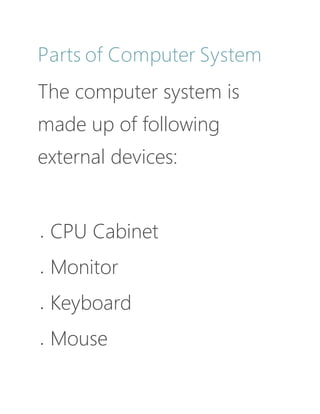
- 1. Parts of Computer System The computer system is made up of following external devices: CPU Cabinet Monitor Keyboard Mouse
- 3. switch off the power supply and detach power cable | Source
- 4. remove the CPU cabinet cover
- 5. detach internal cables | Source
- 7. remove CD/DVD drives | Source
- 8. remove Hard Disk Drive | Source
- 9. remove RAM | Source
- 10. Disassembling the computer system Detach the power cable: The disassembling of the computer system starts with externally connected device detachment. Make sure the computer system is turned off, if not then successfully shut down the system and then start detaching the external devices from the computer system. It includes removing the power cable from electricity switchboard, then remove the cable from SMPS (switch mode power supply) from the back of the CPU Cabinet. Do not start the disassembling without detaching the power cable from the computer system. Now remove the remaining
- 11. external devices like keyboard, mouse, monitor, printer or scanner from the back of CPU cabinet. Remove the Cover: The standard way of removing tower cases used to be to undo the screws on the back of the case, slide the cover back about an inch and lift it off. The screwdrivers as per the type of screw are required to do the task. Remove the adapter cards: Make sure if the card has any cables or wires that might be attached and decide if it would be easier to remove them before or after you remove the card. Remove the screw if any, that holds the card in place. Grab the card by its edges, front and back,
- 12. and gently rock it lengthwise to release it. Remove the drives: Removing drives is easier. There can be possibly three types of drives present in your computer system, Hard disk drive, CD/DVD/Blue-ray drives, floppy disk drives (almost absolute now a day). They usually have a power connector and a data cable attached from the device to a controller card or a connector on the motherboard. CD/DVD/Blue Ray drive may have an analog cable connected to the sound card for direct audio output. The power may be attached using one of two connectors, a Molex connector or a Berg connector for
- 13. the drive. The Molex connector may require to be wiggled slightly from side to side and apply gentle pressure outwards. The Berg connector may just pull out or it may have a small tab which has to be lifted with a screwdriver. Now Pull data cables off from the drive as well as motherboard connector. The hard disk drive and CD/DVD drives have two types of data cables. IDE and SATA cables. The IDE cables need better care while being removed as it may cause the damage to drive connector pins. Gently wiggle the cable sideways and remove it. The SATA cables can be removed easily by pressing the tab and pulling the connector straight back.
- 14. Now remove the screws and slide the drive out the back of the bay. Remove the memory module: Memory modules are mounted on the motherboard as the chips that can be damaged by manual force if applied improperly. Be careful and handle the chip only by the edges. SIMMs and DIMMs are removed in a different way: SIMM - gently push back the metal tabs while holding the SIMM chips in the socket. Tilt the SIMM chip away from the tabs until a 45% angle. It will now lift out of the socket. Put SIMM in a safe place. DIMM- There are plastic tabs on the end of the DIMM sockets. Press the tabs down and away from the
- 15. socket. The DIMM will lift slightly. Now grab it by the edges and place it safely. Do not let the chips get dust at all.
- 16. remove processor
- 17. remove the motherboard | Source
- 18. Remove the power supply: The power supply is attached into tower cabinet at the top back end of the tower. Make sure the power connector is detached from the switchboard. Start removing the power connector connected to motherboard including CPU fan power connector,
- 19. cabinet fan, the front panel of cabinet power buttons and all the remaining drives if not detached yet. Now remove the screws of SMPS from the back of the cabinet and the SMPS can be detached from the tower cabinet. Remove the motherboard:
- 20. Before removing all the connectors from the motherboard, make sure u memorize the connectors for assembling the computer if required, as that may require connecting the connectors at its place. Remove the screws from the back of the motherboard and you will be able to detach it from the
- 21. cabinet. Now remove the CPU fan from the motherboard. The heat sink will be visible now which can be removed by the pulling the tab upward. Finally, the processor is visible now, which can be removed by the plastic tab which can be pulled back one stretching it side way.
- 22. Assembling the computer system The assembling of the computer system is exactly the opposite of disassembling operation. Before starting assembling the computer system, make sure you have the screws and a screwdriver for those. The first step for assembling the
- 23. computer system starts with mounting the processor on the processor socket of the motherboard. To mount the process, you don't need to apply any force. The special ZIF (zero insertion force) sockets are usually used to prevent any damage to the processor pins. Once the processor is
- 24. mounted, the heat sink will be attached on top of the processor. The CPU fan is also attached on top of the heat sink. Now the motherboard is to be fixed vertically in the tower case and the screws are fixed from behind of the motherboard.
- 25. Now line up the power supply at the top back end of the cabinet and screw it. The power connectors for motherboard power supply and CPU fan power supply are to be connected. If the cabinet cooling FAN is required then it is to be screwed at the back end grill of the cabinet and its power connector is to
- 26. be connected from SMPS. Install the CD/DVD drives at the top front end of the cabinet and screw it. Install the Hard disk drive and floppy disk drive below CD/DVD drive and screw it. Make sure once screwed there is no vibration in either of the CD/DVD, Hard
- 27. disk or Floppy disk drives. Now select the appropriate data cable and connect one end of the cable to its drive socket and another end at its appropriate connector on the motherboard. For SATA hard disk drive or CD/DVD drives use SATA cable and its power cable, else use IDE data
- 28. cable. Do the proper jumper settings as per the usage requirement. It is time now to mount the memory modules on the motherboard by aligning the RAM to its socket on the motherboard and press it downward. Make sure the side tab are fixed into the RAM notch. If not, you
- 29. may still have to press a bit. Install the internal cards to its socket and attach the cables or power cable to it. The selection of right socket or slot is required as per the type of socket. Cover the tower by placing it and pressing towards front side and screw it.
- 30. Connect the external devices with CPU at its appropriate socket. It includes mouse and keyboard at PS2 or USB connectors. Monitor at the video output socket. Connect the power cable to the back of tower in SMPS. Plug in the power cable to the electric board.
- 31. This article is accurate and true to the best of the author’s knowledge. Content is for informational or entertainment purposes only and does not substitute for personal counsel or professional advice in business, financial, legal,