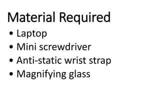
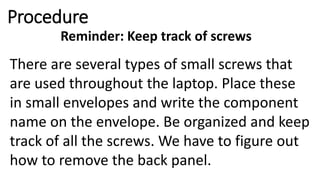
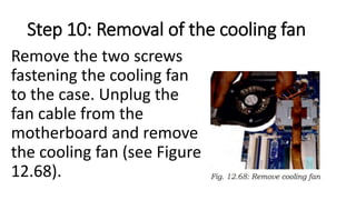
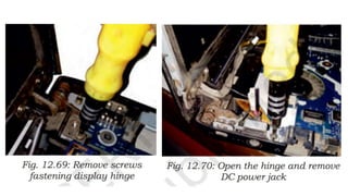
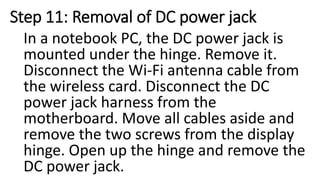
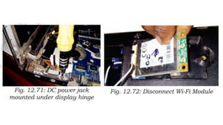
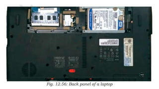
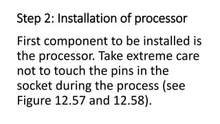
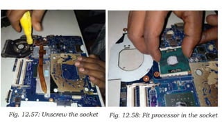
Assembling and Disassembling of Laptop
Material Required
• Laptop
• Mini screwdriver
• Anti-static wrist strap
• Magnifying glass
Disassembly of Laptop
Steps is depends on the Laptop Model.
Procedure
Reminder: Keep track of screws
There are several types of small screws that are used throughout the laptop. Place these in small envelopes and write the component name on the envelope. Be organized and keep track of all the screws. We have to figure out how to remove the back panel.
Step 1: Removal of battery
Start the disassembly process by removing the battery (see Figure 12.59). Remove one screw securing the optical CD/DVD drive. Pull out the optical drive and remove it. Remove all the screws securing the bottom case. There are two screws hidden under the two laptop bottom feet. Remove the bottom screws. Peel off the bottom from the case to access the hidden screws. Remove the hidden screws from both sides of the notebook.
Step 2: Separation of palm rest
Using a plastic case opener, separate the palm rest from the bottom case as shown in Figure 12.60.
Step 3: Removal of bottom case
Turn the notebook upside down and remove the bottom case.
Step 4: Disconnecting the hard drive cable from the motherboard
Step 5: Remove the hard drive
Remove the hard drive assembly from the notebook. If you are going to replace it with another hard drive or SSD, you will have to transfer the mounting bracket and the SATA cable.
Step 6: Removal of RAM
A notebook PC motherboard has two memory slots. Remove both RAM modules if necessary.
Step 7: Disconnection of cable
Remove the one screw fixing the USB LED status board. Disconnect the cable from the motherboard.
Step 8: Removal of USB LED status board
Step 9: Removal of screw fixing the optical CD/ DVD drive connector board
Remove the one screw fixing the optical CD/DVD drive connector board. Disconnect the cable from the motherboard.
Step 10: Removal of the cooling fan
Remove the two screws fastening the cooling fan to the case. Unplug the fan cable from the motherboard and remove the cooling fan (see Figure 12.68).
Step 11: Removal of DC power jack
In a notebook PC, the DC power jack is mounted under the hinge. Remove it. Disconnect the Wi-Fi antenna cable from the wireless card. Disconnect the DC power jack harness from the motherboard. Move all cables aside and remove the two screws from the display hinge. Open up the hinge and remove the DC power jack.
Step 15: Removal of screw securing the board
The power button board is also mounted under the same hinge. Remove the one screw securing the board and unplug the cable from the motherboard.
Step 12: Removal of motherboard
Separate the motherboard from the top case and remove it. The other side of the motherboard is shown in Figure 12.74. In a notebook PCs, the keyboard is permanently attached to the top case with rivets. When the keyboard fails, it is necessary to replace the top case. The touchpad is glued to the top case but the touchpad button board can b
5. Procedure
Reminder: Keep track of screws
There are several types of small screws that
are used throughout the laptop. Place these
in small envelopes and write the component
name on the envelope. Be organized and keep
track of all the screws. We have to figure out
how to remove the back panel.
6. Step 1: Removal of battery
Start the disassembly process by removing the
battery (see Figure 12.59). Remove one screw
securing the optical CD/DVD drive. Pull out the
optical drive and remove it. Remove all the screws
securing the bottom case. There are two screws
hidden under the two laptop bottom feet. Remove
the bottom screws. Peel off the bottom from the
case to access the hidden screws. Remove the
hidden screws from both sides of the notebook.
7.
8. Step 2: Separation of palm rest
Using a plastic case opener,
separate the palm rest from
the bottom case as shown in
Figure 12.60.
9.
10. Step 3: Removal of bottom case
Turn the notebook upside
down and remove the
bottom case.
12. Step 5: Remove the hard drive
Remove the hard drive assembly
from the notebook. If you are going
to replace it with another hard
drive or SSD, you will have to
transfer the mounting bracket and
the SATA cable.
13.
14. Step 6: Removal of RAM
A notebook PC motherboard has
two memory slots. Remove both
RAM modules if necessary.
15. Step 7: Disconnection of cable
Remove the one screw fixing
the USB LED status board.
Disconnect the cable from
the motherboard.
16. Step 8: Removal of USB LED status board
Remove the USB LED status board.
17. Step 9: Removal of screw fixing the optical CD/
DVD drive connector board
Remove the one screw fixing the
optical CD/DVD drive connector
board. Disconnect the cable from
the motherboard.
18. Step 10: Removal of the cooling fan
Remove the two screws
fastening the cooling fan
to the case. Unplug the
fan cable from the
motherboard and remove
the cooling fan (see Figure
12.68).
19.
20. Step 11: Removal of DC power jack
In a notebook PC, the DC power jack is
mounted under the hinge. Remove it.
Disconnect the Wi-Fi antenna cable from
the wireless card. Disconnect the DC
power jack harness from the
motherboard. Move all cables aside and
remove the two screws from the display
hinge. Open up the hinge and remove the
DC power jack.
21.
22. Step 15: Removal of screw securing the board
The power button board is also
mounted under the same hinge.
Remove the one screw securing
the board and unplug the cable
from the motherboard.
23. Step 12: Removal of motherboard
Separate the motherboard from the top case
and remove it. The other side of the
motherboard is shown in Figure 12.74. In a
notebook PCs, the keyboard is permanently
attached to the top case with rivets. When the
keyboard fails, it is necessary to replace the top
case. The touchpad is glued to the top case but
the touchpad button board can be removed.
26. Procedure
Step 1: Keep track of screws
There are several types of small screws that
are used throughout the laptop. Place these
in small envelopes and write the component
name on the envelope. Be organized and keep
track of all the screws. We have to figure out
how to remove the back panel.
27.
28. Step 2: Installation of processor
First component to be installed is
the processor. Take extreme care
not to touch the pins in the
socket during the process (see
Figure 12.57 and 12.58).
29.
30. Step 3: Pop in the video card
First, find the baggie with three larger silver
screws and two small black screws to install the
graphics card. Hold the card at about a 30-
degree angle as you insert its edge connector
into the video-card slot near the center of the
motherboard. Press the card in and downward,
and then use the two small black screws to
secure it in place.
31. Step 4: Set up the drive
The motherboard SATA connectors are along
the front, right edge, and under the lip of the
laptop’s shell. Drop the drive into place and
then carefully use your thumb to push the
drive into the SATA connectors. Now use the
remaining two screws to secure the drive in
place.
32. Step 5: Add memory
To install memory, locate the memory
slots on the motherboard. Align the
notches on the memory module with
the ridge in the slot. Firmly push the
module until the clips on the side of the
slot snap into place.
33. Step 6: Final assembly
Now that all the hardware components are
installed, find the four screws you removed from
the ACE door, slide the door back into place, and
replace the screws. To prepare for power up,
pop in the notebook’s battery pack, connect the
power brick and plug it into a wall outlet. Finally,
open the laptop’s cover with one hand, use your
other hand to press the power button.