Downloaded 342 times


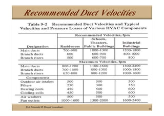


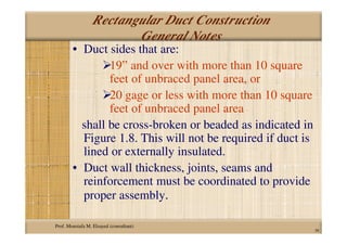

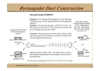


This document discusses duct construction and design. It covers topics such as duct sizing methods, pressure classifications, sealing requirements, recommended velocities, insulation choices, material types, rectangular and round duct construction procedures, joint types, hangers and supports. Tables and diagrams are provided to illustrate duct reinforcement schedules, pressure ratings, seam types, and support spacing. Guidelines are given for controlling costs through aspect ratio optimization and pressure classification.


