
Recommended
More Related Content
What's hot
What's hot (20)
Viewers also liked
Viewers also liked (20)
Similar to Transmitter By MItesh Kumar
Similar to Transmitter By MItesh Kumar (20)
More from Mitesh Kumar
More from Mitesh Kumar (20)
Recently uploaded
Recently uploaded (20)
Transmitter By MItesh Kumar
- 1. BY Mitesh kumar 10300513026 Applied Electronics & instrumentation Engg. Haldia Institute of Technology
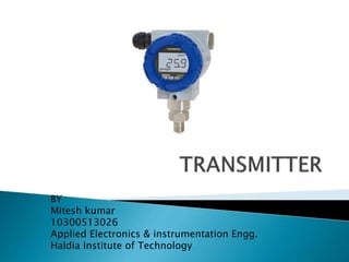
- 2. A transmitter is a transducer - device that associated with a sensor and converts the sensor output(MEASURAND) into a standardized transmission signal. The transmitter, a transducer usually incorporates with various signal conditioning and processing circuits for filtering, amplification/scaling, linearization, isolation etc. of the sensor signal.
- 3. In a process industry, a large number of physical/chemical variables have to measure for the purpose of indication, monitoring, recording and control. Measuring variables : ⇨ Temperature,Pressure,Flow,Level. ⇨ pH, conductivity, humidity, gas/liquid composition, density, viscosity, etc.
- 4. So we have a large number of sensor measuring different variables(order of thousands), which are spread (or distributed) over a large area. In normal practice, bring all the information to a centralized location(control room) in the plant . Total information about the status of the process variables in the entire plant will have in a room though the sensor is located in the field, at the point of measurement. we need a device that converts the sensor output into a suitable form that can be conveyed over large distances, to the control room.
- 5. Transmitter Electronic Analog (4-20 ma/0- 20ma/10-50ma) Smart (digital) (4-20 ma) Field bus compatible (31.25 kbs/s) Pneumatic (3-15 psi/0.2-1 bar)
- 6. A pneumatic transmitter translates the measured value (from sensors) into an air pressure that is transmitted to various receiver devices for indication, recording, alarm, and control. Advantages : • safe and can be used in hazardous atmospheres. • cheap (air costs nothing). ⇨ Pneumatic components are slow in response and incompatible with modern microprocessor based transmitter in terms of their ability to perform sophisticated signal processing and conditioning and their communication capability.
- 8. The detector detects the process variable and the transducer converts this into mechanical movement of flapper of a flapper-nozzle system present in the pneumatic measuring unit. It produces a pneumatic signal in form of nozzle feedback pressure in the range 0.2-1 kg/cm2 and the pneumatic relay amplifies this pneumatic signal and produces an output signal in the range 0.2-1 Kg/cm2. It is then sent to the receiver pressure gauge place in the central control loop through long PVC or SS tube.
- 9. A pneumatic control system operates with air. The signal is transmitted in the form of variable air pressure (often in the range of 0.2 to 1.0 bar (3-15 psi)) that initiates the control action. One of the basic building blocks of a pneumatic control system is the flapper nozzle amplifier. It converts very small displacement signal (in order of microns) to variation of air pressure.
- 10. Orifice dia- 0.25mm Nozzle dia- 0.6mm Typical change in pressure is 1.0 psi for a change in displacement of 0.0001 inch
- 11. ∎ Constant air pressure is supplied to one end of the pipeline. There is an orifice at this end. At the other end of the pipe, there is a nozzle and a flapper. The gap between the nozzle and the flapper is set by the input signal. ∎ As the flapper moves closer to the nozzle, there will be less airflow through the nozzle and the air pressure inside the pipe will increase. On the other hand, if the flapper moves further away from the nozzle, the air pressure decreases. ∎ At the extreme, if the nozzle is open (flapper is far off), the output pressure will be equal to the atmospheric pressure. If the nozzle is blocked, the output pressure will be equal to the supply pressure.
- 14. It is used after the flapper nozzle amplifier to enhance the volume of air to be handled. It can be seen that the air relay is directly connected to the supply line (no orifice in between). The output pressure of the flapper nozzle amplifier (p2) is connected to the lower chamber of the air relay with a diaphragm on its top. The variation of the pressure p2 causes the movement (y) of the diaphragm. There is a double-seated valve fixed on the top of the diaphragm. When the nozzle pressure p2 increases due to decrees in xi, the diaphragm moves up, blocking the air vent line and forming a nozzle between the output pressure line and the supply air pressure line. More air goes to the output line and the air pressure increases. When p2 decreases, the diaphragm moves downwards, thus blocking the air supply line and connecting the output port to the vent. The air pressure will decrease.