SlideShare a Scribd company logo
1 of 31
1
Internship Report (Lalpir Thermal Power Plant)
Malik Adeel Nasir
2K14-ELE-101
NFC Institute of Engineering & Technology Multan
2
Table of Contents
The Group:.................................................................................................................................................................5
Associated Companies – Listed....................................................................................................................................5
POWER STATION:.......................................................................................................................................................6
Lalpir Thermal Power.............................................................................................................................................6
Unit 1: Lalpir...............................................................................................................................................................7
Unit 2: Pakgen............................................................................................................................................................7
Mission Statement......................................................................................................................................................7
Boiler.........................................................................................................................................................................8
Water Tube Boiler......................................................................................................................................................8
Balance of Plant (B.O.P) ..............................................................................................................................................9
Steps involving in Water treatment:.............................................................................................................................9
Steam turbine At LAL PIR...........................................................................................................................................10
Generator at LAL PIR.................................................................................................................................................11
What is a switch yard?..............................................................................................................................................11
SWITCH YARD OPERATION ACTIVITIES:......................................................................................................................12
SWITCH YARD EQUIPMENT .......................................................................................................................................13
Surge Arrestor:.........................................................................................................................................................14
How does a surge arrester operate?..........................................................................................................................14
Metal Oxide Varistor:................................................................................................................................................14
2 . CURRENT TRANSFORMER (CT): .............................................................................................................................14
3. CAPACITIVE VOLTAGE TRANSFORMER (CVT):.......................................................................................................15
4. BUS BAR:............................................................................................................................................................16
Advantage and Disadvantage of Bus Bar: ...................................................................................................................17
Single Bus-BarArrangement.................................................................................................................................17
Single Bus-BarArrangementwithBusSectionalized.......................................................................................................18
MainandTransferBusArrangement..........................................................................................................................19
5. ISOLATOR:-...........................................................................................................................................................20
Purpose:..................................................................................................................................................................20
Types of Isolation: ....................................................................................................................................................21
6. CIRCUIT BREAKER:-................................................................................................................................................22
Types of Circuit Breaker............................................................................................................................................23
Circuir Breaker that are used bylal pir .......................................................................................................................24
Types of SF6 Circuit Breaker..............................................................................................................................24
7. WAVE TRAP:-........................................................................................................................................................25
3
EARTHING SWITCH:-.................................................................................................................................................27
Conductor:...............................................................................................................................................................27
What are the uses of conductors? .............................................................................................................................28
Different types of conductor: ....................................................................................................................................28
Insulator:.................................................................................................................................................................29
What is an electrical insulator?..................................................................................................................................29
Types of Electrical Insulator.......................................................................................................................................29
Pin Insulator.........................................................................................................................................................29
Post Insulator........................................................................................................................................................30
4
5
The Group:
Nishat group of companies is a premier business house of Pakistan. The group has presence in all major
sectors including Textiles, Cement, Banking, Insurance, Power Generation, Hotel Business, Agriculture,
Dairy and Paper Products. Today, Nishat Group is considered to be at par with multinationals operating
locally in terms of its quality products and management skills. Following is the list of companies in the
group.
Associated Companies – Listed
Adam jee Insurance Limited www.adamjeeinsurance.com
DG Khan Cement Company Limited www.dgcement.com
Lalpir Power Limited www.lalpir.com
MCB Bank Limited www.mcb.com.pk
Nishat Chunian Limited www.nishat.net
Nishat Power Limited www.nishatpower.com
Pakgen Power Limited www.pakgenpower.com
6
POWER STATION:
A Power Station is an industrial facility for the generation of electric power. A power plant is an assembly of
systems or subsystems which generates electricity in an economical and environmentally friendly way. At the
center of nearly all power stations is a generator, a rotating machine that converts mechanical power into
electrical power by creating relative motion between a magnetic field and a conductor. The energy source
harnessed to turn the generator varies widely. It depends chiefly on which fuels are easily available, cheap
enough and on the types of technology that the power company has access to. Most power stations in the world
burn fossil fuels such as coal, oil, and natural gas to generate electricity, and some use nuclear power, but there
is an increasing use of cleaner renewable sources such as solar, wind, and hydroelectric.
Lalpir Thermal Power
Lalpir thermal power station was developed in 1997 with the hope of meeting the growing Electricity needs of
the Nation followed by Pak Gen in 1998. Lalpir and Pak Gen sell electricity to the Pakistan Water and Power
Development Authority (WAPDA), the state-owned utility.
7
Unit 1: Lalpir
The Unitwas setup withthe capacity of 365 MW oil firedunderthe New EnergyPolicy(March1994) of the Government
of Pakistan. Nichimen Japan was engaged to take turnkey responsibility for EPC Contractor. Unit has commercially
operated since November 6, 1997.
Unit 2: Pakgen
The Unit was set up with the capacity of 365 MW oil fired under the New Energy Policy (March 1994) of the
Government of Pakistan. Nichimen Japan was engaged to take turnkey responsibility for EPC Contractor. The
Unit has been commercially operational Since February 1, 1998. It is the first ever Flue Gas Desulphurization
(Scrubber) System in Pakistan
Lal Pir (Pvt.) Limited owns and operates Lal Pir Thermal Power station, most efficient power plant in Pakistan,
Located near "Muzaffargarh".
Against this contribution we make every effort to balance our commitment to country's energy needs with
minimizing environmental impacts on land, air and water. Our generating units are fitted with flue gas
desulphurization (FGD) equipment removing 90% of the sulphur dioxide (SO2) from emissions, and work is
underway to reduce still further emissions of oxides of nitrogen (NOX). At the same time, by-products of the
FGD processes are recycled through their further use in the construction industry.
Mission Statement
To become a world-class business and consistently stay ahead of any leading power business in the world in everything we
do.
We believe in responsible industry leadership, creating profitable growth in harmony with environmental sustainability and
good corporate citizenship
u
8
Boiler
A boiler is a closed vessel in which water or other fluid is heated. The heated or vaporized fluid exits the boiler
for use in various processesor heating applications. A boiler is a device used for transferring heat liberated by
combustion of a fuel to water or steam. It is a pressure vessel, designed to withstand steam pressure, which can
be dangerous if not correctly operated and maintained.
Water Tube Boiler
In water tube boiler, boiler feed water flows through the tubes and enters the boiler drum. The circulated water
is heated by the combustion gases and converted into steam at the vapour space in the drum. These boilers are
selected when the steam demand as well as steam pressure requirements are high as in the case of process cum
power boiler / power boilers.
Boiler at LAL PIR/PAKGEN
The boiler at Lalpir/PakGen is Mitsubishi forced circulation radian reheat Boiler capable of performing two
operations at outlet for turbine:
9
 Provides superheated steam to the High Pressure (HP) turbine.
 Provides reheated steam to the intermediate Pressure (IP) turbine
Balance of Plant (B.O.P)
Major function performed by BOP is water intake andits treatment. Water is an excellent solvent
so a chain of steps are followed for its thorough treatment. Water treatment is imperative for
optimal performance of a power plant.
Steps involving in Water treatment:
 Water intake
There are two sources of water for the plant. One is underground water and the other is canal
water. Mostly canal water is used because it contains less dissolved impurities (but greater
suspended impurities) than underground water. Two intake pipes bring raw water from the
canal, which then divides into two branches.
 Bar screens
The raw water is then collected into pit for bar screen, whose primary purpose is to remove
large materials which could damage plant equipment and reduce the qualityof the bio solids.
The bar screens remove materials greater than about 1/4" in size.
 Canal intake pumps
The raw water is then pumped to the power plant with the help of canal intake water pump,
each pump is supplied with pneumatically controlledvalve which when open recirculated the
water back to the bar screen
 Clarifier
The process ofremoving colloidal materials from water. A chemical coagulant (for example,
alum) or a chemical flocculants (for example, polymer) or both are added to the water.
 DMF (dual media filter)
A media filter is a type of filter utilizing a bed of sand, crushed granite or other material to
filter water. A dual media filter is one using 2mediums for the purpose.
10
 Filtered water basin
Water after passing through dual media filters is discharged into the filter water basin from
where makeup water for the cooling tower is taken and the rest is pumped forwarded for
further treatment
 Multimedia filter
Multimedia filters are those which have more than two filtering Medias. The Medias used at
AES Lalpir are:
1. Garnet
2. Anthracite
3. Filter sand
4. 5 micron filter
 Reverse Osmosis
Application of an external pressure to the salt solution side equal to the osmotic pressure will
also cause equilibrium.
 DE carbonator
Between the cation unit and the anion unit lays theDE carbonator which removes carbon
dioxide from the water.
 Ion exchange process
The function of ion exchange process is to remove dissolved solids from the water in plant
systems, which helps preventing problems such as corrosion and scale.
Steam turbine At LAL PIR
Single reheat condensing tandem two cylinder double flow exhaust
The steam turbine at AES is operating at simple Rankine cycle with a reheat.
There are basically 3 turbines used: high pressure, intimidate pressure, and low pressure
Gross capacity of Lal Pir: 362 MW
Gross capacity of Pak Gen: 365 MW
Max speed of rotation of turbine 3000 rpm.
Direction of rotation: Clockwise
Inlet pressure at main steam valve: 169 kg/cm2
Inlet temperature at main steam valve: 538 C
11
Reheat temperature at main steam valve: 538 C
Exhaust pressure at condenser top: 692 mm Hg
No. of extractions for feed water heating: 8 stages
Total number of stages = 34
1. HP turbine : 1 impulse
2.HP turbine : 11 reaction
Generator at LAL PIR
Maximum continuous rating 362 MW
Rated terminal voltage 24000 Volts
Frequency 50 Hz
Rated speed 3000 RPM
No of poles 2
Excitation current 3246 Amps
Excitation voltage 290 Volts
What is a switch yard?
It is a switching station which has the following credit:
 Main link between Generation plant and Transmission system, which has large influence on the
security of the supply.
 Step-up and /or Step-down the voltage levels depending upon the Network Node.
12
Figure : Switchyard
SWITCH YARD OPERATION ACTIVITIES:
A switching station may also be known as a switch yard, and these are commonly located directly adjacent to
or nearby a power station. In this case the generators from the power station supply their power into the yard
onto the Generator Bus on one side of the yard, and the transmission lines take their power from a Feeder Bus
on the other side of the yard.
1. Identifying of faulty equipment, safe isolation of equipment without disturbing other system as much
as possible, raising job cards, arranging shutdowns, trial charging and normalization of 400 KV
SWYD. And 132KV Switch yard, associated equipment like CBs, Isolator, Shunt Reactors,, Battery,
Charges PLCC equipment, Switch yard. Compressors and lighting.
2. Daily inspection of indoor/outdoor switch yard equipment, checking of oil leakages, temperatures
and any other abnormalities like sparks etc. SF6 gas pressures, compressed air pressures, running
period of compressors.
13
SWITCH YARD EQUIPMENT
To perform switchyard operation activities perfectly, operation staff should have good knowledge about
the equipment provided in switchyard as well as in control room. They should be familiar with the control system
adopted here and a good understanding about the procedures to be followed during the emergencies, outage
requirements and charging. Brief description about switchyard equipment is given below.
Equipments commonly found in switchyard:-
1. Lightening arrestor
2. Current transformer
3. Voltage transformer
4. Bus bar and clamp fittings
5. Isolators
6. Circuit breaker
7. Wave traps
8. Earthing switch
9. Conductor
10. insulator
14
Surge Arrestor:
A surge arrester is a device to protect electrical equipment from over-voltage transients caused by external
(lightning) or internal (switching) events.
How does a surge arrester operate?
The surge arrester does not absorb all of the high voltage that passes through it. It simply diverts it to the ground or
clamps it to minimize the voltage that passes through it. The secret to the arrester's successin diverting lightning or high
electrical surges is the MOV or the Metal Oxide Varistor
Metal Oxide Varistor:
The Metal Oxide Varistor or MOV for short, is a voltage dependant resistor in which the resistance material is a
metallic oxide, primarily zinc oxide (ZnO) pressed into a ceramic like material. Metal oxide varistors consist of
approximately 90% zinc oxide as a ceramic base material plus other filler materials for the formation of
junctions between the zinc oxide grains.
2 . CURRENT TRANSFORMER (CT):
 Current transformers are used for the instrumentation, Protection or metering of power systems.
 Purpose:-
- To step-down the high magnitude of current to a safe value to incorporate Measuring and
Protection logics.
Current transformer (CT) is used for measurement of electric currents. A current transformer (CT) is a type
of transformer that is used to measure AC Current. It produces an alternating current (AC) in its secondary
which is proportional to the AC current in its primary. Current transformers, together with voltage transformers
(VTs) or potential transformers (PTs), which are designed for measurement, are known as an Instrument
transformer.
The main tasks of instrument transformers are:
15
− To transform currents or voltages from a usually high value to a value easy to handle for relays and
instruments
− To insulate the metering circuit from the primary high voltage system.
− To provide possibilities of standardizing the instruments and relays to a few rated currents and voltages.
Construction:-
Current transformers typically consist of a silicon steel ring core wound with many turns of copper wire as
shown in the illustration to the right. The conductor carrying the primary current is passed through the ring. The
CT's primary therefore consists of a single 'turn'. The primary 'winding' may be a permanent part of the current
transformer.
3. CAPACITIVE VOLTAGE TRANSFORMER (CVT):
 Voltage transformer are required for the operation of many types of instrumentation and relay
protective systems. They measure voltage in conjunction with CT, they measure power.
 Purpose : -
- To step-down the high magnitude of voltage to safe value to incorporate measuring and protection
logics.
A capacitor voltage transformer (CVT or CCVT), is a transformer used in power systems to step down extra
high voltage signals and provide a low voltage signal, for metering or operating a protective relay. CVTs step-
down the system voltage to sufficiently low value (110 V) for measuring, protection and synchronizing circuits.
CVT has a H.F. terminal point for receiving & transmitting the high frequency signals for carrier protection and
communication.
CVT Voltage Frequency Response:-
With the rated load at the voltage transformer secondary side, The output voltage of CVT initially decrease a
little bit, then reaches the resonance peak at around 800 Hz. Then it decreases drastically and remains almost
level out after 2000hz.
CVT Current Frequency Response:-
16
The C2 current is linear with frequency. The frequency response for voltage transformer current has a
resonance peak at around 800 Hz. C2 current is substantially larger than voltage transformer current.
Other Applications:-
The CVT is also useful in communication systems. CVTs in combination with wave traps are used for filtering
high-frequency communication signals from power frequency. This forms a carrier communication
network throughout the transmission network.
4. BUS BAR:
 Bus bar is a thick strip of copper or aluminum that conducts electricity.
 Bus bar are used to carry very large currents, or to distribute current to multiple devices with in
switchgear or equipment.
In electric power distribution, a bus bar (also bus bar, buss bar or bus bar) is a metallic strip or bar, typically
housed inside switchgear, panel boards, and bus way enclosures for local high current power distribution. They
are also used to connect high voltage equipment at electrical switchyards, and low voltage equipment in battery
banks. They are generally uninsulated, and have sufficient stiffness to be supported in air by insulated pillars.
These features allow sufficient cooling of the conductors, and the ability to tap in at various points without
creating a new joint.
.
Fig:Bus bar
17
Advantage and Disadvantage of Bus Bar:
Bus bars reduce system costs, improve reliability, increase capacitance, and eliminate wiring errors. They also
lower inductance and increase capacitance. Plus, the physical structure of bus bars offers unique features in
mechanical design. For example, complete power distribution subsystems can also act as structural members of
a total system. Multilayer bus bars offer a structural integrity that wiring methods just can’t match.
Bus Bars Reduce System Costs
A laminated bus bar will lower manufacturing costs by decreasing assembly time as well as internal material
handling costs. Various conductors are terminated at customer specified locations to eliminate the guesswork
usually associated with assembly operating procedures. A reduced parts count will reduce ordering, material
handling and inventory costs.
Bus Bars Improve Reliability
Laminated bus bars can help your organization build quality into processes. The reduction of wiring errors
results in fewer reworks, lower service costs and lower quality costs.
Laminated Bus Bars Increase Capacitance
Increased capacitance results in decreasing characteristic impedance. This will ultimately lead to greater
effective signal suppression and noise elimination. Keeping the dielectrics thin and using dielectrics with a high
relative K factor will increase capacitance.
Single Bus-Bar Arrangement
This is the simplest arrangement consisting of a single set of a bus bar for the full length of the switchboard and
to this set of bus bars are connected to all the generators, transformer and feeders as illustrated in the figure. The
advantage of single bus bar arrangements are
 It has low initial cost.
 It requires less maintenance
 It is simple in operation
18
Single Bus-Bar Arrangement with Bus Sectionalized
The bus-bar may be sectionalized by a circuit breaker and isolating switches so that a fault on one part does not
cause a complete shutdown. In a sectionalized bus bar arrangement only one additional circuit breaker is
required which does not cost much in comparison to the total cost of the bus bar system.
19
Main andTransfer Bus Arrangement
Such types of arrangements used two bus bars, known as main bus-bar and transfer bus-bar used as an auxiliary
bus bar. Each generator and feeder may be connected to either bus-bars with the help of bus coupler which
consist of a circuit breaker and an isolating switch. In this arrangement, a bus coupler is usually used so that
change over from one bus-bar to the other can be carried out under load condition.
20
5. ISOLATOR:-
 Isolator is a Disconnected switch and to be operated at no load.
 Isolator switch is used to ensure that an electrical circuit is completely de-energized for service or
maintenance.
 Interlocked with Breakers and Earth switch's.
 Isolator is a mechanical switch which isolates a part of circuit from system as when required.
Purpose:
In electrical engineering, a disconnector, disconnect switch or isolator switch is used to ensure that an electrical
circuit is completely de-energized for service or maintenance. Such switches are often found in electrical
distribution and industrial applications, where machinery must have its source of driving power removed for
adjustment or repair. High-voltage isolation switches are used in electrical substations to allow isolation of
apparatus such as circuit breakers, transformers, and transmission lines, for maintenance
A switch disconnector combines the properties of the disconnector and the load switch, so it provides the safety
isolation function while being able to make and break nominal currents.
Fig:Isolator
Unlike a CB an IS has no protection capability and is used to physically disconnect any circuit when repairs etc
are being done. In a substation switchyard an IS switch would be used to physically disconnect any incoming
HV lines to allow work on the transmission line to be performed.
21
An isolator differs from a switch in that it is intended to be opened when the circuit is not carrying current.
An isolator is a device used for isolating a circuit or equipment from a source of power.
An isolator is a mechanical switching device that, in the open position, allows for isolation of the input and
output of a device
.
Types of Isolation:
The isolators depend upon the type and capacity of lines/location at which the substation is present. An isolator
is just a disconnecting switch. So there are less complexities involved when increasing the voltage range (since
the isolator unlike circuit breakers do not quench the arcing). Moreover these operate in off-load conditions -
when the currents are zero.
Depending upon the application, single-break, double-break, bus and line isolators are used.
Double Break Isolator
Single Break Isolator
Pantograph type Isolator.
Depending upon the position in power system, the isolators can be categorized as
Bus side isolator – the isolator is directly connected with main bus
Line side isolator – the isolator is situated at line side of any feeder
Transfer bus side isolator – the isolator is directly connected with transfer bus.
Isolator Advantage & Disadvantage:
However, isolators have limited flexibility and their physical requirements can call for significant planning. The
enclosed machinery in an isolator system needs to be highly reliable in order to avoid frequent maintenance and
the isolator design should provide easy access through glove ports or half-suits to enable adjustments during
production. In addition, isolators used in continuous manual operations usually need to be configured to allow
for worker comfort.
22
Fig: Isolator Name Palte
6. CIRCUIT BREAKER:-
 Circuit breaker is an automatically-operated electrical switch designed to protect an electrical Circuit
from damage caused by overload of electricity or short circuit .
 A circuit breaker function is to detect a fault condition and, by interrupting continuity, to immediately
discontinue electrical flow.
A circuit breaker is an automatically operated electrical switch designed to protect an electrical circuit from
damage caused by excess current, typically resulting from an overload or short circuit. Its basic function is to
interrupt current flow after a fault is detected. Unlike a fuse, which operates once and then must be replaced, a
circuit breaker can be reset (either manually or automatically) to resume normal operation.
23
Fig: Circuit breaker
It is an automatic device capable of making and breaking an Electrical Circuit under normal and
abnormal conditions such as short circuits. SF6 is the arc quenching media for all the 400 KV and 220 KV
breakers installed in the switchyard. Pneumatic operating system is provided in AEG, ABB, AREVA and
NGEF make breakers and Hydraulic operating system is provided in BHEL make breakers. 132KV breakers
provided in 132 KV lines are of Minimum oil type operating on spring charge mechanism.
Working Principle of Circuit Breaker:-
The circuit breaker mainly consists of fixed contacts and moving contacts. In normal "ON" condition of circuit
breaker, these two contacts are physically connected to each other due to applied mechanical pressure on the
moving contacts. There is an arrangement stored potential energy in the operating mechanism of circuit
breaker which is released if switching signal is given to the breaker. The potential energy can be stored in the
circuit breaker by different ways like by deforming metal spring, by compressed air, or by hydraulic pressure.
But whatever the source of potential energy, it must be released during operation. Release of potential energy
makes sliding of the moving contact at extremely fast manner.
Types of Circuit Breaker
According different criteria there are different types of circuit breaker. According to their arc quenching media
the circuit breaker can be divided as-
According to their arc quenching media the circuit breaker can be divided as-
Oil circuit breaker.
Air circuit breaker.
24
SF6 circuit breaker.
Vacuum circuit breaker.
According to their services the circuit breaker can be divided as-
Outdoor circuit breaker
Indoor breaker.
According to the operating mechanism of circuit breaker they can be divided as-
Spring operated circuit breaker.
Pneumatic circuit breaker.
Hydraulic circuit breaker.
According to the voltage level of installation types of circuit breaker are referred as-
High voltage circuit breaker.
Medium voltage circuit breaker.
Low voltage circuit breaker.
Circuir Breaker that are used by lal pir
SF6 circuit breaker: In such breakers, sulphur hexaflouride gas (SF6) is used as the arc quenching
medium.
The sulphur hexaflouride gas (SF6) is an electronegative gas and has a strong tendency to absorb free electrons.
The contacts of the breaker are opened in a high pressure flow of sulphur hexaflouride (SF6) gas and an arc is
struck between them. The gas capture the conducting free electrons in the arc to form relatively immobile negative
ions. This loss of conducting electrons in the arc quickly builds up enough insulation strength to extinguish the
arc.
Types of SF6 Circuit Breaker
There are mainly three types of SF6 CB depending upon the voltage level of application-
1. Single interrupter SF6 CB applied for up to 245 KV(220 KV) system.
2. Two interrupter SF6 CB applied for up to 420 KV(400 KV) system.
3. Four interrupter SF6 CB applied for up to 800 KV(715 KV) system.
25
7. WAVE TRAP:-
 Wave traps are used for communication purpose during fault conditions.
 It traps high frequency communication signals sent on the line from the remote substation and diverting
to the telecom/telephone protection panel in the substation control room.
Wave Traps are used at sub-stations using Power Line Carrier Communication (PLCC). PLCC is used to
transmit communication and control information at a high frequency over the power lines. This reduces need for
a separate infra for communication between sub-stations.
How it works:-
Signals from main centers far away from the substations are sent which are captured by the routers placed in
substations, these are high frequency signals much higher above the power frequency(in kHz), these signals are
then trapped by a coupling circuit and are routed to the fields via underground cables.
They work at higher frequencies and allows power frequency signals to pass through and traps the
communication signals and hence are named wave traps. The communication signals captured and decoded
contain signals like trip the CB, or change the tap changer or something of the kind.
26
Fig: Wave trap
Wave Traps are used at sub-stations using Power Line Carrier Communication (PLCC). PLCC is used to transmit
communication and control information at a high frequency over the power lines. ... Wave trap is used for
communication purpose insubstations.
Working of wave traps:-
It is connected series with transmission line. its used for communication purpose. It will block the high
frequency signal (communication signal) and allow the low frequency (power).
Wave trap in electrical systems are used for power plant communication through transmission wires.
It is a combination of low inductance in series and high capacitance in parallel with transmission wires in
power frequencies. But communication signals are very low amplitude and very high frequency signals. So,
these signals are nearly open circuited by the inductance and short circuited by the capacitance.That is how
wave trap power and communication waves and used
in PPC.
27
EARTHING SWITCH:-
 Earth switch is used to discharge the voltage on the circuit to the earth for safety.
 Earth switch is mounted on the frame of the isolators.
 Earth switch is located for each incomer transmission line and each side of the bus –bar section.
Earth switch is mounted on the isolator base on the line side or breaker side depending upon the position
of the isolator. The earth switch usually comprises of a vertical break switch arm with the contact, which
engages with the isolator contact on the line side. Earth switch is required to discharge the trapped charges on
the line or equipment (under shut own) to earth for maintaining safety. Earth switch can be operated only from
local either by electrical operation or manually.
Conductor:
, a conductor is an object or type of material that allows the flow of an electrical current in one or
more directions. Materials made of metal are common electrical conductors
What is a conductor of electricity?
An electrical conductor is a substance in which electrical charge carriers,usually electrons, move easily from atom to
atom with the application of voltage. Conductivity, in general, is the capacity to transmit something, such as electricity or
heat. ... Copper, steel, gold, aluminum, and brass are also good conductors.
28
What are the uses of conductors?
Copper is still the most popular material used for wires because it is a very good conductor of electrical current
and it is fairly inexpensive when compared to gold and silver. Aluminum and most other metals do not conduct
electricity quite as good as copper
Different types of conductor:
There is no unique process by which all transmission and/or distribution lines are designed. It is clear, however,
that all major cost components of line design depend upon the conductor electrical and mechanical parameters.
There are three major types of overhead conductors used for electrical transmission and distribution.
 AAC - All Aluminum Conductor
 ACSR - Aluminum Conductor Steel Reinforced
 ACAR - Aluminum Conductor Aluminum-Alloy Reinforced
AAC - All Aluminum Conductor, sometimes referred to as ASC, Aluminum Stranded Conductor, is made up of
one or more strands of 1350 Alloy Aluminum in the hard drawn H19 temper. 1350 Aluminum Alloy, previously
known as EC grade or electrical conductor grade aluminum, has a minimum conductivity of 61.2% IACS.
Because of its relatively poor strength-to-weight ratio, AAC has had limited use in transmission lines and rural
distribution because of the long spans utilized.
ACSR - Aluminum Conductor Steel Reinforced, a standard of the electrical utility industry since the
early 1900's, consists of a solid or stranded steel core surrounded by one or more layers of strands of
1350 aluminum. Historically, the amount of steel used to obtain higher strength soon increased to a
substantial portion of the cross-section of the ACSR, but more recently, as conductors have become
larger, the trend has been to less steel content. To meet varying requirements,
ACAR - (Aluminum Conductor-Aluminum Alloy Reinforced) - ACAR combines 1350 and 6201 aluminum
alloy strands to provide a transmission conductor with an excellent balance of electrical and mechanical
properties. This conductor consists of one or more layers of 1350-H19 aluminum strands helically wrapped over
one or more 6201-T81 aluminum alloy wires
29
Insulator:
A material or an object that does not easily allow heat, electricity, light, or sound to pass through it. Air, cloth
and rubber are good electrical insulators; feathers and wool make good thermal insulators.
What is an electrical insulator?
An electrical insulator is a material whose internal electric charges do not flow freely; very little electric current
will flow through it under the influence of an electricfield.
Types of Electrical Insulator
There are mainly three types of insulator used as overhead insulator likewise
1. Pin Insulator
2. Suspension Insulator
3. Strain Insulator
In addition to that there are other two types of electrical insulator available mainly for low voltage application,
e.i. Stay Insulator and Shackle Insulator.
Pin Insulator
Pin Insulator is earliest developed overhead insulator, but still popularly used in power network up to 33 KV
system. Pin type insulator can be one part, two parts or three parts type, depending upon application voltage. In
11 KV system we generally use one part type insulator where whole pin insulator is one piece of properly
shaped porcelain or glass.
30
Post Insulator
Post insulator is more or less similar to Pin insulator but former is suitable for higher voltage application. Post
insulator has higher numbers of petticoats and has greater height. This type of insulator can be mounted on
supporting structure horizontally as well as vertically. The insulator is made of one piece of porcelain but has
fixing clamp arrangement are in both top and bottom end. The main
31
Suspension Insulator:
In higher voltage, beyond 33KV, it becomes uneconomical to use pin insulator because size, weight of the
insulator become more. Handling and replacing bigger size single unit insulator are quite difficult task. For
overcoming these difficulties, suspension insulator was developed. In suspension insulator numbers of
insulators are connected in series to form a string and the line conductor is carried by the bottom most insulator.
Each insulator of a sūuspension string is called disc insulator because of their disc like shape.

More Related Content

What's hot

SUMMER TRAINING REPORT
SUMMER TRAINING REPORTSUMMER TRAINING REPORT
SUMMER TRAINING REPORTNIKHIL AGRAWAL
 
BHEL VOCATIONAL TRAINING REPORT
BHEL VOCATIONAL TRAINING REPORT BHEL VOCATIONAL TRAINING REPORT
BHEL VOCATIONAL TRAINING REPORT Eshver chandra
 
BHEL SUMMER TRAAINING RANIPUR HARIDWAR JATIN TIWARI GLA UNIVERSITY MATHURA
BHEL SUMMER TRAAINING RANIPUR  HARIDWAR JATIN TIWARI GLA UNIVERSITY MATHURA BHEL SUMMER TRAAINING RANIPUR  HARIDWAR JATIN TIWARI GLA UNIVERSITY MATHURA
BHEL SUMMER TRAAINING RANIPUR HARIDWAR JATIN TIWARI GLA UNIVERSITY MATHURA Jatin Tiwari
 
training report NTPC Muzaffarpur Bihar
training report  NTPC Muzaffarpur Bihar training report  NTPC Muzaffarpur Bihar
training report NTPC Muzaffarpur Bihar Dilip kumar
 
Report on Steamt Turbines, BHEL HYDERABAD.
Report on Steamt Turbines, BHEL HYDERABAD.Report on Steamt Turbines, BHEL HYDERABAD.
Report on Steamt Turbines, BHEL HYDERABAD.Viswanath Raju Indukuri
 
Design power plant
Design power plantDesign power plant
Design power plantvidhanajmera
 
Industrial Training Report on Rolling Mill
Industrial Training Report on Rolling MillIndustrial Training Report on Rolling Mill
Industrial Training Report on Rolling MillShani Kumar Singh
 
Steam turbine
Steam turbineSteam turbine
Steam turbinewatbN kh
 
Iocl barauni report doc.
Iocl barauni report doc.Iocl barauni report doc.
Iocl barauni report doc.M4UBIHARI
 
Internship report of mechanical student
Internship report of mechanical studentInternship report of mechanical student
Internship report of mechanical studentRitika Vyas
 
Hydroturbine bhel bhopal ppt
Hydroturbine bhel bhopal pptHydroturbine bhel bhopal ppt
Hydroturbine bhel bhopal pptAnuj Kumar
 
project report on mahindra tractors....
project report on mahindra tractors....project report on mahindra tractors....
project report on mahindra tractors....pradeep rana
 
Steel melting shop (sms) - 2
Steel melting shop (sms) - 2Steel melting shop (sms) - 2
Steel melting shop (sms) - 2NIT - ROURKELA
 
Central diesel locomotive workshop
Central diesel locomotive workshopCentral diesel locomotive workshop
Central diesel locomotive workshopwasim shah
 
Iocl training
Iocl trainingIocl training
Iocl traininggautam472
 
Steam thermal power plant(panki)
Steam thermal power plant(panki)Steam thermal power plant(panki)
Steam thermal power plant(panki)Ranjeet Kumar
 

What's hot (20)

SUMMER TRAINING REPORT
SUMMER TRAINING REPORTSUMMER TRAINING REPORT
SUMMER TRAINING REPORT
 
BHEL VOCATIONAL TRAINING REPORT
BHEL VOCATIONAL TRAINING REPORT BHEL VOCATIONAL TRAINING REPORT
BHEL VOCATIONAL TRAINING REPORT
 
Slider crank
Slider crankSlider crank
Slider crank
 
BHEL SUMMER TRAAINING RANIPUR HARIDWAR JATIN TIWARI GLA UNIVERSITY MATHURA
BHEL SUMMER TRAAINING RANIPUR  HARIDWAR JATIN TIWARI GLA UNIVERSITY MATHURA BHEL SUMMER TRAAINING RANIPUR  HARIDWAR JATIN TIWARI GLA UNIVERSITY MATHURA
BHEL SUMMER TRAAINING RANIPUR HARIDWAR JATIN TIWARI GLA UNIVERSITY MATHURA
 
Internship Report
Internship ReportInternship Report
Internship Report
 
training report NTPC Muzaffarpur Bihar
training report  NTPC Muzaffarpur Bihar training report  NTPC Muzaffarpur Bihar
training report NTPC Muzaffarpur Bihar
 
Report on Steamt Turbines, BHEL HYDERABAD.
Report on Steamt Turbines, BHEL HYDERABAD.Report on Steamt Turbines, BHEL HYDERABAD.
Report on Steamt Turbines, BHEL HYDERABAD.
 
Design power plant
Design power plantDesign power plant
Design power plant
 
Dlw locomotive workshop
Dlw locomotive workshopDlw locomotive workshop
Dlw locomotive workshop
 
Industrial Training Report on Rolling Mill
Industrial Training Report on Rolling MillIndustrial Training Report on Rolling Mill
Industrial Training Report on Rolling Mill
 
Steam turbine
Steam turbineSteam turbine
Steam turbine
 
Loading & Glazing
Loading & GlazingLoading & Glazing
Loading & Glazing
 
Iocl barauni report doc.
Iocl barauni report doc.Iocl barauni report doc.
Iocl barauni report doc.
 
Internship report of mechanical student
Internship report of mechanical studentInternship report of mechanical student
Internship report of mechanical student
 
Hydroturbine bhel bhopal ppt
Hydroturbine bhel bhopal pptHydroturbine bhel bhopal ppt
Hydroturbine bhel bhopal ppt
 
project report on mahindra tractors....
project report on mahindra tractors....project report on mahindra tractors....
project report on mahindra tractors....
 
Steel melting shop (sms) - 2
Steel melting shop (sms) - 2Steel melting shop (sms) - 2
Steel melting shop (sms) - 2
 
Central diesel locomotive workshop
Central diesel locomotive workshopCentral diesel locomotive workshop
Central diesel locomotive workshop
 
Iocl training
Iocl trainingIocl training
Iocl training
 
Steam thermal power plant(panki)
Steam thermal power plant(panki)Steam thermal power plant(panki)
Steam thermal power plant(panki)
 

Similar to Report on lal pir

Summer internship report of DCCPP
Summer internship report of DCCPPSummer internship report of DCCPP
Summer internship report of DCCPPDurgSingh
 
NTPC Training Report
NTPC Training ReportNTPC Training Report
NTPC Training ReportPratik Gupta
 
Shivam Dubey trainees mechanical engineering NTPC ltd.Vindhyachal .pdf
Shivam Dubey trainees mechanical engineering NTPC ltd.Vindhyachal .pdfShivam Dubey trainees mechanical engineering NTPC ltd.Vindhyachal .pdf
Shivam Dubey trainees mechanical engineering NTPC ltd.Vindhyachal .pdfShivam Dubey
 
MECE4240U-Project-Report-Group-6-Final
MECE4240U-Project-Report-Group-6-FinalMECE4240U-Project-Report-Group-6-Final
MECE4240U-Project-Report-Group-6-FinalTushar Karanwal
 
Ntpc KAHALGAON REPORT FILE
Ntpc KAHALGAON REPORT FILENtpc KAHALGAON REPORT FILE
Ntpc KAHALGAON REPORT FILERanjan kumar
 
Industrial training at NTPC Shaktinagar
Industrial training at NTPC ShaktinagarIndustrial training at NTPC Shaktinagar
Industrial training at NTPC ShaktinagarRishikesh .
 
INTERNSHIP REPORT NTPC
INTERNSHIP REPORT NTPCINTERNSHIP REPORT NTPC
INTERNSHIP REPORT NTPCADITYA ARYAN
 
Maintainence OF STEAM TURBINE
Maintainence OF STEAM TURBINEMaintainence OF STEAM TURBINE
Maintainence OF STEAM TURBINESAI SHARATH GAMPA
 
KALISINDH THARMAL POWER PLANT report by Neeraj Patidar
 KALISINDH THARMAL POWER PLANT report by Neeraj Patidar KALISINDH THARMAL POWER PLANT report by Neeraj Patidar
KALISINDH THARMAL POWER PLANT report by Neeraj PatidarNeeraj Patidar
 
Ntpc tranning report
Ntpc tranning report Ntpc tranning report
Ntpc tranning report Study Hub
 
Steam turbines and its associated systems(ntpc ramagundam)
Steam turbines and its associated systems(ntpc ramagundam)Steam turbines and its associated systems(ntpc ramagundam)
Steam turbines and its associated systems(ntpc ramagundam)abdul mohammad
 
L3_Power_SIMnews_42
L3_Power_SIMnews_42L3_Power_SIMnews_42
L3_Power_SIMnews_42Sean Bradley
 
NPCIL-Summer Training Report-2015
NPCIL-Summer Training Report-2015NPCIL-Summer Training Report-2015
NPCIL-Summer Training Report-2015LekhraJ Meena
 
FPCL power plant report (MECHANICAL)
FPCL power plant report (MECHANICAL)FPCL power plant report (MECHANICAL)
FPCL power plant report (MECHANICAL)Syed Asif
 

Similar to Report on lal pir (20)

ntpc unchahar
ntpc unchaharntpc unchahar
ntpc unchahar
 
Summer internship report of DCCPP
Summer internship report of DCCPPSummer internship report of DCCPP
Summer internship report of DCCPP
 
NTPC Training Report
NTPC Training ReportNTPC Training Report
NTPC Training Report
 
Report ntpc auraiya
Report ntpc auraiyaReport ntpc auraiya
Report ntpc auraiya
 
Shivam Dubey trainees mechanical engineering NTPC ltd.Vindhyachal .pdf
Shivam Dubey trainees mechanical engineering NTPC ltd.Vindhyachal .pdfShivam Dubey trainees mechanical engineering NTPC ltd.Vindhyachal .pdf
Shivam Dubey trainees mechanical engineering NTPC ltd.Vindhyachal .pdf
 
MECE4240U-Project-Report-Group-6-Final
MECE4240U-Project-Report-Group-6-FinalMECE4240U-Project-Report-Group-6-Final
MECE4240U-Project-Report-Group-6-Final
 
About the company
About the companyAbout the company
About the company
 
Ntpc KAHALGAON REPORT FILE
Ntpc KAHALGAON REPORT FILENtpc KAHALGAON REPORT FILE
Ntpc KAHALGAON REPORT FILE
 
NTPC LTD.
NTPC LTD.NTPC LTD.
NTPC LTD.
 
Industrial training at NTPC Shaktinagar
Industrial training at NTPC ShaktinagarIndustrial training at NTPC Shaktinagar
Industrial training at NTPC Shaktinagar
 
Internship Report
Internship ReportInternship Report
Internship Report
 
INTERNSHIP REPORT NTPC
INTERNSHIP REPORT NTPCINTERNSHIP REPORT NTPC
INTERNSHIP REPORT NTPC
 
Maintainence OF STEAM TURBINE
Maintainence OF STEAM TURBINEMaintainence OF STEAM TURBINE
Maintainence OF STEAM TURBINE
 
KALISINDH THARMAL POWER PLANT report by Neeraj Patidar
 KALISINDH THARMAL POWER PLANT report by Neeraj Patidar KALISINDH THARMAL POWER PLANT report by Neeraj Patidar
KALISINDH THARMAL POWER PLANT report by Neeraj Patidar
 
Ntpc tranning report
Ntpc tranning report Ntpc tranning report
Ntpc tranning report
 
Steam turbines and its associated systems(ntpc ramagundam)
Steam turbines and its associated systems(ntpc ramagundam)Steam turbines and its associated systems(ntpc ramagundam)
Steam turbines and its associated systems(ntpc ramagundam)
 
L3_Power_SIMnews_42
L3_Power_SIMnews_42L3_Power_SIMnews_42
L3_Power_SIMnews_42
 
NPCIL-Summer Training Report-2015
NPCIL-Summer Training Report-2015NPCIL-Summer Training Report-2015
NPCIL-Summer Training Report-2015
 
177683808 case-study
177683808 case-study177683808 case-study
177683808 case-study
 
FPCL power plant report (MECHANICAL)
FPCL power plant report (MECHANICAL)FPCL power plant report (MECHANICAL)
FPCL power plant report (MECHANICAL)
 

Recently uploaded

Call Us ≽ 8377877756 ≼ Call Girls In Shastri Nagar (Delhi)
Call Us ≽ 8377877756 ≼ Call Girls In Shastri Nagar (Delhi)Call Us ≽ 8377877756 ≼ Call Girls In Shastri Nagar (Delhi)
Call Us ≽ 8377877756 ≼ Call Girls In Shastri Nagar (Delhi)dollysharma2066
 
Introduction-To-Agricultural-Surveillance-Rover.pptx
Introduction-To-Agricultural-Surveillance-Rover.pptxIntroduction-To-Agricultural-Surveillance-Rover.pptx
Introduction-To-Agricultural-Surveillance-Rover.pptxk795866
 
HARMONY IN THE HUMAN BEING - Unit-II UHV-2
HARMONY IN THE HUMAN BEING - Unit-II UHV-2HARMONY IN THE HUMAN BEING - Unit-II UHV-2
HARMONY IN THE HUMAN BEING - Unit-II UHV-2RajaP95
 
IVE Industry Focused Event - Defence Sector 2024
IVE Industry Focused Event - Defence Sector 2024IVE Industry Focused Event - Defence Sector 2024
IVE Industry Focused Event - Defence Sector 2024Mark Billinghurst
 
OSVC_Meta-Data based Simulation Automation to overcome Verification Challenge...
OSVC_Meta-Data based Simulation Automation to overcome Verification Challenge...OSVC_Meta-Data based Simulation Automation to overcome Verification Challenge...
OSVC_Meta-Data based Simulation Automation to overcome Verification Challenge...Soham Mondal
 
Call Girls Narol 7397865700 Independent Call Girls
Call Girls Narol 7397865700 Independent Call GirlsCall Girls Narol 7397865700 Independent Call Girls
Call Girls Narol 7397865700 Independent Call Girlsssuser7cb4ff
 
VIP Call Girls Service Hitech City Hyderabad Call +91-8250192130
VIP Call Girls Service Hitech City Hyderabad Call +91-8250192130VIP Call Girls Service Hitech City Hyderabad Call +91-8250192130
VIP Call Girls Service Hitech City Hyderabad Call +91-8250192130Suhani Kapoor
 
SPICE PARK APR2024 ( 6,793 SPICE Models )
SPICE PARK APR2024 ( 6,793 SPICE Models )SPICE PARK APR2024 ( 6,793 SPICE Models )
SPICE PARK APR2024 ( 6,793 SPICE Models )Tsuyoshi Horigome
 
Microscopic Analysis of Ceramic Materials.pptx
Microscopic Analysis of Ceramic Materials.pptxMicroscopic Analysis of Ceramic Materials.pptx
Microscopic Analysis of Ceramic Materials.pptxpurnimasatapathy1234
 
VICTOR MAESTRE RAMIREZ - Planetary Defender on NASA's Double Asteroid Redirec...
VICTOR MAESTRE RAMIREZ - Planetary Defender on NASA's Double Asteroid Redirec...VICTOR MAESTRE RAMIREZ - Planetary Defender on NASA's Double Asteroid Redirec...
VICTOR MAESTRE RAMIREZ - Planetary Defender on NASA's Double Asteroid Redirec...VICTOR MAESTRE RAMIREZ
 
complete construction, environmental and economics information of biomass com...
complete construction, environmental and economics information of biomass com...complete construction, environmental and economics information of biomass com...
complete construction, environmental and economics information of biomass com...asadnawaz62
 
Churning of Butter, Factors affecting .
Churning of Butter, Factors affecting  .Churning of Butter, Factors affecting  .
Churning of Butter, Factors affecting .Satyam Kumar
 
Introduction to Microprocesso programming and interfacing.pptx
Introduction to Microprocesso programming and interfacing.pptxIntroduction to Microprocesso programming and interfacing.pptx
Introduction to Microprocesso programming and interfacing.pptxvipinkmenon1
 
main PPT.pptx of girls hostel security using rfid
main PPT.pptx of girls hostel security using rfidmain PPT.pptx of girls hostel security using rfid
main PPT.pptx of girls hostel security using rfidNikhilNagaraju
 
Electronically Controlled suspensions system .pdf
Electronically Controlled suspensions system .pdfElectronically Controlled suspensions system .pdf
Electronically Controlled suspensions system .pdfme23b1001
 
Artificial-Intelligence-in-Electronics (K).pptx
Artificial-Intelligence-in-Electronics (K).pptxArtificial-Intelligence-in-Electronics (K).pptx
Artificial-Intelligence-in-Electronics (K).pptxbritheesh05
 
Gurgaon ✡️9711147426✨Call In girls Gurgaon Sector 51 escort service
Gurgaon ✡️9711147426✨Call In girls Gurgaon Sector 51 escort serviceGurgaon ✡️9711147426✨Call In girls Gurgaon Sector 51 escort service
Gurgaon ✡️9711147426✨Call In girls Gurgaon Sector 51 escort servicejennyeacort
 

Recently uploaded (20)

Call Us ≽ 8377877756 ≼ Call Girls In Shastri Nagar (Delhi)
Call Us ≽ 8377877756 ≼ Call Girls In Shastri Nagar (Delhi)Call Us ≽ 8377877756 ≼ Call Girls In Shastri Nagar (Delhi)
Call Us ≽ 8377877756 ≼ Call Girls In Shastri Nagar (Delhi)
 
Introduction-To-Agricultural-Surveillance-Rover.pptx
Introduction-To-Agricultural-Surveillance-Rover.pptxIntroduction-To-Agricultural-Surveillance-Rover.pptx
Introduction-To-Agricultural-Surveillance-Rover.pptx
 
HARMONY IN THE HUMAN BEING - Unit-II UHV-2
HARMONY IN THE HUMAN BEING - Unit-II UHV-2HARMONY IN THE HUMAN BEING - Unit-II UHV-2
HARMONY IN THE HUMAN BEING - Unit-II UHV-2
 
IVE Industry Focused Event - Defence Sector 2024
IVE Industry Focused Event - Defence Sector 2024IVE Industry Focused Event - Defence Sector 2024
IVE Industry Focused Event - Defence Sector 2024
 
OSVC_Meta-Data based Simulation Automation to overcome Verification Challenge...
OSVC_Meta-Data based Simulation Automation to overcome Verification Challenge...OSVC_Meta-Data based Simulation Automation to overcome Verification Challenge...
OSVC_Meta-Data based Simulation Automation to overcome Verification Challenge...
 
Call Girls Narol 7397865700 Independent Call Girls
Call Girls Narol 7397865700 Independent Call GirlsCall Girls Narol 7397865700 Independent Call Girls
Call Girls Narol 7397865700 Independent Call Girls
 
young call girls in Rajiv Chowk🔝 9953056974 🔝 Delhi escort Service
young call girls in Rajiv Chowk🔝 9953056974 🔝 Delhi escort Serviceyoung call girls in Rajiv Chowk🔝 9953056974 🔝 Delhi escort Service
young call girls in Rajiv Chowk🔝 9953056974 🔝 Delhi escort Service
 
VIP Call Girls Service Hitech City Hyderabad Call +91-8250192130
VIP Call Girls Service Hitech City Hyderabad Call +91-8250192130VIP Call Girls Service Hitech City Hyderabad Call +91-8250192130
VIP Call Girls Service Hitech City Hyderabad Call +91-8250192130
 
SPICE PARK APR2024 ( 6,793 SPICE Models )
SPICE PARK APR2024 ( 6,793 SPICE Models )SPICE PARK APR2024 ( 6,793 SPICE Models )
SPICE PARK APR2024 ( 6,793 SPICE Models )
 
Microscopic Analysis of Ceramic Materials.pptx
Microscopic Analysis of Ceramic Materials.pptxMicroscopic Analysis of Ceramic Materials.pptx
Microscopic Analysis of Ceramic Materials.pptx
 
POWER SYSTEMS-1 Complete notes examples
POWER SYSTEMS-1 Complete notes  examplesPOWER SYSTEMS-1 Complete notes  examples
POWER SYSTEMS-1 Complete notes examples
 
VICTOR MAESTRE RAMIREZ - Planetary Defender on NASA's Double Asteroid Redirec...
VICTOR MAESTRE RAMIREZ - Planetary Defender on NASA's Double Asteroid Redirec...VICTOR MAESTRE RAMIREZ - Planetary Defender on NASA's Double Asteroid Redirec...
VICTOR MAESTRE RAMIREZ - Planetary Defender on NASA's Double Asteroid Redirec...
 
complete construction, environmental and economics information of biomass com...
complete construction, environmental and economics information of biomass com...complete construction, environmental and economics information of biomass com...
complete construction, environmental and economics information of biomass com...
 
Churning of Butter, Factors affecting .
Churning of Butter, Factors affecting  .Churning of Butter, Factors affecting  .
Churning of Butter, Factors affecting .
 
Introduction to Microprocesso programming and interfacing.pptx
Introduction to Microprocesso programming and interfacing.pptxIntroduction to Microprocesso programming and interfacing.pptx
Introduction to Microprocesso programming and interfacing.pptx
 
main PPT.pptx of girls hostel security using rfid
main PPT.pptx of girls hostel security using rfidmain PPT.pptx of girls hostel security using rfid
main PPT.pptx of girls hostel security using rfid
 
Electronically Controlled suspensions system .pdf
Electronically Controlled suspensions system .pdfElectronically Controlled suspensions system .pdf
Electronically Controlled suspensions system .pdf
 
Artificial-Intelligence-in-Electronics (K).pptx
Artificial-Intelligence-in-Electronics (K).pptxArtificial-Intelligence-in-Electronics (K).pptx
Artificial-Intelligence-in-Electronics (K).pptx
 
Gurgaon ✡️9711147426✨Call In girls Gurgaon Sector 51 escort service
Gurgaon ✡️9711147426✨Call In girls Gurgaon Sector 51 escort serviceGurgaon ✡️9711147426✨Call In girls Gurgaon Sector 51 escort service
Gurgaon ✡️9711147426✨Call In girls Gurgaon Sector 51 escort service
 
Exploring_Network_Security_with_JA3_by_Rakesh Seal.pptx
Exploring_Network_Security_with_JA3_by_Rakesh Seal.pptxExploring_Network_Security_with_JA3_by_Rakesh Seal.pptx
Exploring_Network_Security_with_JA3_by_Rakesh Seal.pptx
 

Report on lal pir

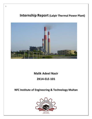
  • 1. 1 Internship Report (Lalpir Thermal Power Plant) Malik Adeel Nasir 2K14-ELE-101 NFC Institute of Engineering & Technology Multan
  • 2. 2 Table of Contents The Group:.................................................................................................................................................................5 Associated Companies – Listed....................................................................................................................................5 POWER STATION:.......................................................................................................................................................6 Lalpir Thermal Power.............................................................................................................................................6 Unit 1: Lalpir...............................................................................................................................................................7 Unit 2: Pakgen............................................................................................................................................................7 Mission Statement......................................................................................................................................................7 Boiler.........................................................................................................................................................................8 Water Tube Boiler......................................................................................................................................................8 Balance of Plant (B.O.P) ..............................................................................................................................................9 Steps involving in Water treatment:.............................................................................................................................9 Steam turbine At LAL PIR...........................................................................................................................................10 Generator at LAL PIR.................................................................................................................................................11 What is a switch yard?..............................................................................................................................................11 SWITCH YARD OPERATION ACTIVITIES:......................................................................................................................12 SWITCH YARD EQUIPMENT .......................................................................................................................................13 Surge Arrestor:.........................................................................................................................................................14 How does a surge arrester operate?..........................................................................................................................14 Metal Oxide Varistor:................................................................................................................................................14 2 . CURRENT TRANSFORMER (CT): .............................................................................................................................14 3. CAPACITIVE VOLTAGE TRANSFORMER (CVT):.......................................................................................................15 4. BUS BAR:............................................................................................................................................................16 Advantage and Disadvantage of Bus Bar: ...................................................................................................................17 Single Bus-BarArrangement.................................................................................................................................17 Single Bus-BarArrangementwithBusSectionalized.......................................................................................................18 MainandTransferBusArrangement..........................................................................................................................19 5. ISOLATOR:-...........................................................................................................................................................20 Purpose:..................................................................................................................................................................20 Types of Isolation: ....................................................................................................................................................21 6. CIRCUIT BREAKER:-................................................................................................................................................22 Types of Circuit Breaker............................................................................................................................................23 Circuir Breaker that are used bylal pir .......................................................................................................................24 Types of SF6 Circuit Breaker..............................................................................................................................24 7. WAVE TRAP:-........................................................................................................................................................25
  • 3. 3 EARTHING SWITCH:-.................................................................................................................................................27 Conductor:...............................................................................................................................................................27 What are the uses of conductors? .............................................................................................................................28 Different types of conductor: ....................................................................................................................................28 Insulator:.................................................................................................................................................................29 What is an electrical insulator?..................................................................................................................................29 Types of Electrical Insulator.......................................................................................................................................29 Pin Insulator.........................................................................................................................................................29 Post Insulator........................................................................................................................................................30
  • 4. 4
  • 5. 5 The Group: Nishat group of companies is a premier business house of Pakistan. The group has presence in all major sectors including Textiles, Cement, Banking, Insurance, Power Generation, Hotel Business, Agriculture, Dairy and Paper Products. Today, Nishat Group is considered to be at par with multinationals operating locally in terms of its quality products and management skills. Following is the list of companies in the group. Associated Companies – Listed Adam jee Insurance Limited www.adamjeeinsurance.com DG Khan Cement Company Limited www.dgcement.com Lalpir Power Limited www.lalpir.com MCB Bank Limited www.mcb.com.pk Nishat Chunian Limited www.nishat.net Nishat Power Limited www.nishatpower.com Pakgen Power Limited www.pakgenpower.com
  • 6. 6 POWER STATION: A Power Station is an industrial facility for the generation of electric power. A power plant is an assembly of systems or subsystems which generates electricity in an economical and environmentally friendly way. At the center of nearly all power stations is a generator, a rotating machine that converts mechanical power into electrical power by creating relative motion between a magnetic field and a conductor. The energy source harnessed to turn the generator varies widely. It depends chiefly on which fuels are easily available, cheap enough and on the types of technology that the power company has access to. Most power stations in the world burn fossil fuels such as coal, oil, and natural gas to generate electricity, and some use nuclear power, but there is an increasing use of cleaner renewable sources such as solar, wind, and hydroelectric. Lalpir Thermal Power Lalpir thermal power station was developed in 1997 with the hope of meeting the growing Electricity needs of the Nation followed by Pak Gen in 1998. Lalpir and Pak Gen sell electricity to the Pakistan Water and Power Development Authority (WAPDA), the state-owned utility.
  • 7. 7 Unit 1: Lalpir The Unitwas setup withthe capacity of 365 MW oil firedunderthe New EnergyPolicy(March1994) of the Government of Pakistan. Nichimen Japan was engaged to take turnkey responsibility for EPC Contractor. Unit has commercially operated since November 6, 1997. Unit 2: Pakgen The Unit was set up with the capacity of 365 MW oil fired under the New Energy Policy (March 1994) of the Government of Pakistan. Nichimen Japan was engaged to take turnkey responsibility for EPC Contractor. The Unit has been commercially operational Since February 1, 1998. It is the first ever Flue Gas Desulphurization (Scrubber) System in Pakistan Lal Pir (Pvt.) Limited owns and operates Lal Pir Thermal Power station, most efficient power plant in Pakistan, Located near "Muzaffargarh". Against this contribution we make every effort to balance our commitment to country's energy needs with minimizing environmental impacts on land, air and water. Our generating units are fitted with flue gas desulphurization (FGD) equipment removing 90% of the sulphur dioxide (SO2) from emissions, and work is underway to reduce still further emissions of oxides of nitrogen (NOX). At the same time, by-products of the FGD processes are recycled through their further use in the construction industry. Mission Statement To become a world-class business and consistently stay ahead of any leading power business in the world in everything we do. We believe in responsible industry leadership, creating profitable growth in harmony with environmental sustainability and good corporate citizenship u
  • 8. 8 Boiler A boiler is a closed vessel in which water or other fluid is heated. The heated or vaporized fluid exits the boiler for use in various processesor heating applications. A boiler is a device used for transferring heat liberated by combustion of a fuel to water or steam. It is a pressure vessel, designed to withstand steam pressure, which can be dangerous if not correctly operated and maintained. Water Tube Boiler In water tube boiler, boiler feed water flows through the tubes and enters the boiler drum. The circulated water is heated by the combustion gases and converted into steam at the vapour space in the drum. These boilers are selected when the steam demand as well as steam pressure requirements are high as in the case of process cum power boiler / power boilers. Boiler at LAL PIR/PAKGEN The boiler at Lalpir/PakGen is Mitsubishi forced circulation radian reheat Boiler capable of performing two operations at outlet for turbine:
  • 9. 9  Provides superheated steam to the High Pressure (HP) turbine.  Provides reheated steam to the intermediate Pressure (IP) turbine Balance of Plant (B.O.P) Major function performed by BOP is water intake andits treatment. Water is an excellent solvent so a chain of steps are followed for its thorough treatment. Water treatment is imperative for optimal performance of a power plant. Steps involving in Water treatment:  Water intake There are two sources of water for the plant. One is underground water and the other is canal water. Mostly canal water is used because it contains less dissolved impurities (but greater suspended impurities) than underground water. Two intake pipes bring raw water from the canal, which then divides into two branches.  Bar screens The raw water is then collected into pit for bar screen, whose primary purpose is to remove large materials which could damage plant equipment and reduce the qualityof the bio solids. The bar screens remove materials greater than about 1/4" in size.  Canal intake pumps The raw water is then pumped to the power plant with the help of canal intake water pump, each pump is supplied with pneumatically controlledvalve which when open recirculated the water back to the bar screen  Clarifier The process ofremoving colloidal materials from water. A chemical coagulant (for example, alum) or a chemical flocculants (for example, polymer) or both are added to the water.  DMF (dual media filter) A media filter is a type of filter utilizing a bed of sand, crushed granite or other material to filter water. A dual media filter is one using 2mediums for the purpose.
  • 10. 10  Filtered water basin Water after passing through dual media filters is discharged into the filter water basin from where makeup water for the cooling tower is taken and the rest is pumped forwarded for further treatment  Multimedia filter Multimedia filters are those which have more than two filtering Medias. The Medias used at AES Lalpir are: 1. Garnet 2. Anthracite 3. Filter sand 4. 5 micron filter  Reverse Osmosis Application of an external pressure to the salt solution side equal to the osmotic pressure will also cause equilibrium.  DE carbonator Between the cation unit and the anion unit lays theDE carbonator which removes carbon dioxide from the water.  Ion exchange process The function of ion exchange process is to remove dissolved solids from the water in plant systems, which helps preventing problems such as corrosion and scale. Steam turbine At LAL PIR Single reheat condensing tandem two cylinder double flow exhaust The steam turbine at AES is operating at simple Rankine cycle with a reheat. There are basically 3 turbines used: high pressure, intimidate pressure, and low pressure Gross capacity of Lal Pir: 362 MW Gross capacity of Pak Gen: 365 MW Max speed of rotation of turbine 3000 rpm. Direction of rotation: Clockwise Inlet pressure at main steam valve: 169 kg/cm2 Inlet temperature at main steam valve: 538 C
  • 11. 11 Reheat temperature at main steam valve: 538 C Exhaust pressure at condenser top: 692 mm Hg No. of extractions for feed water heating: 8 stages Total number of stages = 34 1. HP turbine : 1 impulse 2.HP turbine : 11 reaction Generator at LAL PIR Maximum continuous rating 362 MW Rated terminal voltage 24000 Volts Frequency 50 Hz Rated speed 3000 RPM No of poles 2 Excitation current 3246 Amps Excitation voltage 290 Volts What is a switch yard? It is a switching station which has the following credit:  Main link between Generation plant and Transmission system, which has large influence on the security of the supply.  Step-up and /or Step-down the voltage levels depending upon the Network Node.
  • 12. 12 Figure : Switchyard SWITCH YARD OPERATION ACTIVITIES: A switching station may also be known as a switch yard, and these are commonly located directly adjacent to or nearby a power station. In this case the generators from the power station supply their power into the yard onto the Generator Bus on one side of the yard, and the transmission lines take their power from a Feeder Bus on the other side of the yard. 1. Identifying of faulty equipment, safe isolation of equipment without disturbing other system as much as possible, raising job cards, arranging shutdowns, trial charging and normalization of 400 KV SWYD. And 132KV Switch yard, associated equipment like CBs, Isolator, Shunt Reactors,, Battery, Charges PLCC equipment, Switch yard. Compressors and lighting. 2. Daily inspection of indoor/outdoor switch yard equipment, checking of oil leakages, temperatures and any other abnormalities like sparks etc. SF6 gas pressures, compressed air pressures, running period of compressors.
  • 13. 13 SWITCH YARD EQUIPMENT To perform switchyard operation activities perfectly, operation staff should have good knowledge about the equipment provided in switchyard as well as in control room. They should be familiar with the control system adopted here and a good understanding about the procedures to be followed during the emergencies, outage requirements and charging. Brief description about switchyard equipment is given below. Equipments commonly found in switchyard:- 1. Lightening arrestor 2. Current transformer 3. Voltage transformer 4. Bus bar and clamp fittings 5. Isolators 6. Circuit breaker 7. Wave traps 8. Earthing switch 9. Conductor 10. insulator
  • 14. 14 Surge Arrestor: A surge arrester is a device to protect electrical equipment from over-voltage transients caused by external (lightning) or internal (switching) events. How does a surge arrester operate? The surge arrester does not absorb all of the high voltage that passes through it. It simply diverts it to the ground or clamps it to minimize the voltage that passes through it. The secret to the arrester's successin diverting lightning or high electrical surges is the MOV or the Metal Oxide Varistor Metal Oxide Varistor: The Metal Oxide Varistor or MOV for short, is a voltage dependant resistor in which the resistance material is a metallic oxide, primarily zinc oxide (ZnO) pressed into a ceramic like material. Metal oxide varistors consist of approximately 90% zinc oxide as a ceramic base material plus other filler materials for the formation of junctions between the zinc oxide grains. 2 . CURRENT TRANSFORMER (CT):  Current transformers are used for the instrumentation, Protection or metering of power systems.  Purpose:- - To step-down the high magnitude of current to a safe value to incorporate Measuring and Protection logics. Current transformer (CT) is used for measurement of electric currents. A current transformer (CT) is a type of transformer that is used to measure AC Current. It produces an alternating current (AC) in its secondary which is proportional to the AC current in its primary. Current transformers, together with voltage transformers (VTs) or potential transformers (PTs), which are designed for measurement, are known as an Instrument transformer. The main tasks of instrument transformers are:
  • 15. 15 − To transform currents or voltages from a usually high value to a value easy to handle for relays and instruments − To insulate the metering circuit from the primary high voltage system. − To provide possibilities of standardizing the instruments and relays to a few rated currents and voltages. Construction:- Current transformers typically consist of a silicon steel ring core wound with many turns of copper wire as shown in the illustration to the right. The conductor carrying the primary current is passed through the ring. The CT's primary therefore consists of a single 'turn'. The primary 'winding' may be a permanent part of the current transformer. 3. CAPACITIVE VOLTAGE TRANSFORMER (CVT):  Voltage transformer are required for the operation of many types of instrumentation and relay protective systems. They measure voltage in conjunction with CT, they measure power.  Purpose : - - To step-down the high magnitude of voltage to safe value to incorporate measuring and protection logics. A capacitor voltage transformer (CVT or CCVT), is a transformer used in power systems to step down extra high voltage signals and provide a low voltage signal, for metering or operating a protective relay. CVTs step- down the system voltage to sufficiently low value (110 V) for measuring, protection and synchronizing circuits. CVT has a H.F. terminal point for receiving & transmitting the high frequency signals for carrier protection and communication. CVT Voltage Frequency Response:- With the rated load at the voltage transformer secondary side, The output voltage of CVT initially decrease a little bit, then reaches the resonance peak at around 800 Hz. Then it decreases drastically and remains almost level out after 2000hz. CVT Current Frequency Response:-
  • 16. 16 The C2 current is linear with frequency. The frequency response for voltage transformer current has a resonance peak at around 800 Hz. C2 current is substantially larger than voltage transformer current. Other Applications:- The CVT is also useful in communication systems. CVTs in combination with wave traps are used for filtering high-frequency communication signals from power frequency. This forms a carrier communication network throughout the transmission network. 4. BUS BAR:  Bus bar is a thick strip of copper or aluminum that conducts electricity.  Bus bar are used to carry very large currents, or to distribute current to multiple devices with in switchgear or equipment. In electric power distribution, a bus bar (also bus bar, buss bar or bus bar) is a metallic strip or bar, typically housed inside switchgear, panel boards, and bus way enclosures for local high current power distribution. They are also used to connect high voltage equipment at electrical switchyards, and low voltage equipment in battery banks. They are generally uninsulated, and have sufficient stiffness to be supported in air by insulated pillars. These features allow sufficient cooling of the conductors, and the ability to tap in at various points without creating a new joint. . Fig:Bus bar
  • 17. 17 Advantage and Disadvantage of Bus Bar: Bus bars reduce system costs, improve reliability, increase capacitance, and eliminate wiring errors. They also lower inductance and increase capacitance. Plus, the physical structure of bus bars offers unique features in mechanical design. For example, complete power distribution subsystems can also act as structural members of a total system. Multilayer bus bars offer a structural integrity that wiring methods just can’t match. Bus Bars Reduce System Costs A laminated bus bar will lower manufacturing costs by decreasing assembly time as well as internal material handling costs. Various conductors are terminated at customer specified locations to eliminate the guesswork usually associated with assembly operating procedures. A reduced parts count will reduce ordering, material handling and inventory costs. Bus Bars Improve Reliability Laminated bus bars can help your organization build quality into processes. The reduction of wiring errors results in fewer reworks, lower service costs and lower quality costs. Laminated Bus Bars Increase Capacitance Increased capacitance results in decreasing characteristic impedance. This will ultimately lead to greater effective signal suppression and noise elimination. Keeping the dielectrics thin and using dielectrics with a high relative K factor will increase capacitance. Single Bus-Bar Arrangement This is the simplest arrangement consisting of a single set of a bus bar for the full length of the switchboard and to this set of bus bars are connected to all the generators, transformer and feeders as illustrated in the figure. The advantage of single bus bar arrangements are  It has low initial cost.  It requires less maintenance  It is simple in operation
  • 18. 18 Single Bus-Bar Arrangement with Bus Sectionalized The bus-bar may be sectionalized by a circuit breaker and isolating switches so that a fault on one part does not cause a complete shutdown. In a sectionalized bus bar arrangement only one additional circuit breaker is required which does not cost much in comparison to the total cost of the bus bar system.
  • 19. 19 Main andTransfer Bus Arrangement Such types of arrangements used two bus bars, known as main bus-bar and transfer bus-bar used as an auxiliary bus bar. Each generator and feeder may be connected to either bus-bars with the help of bus coupler which consist of a circuit breaker and an isolating switch. In this arrangement, a bus coupler is usually used so that change over from one bus-bar to the other can be carried out under load condition.
  • 20. 20 5. ISOLATOR:-  Isolator is a Disconnected switch and to be operated at no load.  Isolator switch is used to ensure that an electrical circuit is completely de-energized for service or maintenance.  Interlocked with Breakers and Earth switch's.  Isolator is a mechanical switch which isolates a part of circuit from system as when required. Purpose: In electrical engineering, a disconnector, disconnect switch or isolator switch is used to ensure that an electrical circuit is completely de-energized for service or maintenance. Such switches are often found in electrical distribution and industrial applications, where machinery must have its source of driving power removed for adjustment or repair. High-voltage isolation switches are used in electrical substations to allow isolation of apparatus such as circuit breakers, transformers, and transmission lines, for maintenance A switch disconnector combines the properties of the disconnector and the load switch, so it provides the safety isolation function while being able to make and break nominal currents. Fig:Isolator Unlike a CB an IS has no protection capability and is used to physically disconnect any circuit when repairs etc are being done. In a substation switchyard an IS switch would be used to physically disconnect any incoming HV lines to allow work on the transmission line to be performed.
  • 21. 21 An isolator differs from a switch in that it is intended to be opened when the circuit is not carrying current. An isolator is a device used for isolating a circuit or equipment from a source of power. An isolator is a mechanical switching device that, in the open position, allows for isolation of the input and output of a device . Types of Isolation: The isolators depend upon the type and capacity of lines/location at which the substation is present. An isolator is just a disconnecting switch. So there are less complexities involved when increasing the voltage range (since the isolator unlike circuit breakers do not quench the arcing). Moreover these operate in off-load conditions - when the currents are zero. Depending upon the application, single-break, double-break, bus and line isolators are used. Double Break Isolator Single Break Isolator Pantograph type Isolator. Depending upon the position in power system, the isolators can be categorized as Bus side isolator – the isolator is directly connected with main bus Line side isolator – the isolator is situated at line side of any feeder Transfer bus side isolator – the isolator is directly connected with transfer bus. Isolator Advantage & Disadvantage: However, isolators have limited flexibility and their physical requirements can call for significant planning. The enclosed machinery in an isolator system needs to be highly reliable in order to avoid frequent maintenance and the isolator design should provide easy access through glove ports or half-suits to enable adjustments during production. In addition, isolators used in continuous manual operations usually need to be configured to allow for worker comfort.
  • 22. 22 Fig: Isolator Name Palte 6. CIRCUIT BREAKER:-  Circuit breaker is an automatically-operated electrical switch designed to protect an electrical Circuit from damage caused by overload of electricity or short circuit .  A circuit breaker function is to detect a fault condition and, by interrupting continuity, to immediately discontinue electrical flow. A circuit breaker is an automatically operated electrical switch designed to protect an electrical circuit from damage caused by excess current, typically resulting from an overload or short circuit. Its basic function is to interrupt current flow after a fault is detected. Unlike a fuse, which operates once and then must be replaced, a circuit breaker can be reset (either manually or automatically) to resume normal operation.
  • 23. 23 Fig: Circuit breaker It is an automatic device capable of making and breaking an Electrical Circuit under normal and abnormal conditions such as short circuits. SF6 is the arc quenching media for all the 400 KV and 220 KV breakers installed in the switchyard. Pneumatic operating system is provided in AEG, ABB, AREVA and NGEF make breakers and Hydraulic operating system is provided in BHEL make breakers. 132KV breakers provided in 132 KV lines are of Minimum oil type operating on spring charge mechanism. Working Principle of Circuit Breaker:- The circuit breaker mainly consists of fixed contacts and moving contacts. In normal "ON" condition of circuit breaker, these two contacts are physically connected to each other due to applied mechanical pressure on the moving contacts. There is an arrangement stored potential energy in the operating mechanism of circuit breaker which is released if switching signal is given to the breaker. The potential energy can be stored in the circuit breaker by different ways like by deforming metal spring, by compressed air, or by hydraulic pressure. But whatever the source of potential energy, it must be released during operation. Release of potential energy makes sliding of the moving contact at extremely fast manner. Types of Circuit Breaker According different criteria there are different types of circuit breaker. According to their arc quenching media the circuit breaker can be divided as- According to their arc quenching media the circuit breaker can be divided as- Oil circuit breaker. Air circuit breaker.
  • 24. 24 SF6 circuit breaker. Vacuum circuit breaker. According to their services the circuit breaker can be divided as- Outdoor circuit breaker Indoor breaker. According to the operating mechanism of circuit breaker they can be divided as- Spring operated circuit breaker. Pneumatic circuit breaker. Hydraulic circuit breaker. According to the voltage level of installation types of circuit breaker are referred as- High voltage circuit breaker. Medium voltage circuit breaker. Low voltage circuit breaker. Circuir Breaker that are used by lal pir SF6 circuit breaker: In such breakers, sulphur hexaflouride gas (SF6) is used as the arc quenching medium. The sulphur hexaflouride gas (SF6) is an electronegative gas and has a strong tendency to absorb free electrons. The contacts of the breaker are opened in a high pressure flow of sulphur hexaflouride (SF6) gas and an arc is struck between them. The gas capture the conducting free electrons in the arc to form relatively immobile negative ions. This loss of conducting electrons in the arc quickly builds up enough insulation strength to extinguish the arc. Types of SF6 Circuit Breaker There are mainly three types of SF6 CB depending upon the voltage level of application- 1. Single interrupter SF6 CB applied for up to 245 KV(220 KV) system. 2. Two interrupter SF6 CB applied for up to 420 KV(400 KV) system. 3. Four interrupter SF6 CB applied for up to 800 KV(715 KV) system.
  • 25. 25 7. WAVE TRAP:-  Wave traps are used for communication purpose during fault conditions.  It traps high frequency communication signals sent on the line from the remote substation and diverting to the telecom/telephone protection panel in the substation control room. Wave Traps are used at sub-stations using Power Line Carrier Communication (PLCC). PLCC is used to transmit communication and control information at a high frequency over the power lines. This reduces need for a separate infra for communication between sub-stations. How it works:- Signals from main centers far away from the substations are sent which are captured by the routers placed in substations, these are high frequency signals much higher above the power frequency(in kHz), these signals are then trapped by a coupling circuit and are routed to the fields via underground cables. They work at higher frequencies and allows power frequency signals to pass through and traps the communication signals and hence are named wave traps. The communication signals captured and decoded contain signals like trip the CB, or change the tap changer or something of the kind.
  • 26. 26 Fig: Wave trap Wave Traps are used at sub-stations using Power Line Carrier Communication (PLCC). PLCC is used to transmit communication and control information at a high frequency over the power lines. ... Wave trap is used for communication purpose insubstations. Working of wave traps:- It is connected series with transmission line. its used for communication purpose. It will block the high frequency signal (communication signal) and allow the low frequency (power). Wave trap in electrical systems are used for power plant communication through transmission wires. It is a combination of low inductance in series and high capacitance in parallel with transmission wires in power frequencies. But communication signals are very low amplitude and very high frequency signals. So, these signals are nearly open circuited by the inductance and short circuited by the capacitance.That is how wave trap power and communication waves and used in PPC.
  • 27. 27 EARTHING SWITCH:-  Earth switch is used to discharge the voltage on the circuit to the earth for safety.  Earth switch is mounted on the frame of the isolators.  Earth switch is located for each incomer transmission line and each side of the bus –bar section. Earth switch is mounted on the isolator base on the line side or breaker side depending upon the position of the isolator. The earth switch usually comprises of a vertical break switch arm with the contact, which engages with the isolator contact on the line side. Earth switch is required to discharge the trapped charges on the line or equipment (under shut own) to earth for maintaining safety. Earth switch can be operated only from local either by electrical operation or manually. Conductor: , a conductor is an object or type of material that allows the flow of an electrical current in one or more directions. Materials made of metal are common electrical conductors What is a conductor of electricity? An electrical conductor is a substance in which electrical charge carriers,usually electrons, move easily from atom to atom with the application of voltage. Conductivity, in general, is the capacity to transmit something, such as electricity or heat. ... Copper, steel, gold, aluminum, and brass are also good conductors.
  • 28. 28 What are the uses of conductors? Copper is still the most popular material used for wires because it is a very good conductor of electrical current and it is fairly inexpensive when compared to gold and silver. Aluminum and most other metals do not conduct electricity quite as good as copper Different types of conductor: There is no unique process by which all transmission and/or distribution lines are designed. It is clear, however, that all major cost components of line design depend upon the conductor electrical and mechanical parameters. There are three major types of overhead conductors used for electrical transmission and distribution.  AAC - All Aluminum Conductor  ACSR - Aluminum Conductor Steel Reinforced  ACAR - Aluminum Conductor Aluminum-Alloy Reinforced AAC - All Aluminum Conductor, sometimes referred to as ASC, Aluminum Stranded Conductor, is made up of one or more strands of 1350 Alloy Aluminum in the hard drawn H19 temper. 1350 Aluminum Alloy, previously known as EC grade or electrical conductor grade aluminum, has a minimum conductivity of 61.2% IACS. Because of its relatively poor strength-to-weight ratio, AAC has had limited use in transmission lines and rural distribution because of the long spans utilized. ACSR - Aluminum Conductor Steel Reinforced, a standard of the electrical utility industry since the early 1900's, consists of a solid or stranded steel core surrounded by one or more layers of strands of 1350 aluminum. Historically, the amount of steel used to obtain higher strength soon increased to a substantial portion of the cross-section of the ACSR, but more recently, as conductors have become larger, the trend has been to less steel content. To meet varying requirements, ACAR - (Aluminum Conductor-Aluminum Alloy Reinforced) - ACAR combines 1350 and 6201 aluminum alloy strands to provide a transmission conductor with an excellent balance of electrical and mechanical properties. This conductor consists of one or more layers of 1350-H19 aluminum strands helically wrapped over one or more 6201-T81 aluminum alloy wires
  • 29. 29 Insulator: A material or an object that does not easily allow heat, electricity, light, or sound to pass through it. Air, cloth and rubber are good electrical insulators; feathers and wool make good thermal insulators. What is an electrical insulator? An electrical insulator is a material whose internal electric charges do not flow freely; very little electric current will flow through it under the influence of an electricfield. Types of Electrical Insulator There are mainly three types of insulator used as overhead insulator likewise 1. Pin Insulator 2. Suspension Insulator 3. Strain Insulator In addition to that there are other two types of electrical insulator available mainly for low voltage application, e.i. Stay Insulator and Shackle Insulator. Pin Insulator Pin Insulator is earliest developed overhead insulator, but still popularly used in power network up to 33 KV system. Pin type insulator can be one part, two parts or three parts type, depending upon application voltage. In 11 KV system we generally use one part type insulator where whole pin insulator is one piece of properly shaped porcelain or glass.
  • 30. 30 Post Insulator Post insulator is more or less similar to Pin insulator but former is suitable for higher voltage application. Post insulator has higher numbers of petticoats and has greater height. This type of insulator can be mounted on supporting structure horizontally as well as vertically. The insulator is made of one piece of porcelain but has fixing clamp arrangement are in both top and bottom end. The main
  • 31. 31 Suspension Insulator: In higher voltage, beyond 33KV, it becomes uneconomical to use pin insulator because size, weight of the insulator become more. Handling and replacing bigger size single unit insulator are quite difficult task. For overcoming these difficulties, suspension insulator was developed. In suspension insulator numbers of insulators are connected in series to form a string and the line conductor is carried by the bottom most insulator. Each insulator of a sūuspension string is called disc insulator because of their disc like shape.