hvac refragration Pipes size and table
•
3 likes•187 views

quick reference to size the hvac split unit with a short cut of minimum requirments
Recommended

Recommended
More Related Content
What's hot
What's hot (20)
Similar to hvac refragration Pipes size and table
Similar to hvac refragration Pipes size and table (20)
More from MUSTAFA AHMED ABDULJABBAR
More from MUSTAFA AHMED ABDULJABBAR (20)
Recently uploaded
Recently uploaded (20)
hvac refragration Pipes size and table
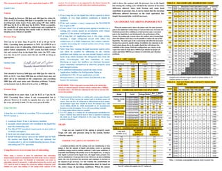
- 1. Max measured length is 200', max equivalent length is 250' Liquid Lines Velocity This should be between 100 fpm and 400 fpm for either R- 410A or R-22.Exceeding 400 fpm is acceptable, but may lead to refrigerant noise issues. 5 ton units using 3/8" lines will be 405 fpm for R-22 or 483 fpm for R-410A. While acceptable, the possibility of noise must be understood and explained to the owner Avoid placing lines inside walls or directly above sleeping areas whenever possible Pressure Drop This can be no more than 35 psi for R-22 or 60 psi for R- 410A. Exceeding those parameters is NOT ALLOWED as it would cause a loss of subcooling which leads to capacity loss and/or failed components. If a HP system has both vertical rise and vertical drop in the liquid line, enter the NET value as a rise. In an A/C system enter the net rise OR net drop as appropriate. Suction Lines Velocity This should be between 1000 fpm and 3000 fpm for either R- 410A or R-22. Less than 1000 fpm on vertical risers may not allow oil to be returned to the compressor and exceeding 3000 fpm will cause noise and vibration problems. Velocity on horizontal runs is allowed to be as low as 800 fpm. Pressure Drop This should be no more than 3 psi for R-22 or 5 psi for R- 410A Exceeding these values is not recommended but is allowed. However it results in capacity loss at a rate of 1% for every psi on R-22 and .7% for every psi on R-410A Long Line Sets A long line set is defined as exceeding 75 Feet in length and MUST include a: 1. crankcase heater if one is not factory installed. 2. normally closed solenoid valve installed in the liquid line near the condensing unit. 3. Non Bleed TXV (standard requirement on most units at 13 SEER and higher). 4. hard start kit (single phase units only). 5. Install Schrader access valves at the indoor unit for both the suction and liquid lines. These are optional, but recommended to aid in troubleshooting pressure drops, subcooling and TXV operation Using Receivers to overcome loss of subcooling When using a receiver it must be understood that subcooling measurements cannot be attempted in the field as the receiver contents are in a saturated state. No hydrolic or hydorstatic seal exists so subcooling cannot be measured. A sight glass between the receiver and TXV must be used to charge the system by adding refrigerant until bubbles are gone, then adding 1/2 the pump down capacity of the receiver. Use of receivers is not supported by the factory because the application typically does not fall within their published guidelines. NOTES: 1. If on a long line set the liquid line will be exposed to direct sunlight, or very high ambient conditions, it should be insulated 2. If the unit contains a rotary compressor the MAXIMUM line length is 100' 3. If more than 5 feet of underground piping is installed on a cooling only system, install an accumulator with volume equal to 1/2 the system's refrigerant volume. 4. If a long line set application uses a two stage system, meaning a single refrigerant circuit with either two compressors or a single compressor that reduces capacity, consider decreasing the vertical suction riser (if one exists) by one line size. 5. Noise from lines running through basements and/or attics can often be avoided by adhearing to the velocity guidelines and taking care use non metalic hangers such as mesh strap which insulates the refrigerant lines from the joists. Overcharging will also contribute to noise. Discharge or vapor line mufflers can eliminate harmonic noises sometimes encountered in otherwise properly sized and charged systems. 6. For addtional information consult the most recent Application Guidlines for Refrigeration Piping as published by UPG. If your application exceeds theseparameters, you must contact Jack Bartell or the factory for assistance REMEMBER: With 2 stage units you must look at the suction line velocity at reduced capacity to insure velocity remains above 1000fpm on suction risers. If it does not, reducing the riser size by one size will correct the problem 1. Slope horizontal suction lines on cooling only systems approximately 1 inch every 20 feet toward the outdoor unit to facilitate proper oil return. Since the flow of refrigerant is bidirectional on heat pumps, all horizontal vapor lines should be level. Pre-charged lines with excess tubing should be coiled horizontally in an inconspicuous location to avoid oil trapping. Never coil excess tubing vertically. 2. Use long radius elbows wherever possible 3. Use PVC piping as a conduit for all underground installations.See Figure 2. Buried lines must be kept as short as possible to minimize the build up of liquid refrigerant in the vapor line during long periods of shutdown. TRAPS Traps are not required if the piping is properly sized. Traps will only add pressure drop to the system, further reducing capacity INDOOR UNIT ABOVE OUTDOOR UNIT a common problem with the cooling cycle (air conditioning or heat pump) is that the amount of liquid sub-cooling varies as operating conditions change (such as outdoor ambient). Under some conditions, it is possible that flashing will actually occur in the liquid riser. As long as only liquid is present in the liquid riser, the liquid static pressure loss can be calculated at 1/2 psi per foot of rise. However, as soon as flashing starts, the rate of pressure loss increases and continues to increase as the amount of gas increases. For this reason, the restrictions on elevation differences for this configuration must be based on the entire range of operating conditions. When the indoor unit is above the outdoor unit, the pressure loss in the liquid line during the cooling cycle will limit the amount of elevation difference allowed. Since both friction and static head contribute to pressure loss, it can be stated that the elevation difference allowed decreases as the total equivalent line length (horizontal plus vertical) increases. OUTDOOR UNIT ABOVE INDOOR UNIT When the outdoor unit is above the indoor unit, the static pressure gain in the liquid line vertical drop (1/2 psi per foot) may overcome the frictional pressure loss resulting in a total pressure gain. A pressure gain in the liquid line is not detrimental to the performance of the system. On cooling only systems where the outdoor unit is located high above the indoor coil, it may even be possible to reduce the size of the liquid line. The static gain in the vertical drop will offset the increased friction loss caused by smaller tubing. In addition, the reduction in the total system charge due to the smaller liquid line will enhance the reliability of the system. With this configuration, gas velocity in the vapor riser must be kept above 1000 feet per minute for proper oil return and below 3000 feet per minute to avoid noise and vibration problems.