Crystal structure of metals and semiconductors
•Download as PPTX, PDF•
2 likes•500 views

Material Science 01

Recommended
More Related Content
What's hot
What's hot (20)
Similar to Crystal structure of metals and semiconductors
Similar to Crystal structure of metals and semiconductors (20)
Recently uploaded
Recently uploaded (20)
Crystal structure of metals and semiconductors
- 1. The Structure of Crystalline Solids 1
- 2. WHY STUDY The Structure of Crystalline Solids? The properties of some materials are directly related to their crystal structures. For example, pure and undeformed magnesium and beryllium, having one crystal structure, are much more brittle (i.e., fracture at lower degrees of deformation) than are pure and undeformed metals such as gold and silver that have yet another crystal structure. Furthermore, significant property differences exist between crystalline and noncrystalline materials having the same composition. For example, noncrystalline ceramics and polymers normally are optically transparent; the same materials in crystalline (or semicrystalline) form tend to be opaque or, at best, translucent. 2
- 3. Learning Objectives 1. Describe the difference in atomic/ molecular structure between crystalline and non-crystalline materials. 2. Draw unit cells for face-centered cubic, body-centered cubic, and hexagonal close- packed crystal structures. 3. Derive the relationships between unit cell edge length and atomic radius for face-centered cubic and body-centered cubic crystal structures. 4. Compute the densities for metals having face-centered cubic and body-centered cubic crystal structures given their unit cell dimensions. 5. Given three direction index integers, sketch the direction corresponding to these indices within a unit cell. 6. Specify the Miller indices for a plane that has been drawn within a unit cell. 7. Describe how face-centered cubic and hexagonal close-packed crystal structures may be generated by the stacking of close- packed planes of atoms. 8. Distinguish between single crystals and polycrystalline materials. 9. Sketch/describe unit cells for sodium chloride, cesium chloride, zinc blende, diamond cubic, fluorite, and perovskite crystal structures. 10. Given the chemical formula for a ceramic compound and the ionic radii of its component ions, predict the crystal structure. 3 After studying this chapter, you should be able to do the following:
- 4. Structure of Crystalline Materials • Crystal Structure of Metallic and Semiconductor Elements: – Cubic, Face-centered cubic (FCC), Body-centered cubic (BCC) and – Diamond cubic structures; • Crystals Structures of Ceramics: – Rock Salt, – Cesium Chloride, Zinc Blende (Sphalerite), – Fluorite and Perovskite Structures; – Fullerenes and Carbon Nano-tube Structure 4
- 5. Crystal Structures • The arrangement of atoms, ions or molecules in a material constitute the Crystal Structure • If the arranged pattern repeats itself in 3- dimension, the result is a crystal structure. • The properties of some materials are directly related to their crystal structures. • Significant property differences exist between crystalline and non-crystalline materials having the same composition. 5
- 6. Unit Cell and Space lattice of ideal Crystalline solid 6 Space Lattice: A 3-D regular arrangements of atoms characteristic of a particular crystal structure (points of intersection of a network of lines in 3-D). 14 such arrangements exist called Bravais Lattice Unit Cell: The smallest building block of a crystal, consisting of atoms, ions, or molecules, whose geometric arrangement defines a crystal's characteristic symmetry and whose repetition in space produces a crystal lattice.
- 7. Lattice Constants (Lattice Parameters) • Three lattice vectors a, b, c and the inter-axial angles α, β, γ are called the lattice constants or lattice parameters of a unit cell. 7 A unit cell showing lattice constants
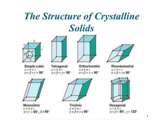
- 8. 8 • This results in the fact that, in 3 dimensions, there are only • 7 different shapes of unit cell which can be stacked together to completely fill all space without overlapping. • This gives the 7 crystal systems, in which all crystal structures can be classified. These are: • The Cubic Crystal System (SC, BCC, FCC) • The Hexagonal Crystal System (S) • The Triclinic Crystal System (S) • The Monoclinic Crystal System (S, Base-C) • The Orthorhombic Crystal System (S, Base-C, BC, FC) • The Tetragonal Crystal System (S, BC) • The Trigonal (or Rhombohedral) Crystal System (S) Classification of Crystal Structures Crystallographers showed a long time ago that in 3-D, there are 7 CRYSTAL SYSTEMS with 14 BRAVAIS LATTICES
- 12. Relation of the primitive cell in the hexagonal system (heavy lines) to a prism of hexagonal symmetry. Here a1 = a2 ≠ a3. Hexagonal System In this Fig. the lattice vectors are: a = a ≠ c α = β = 90̊ and γ = 120̊
- 14. 14 • Non dense, random packing • Dense, ordered packing Dense, ordered packed structures tend to have lower energies. Energy and Packing Energy r typical neighbor bond length typical neighbor bond energy Energy r typical neighbor bond length typical neighbor bond energy
- 15. 15 • atoms pack in periodic, 3D arrays Crystalline materials... -metals -many ceramics -some polymers • atoms have no periodic packing Noncrystalline materials... -complex structures -rapid cooling crystalline SiO2 noncrystalline SiO2"Amorphous" = Noncrystalline Materials and Packing Si Oxygen • typical of: • occurs for:
- 16. 16 Metallic Crystal Structures • How can we stack metal atoms to minimize empty space? 2-dimensions vs.
- 17. 17 • Tend to be densely packed. • Reasons for dense packing: -Typically, only one element is present, so all atomic radii are the same. -- Metallic bonding is not directional. -- Nearest neighbor distances tend to be small in order to lower bond energy. - The “electron cloud” shields cores from each other • They have the simplest crystal structures. Metallic Crystal Structures
- 18. 18
- 19. 19 • Rare due to low packing density only Polonium (Po, At. No. 84) has this structure) • Close-packed directions are cube edges. Atoms per unit cell: 01, • Coordination # = 6 (# nearest neighbors) Simple Cubic Structure (SC)
- 20. 20 • APF for a simple cubic structure = 0.52 APF = a3 4 3 p (0.5a) 31 atoms unit cell atom volume unit cell volume Atomic Packing Factor (APF) APF = Volume of atoms in unit cell* Volume of unit cell *assume hard spheres close-packed directions a R=0.5a contains 8 x 1/8 = 1 atom/unit cell
- 21. 21 • Coordination # = 8 • Atoms touch each other along cube diagonals. All atoms are identical. Body Centered Cubic Structure (BCC) ex: Cr, W, Fe (), Tantalum, Molybdenum 2 atoms/unit cell: 1 center + 8 corners x 1/8
- 22. 22
- 23. 23 Atomic Packing Factor: BCC a APF = 4 3 p ( 3a/4)32 atoms unit cell atom volume a3 unit cell volume length = 4R = Close-packed directions: 3 a • APF for a body-centered cubic structure = 0.68 a R a2 a3
- 24. 24 • Coordination # = 12 • Atoms touch each other along face diagonals. --Note: All atoms are identical; the face-centered atoms are shaded differently only for ease of viewing. Face Centered Cubic Structure (FCC) ex: Al, Cu, Au, Pb, Ni, Pt, Ag 4 atoms/unit cell: 6 face x 1/2 + 8 corners x 1/8
- 25. 25
- 27. 27 • APF for a face-centered cubic structure = 0.74 Atomic Packing Factor: FCC maximum achievable APF APF = 4 3 p ( 2a/4)34 atoms unit cell atom volume a3 unit cell volume Close-packed directions: length = 4R = 2 a Unit cell contains: 6 x1/2 + 8 x1/8 = 4 atoms/unit cell a 2 a
- 28. 28 Hexagonal Close-Packed Structure (HCP)
- 29. 29
- 30. 30
- 31. 31 • Coordination # = 12 • ABAB... Stacking Sequence • APF = 0.74 • 3D Projection • 2D Projection Hexagonal Close-Packed Structure (HCP) 6 atoms/unit cell ex: Cd, Mg, Ti, Zn • c/a = 1.633. Do it by yourself?? c a A sites B sites A sites Bottom layer Middle layer Top layer
- 33. Closed packed structures 33 A portion of a closed-packed plane of atoms; A, B, and C position are indicated. The AB stacking sequence for close- packed atomic planes . ABAB stacking sequence for hcp. ABCABC stacking sequence for fcc. A corner has been removed to show the relation between the stacking of close- packed planes of atoms and the fcc crystal structure, the heavy triangle outlines a (111) plane. .
- 34. Figure. Workflow for solving the structure of a molecule by X-ray crystallography. Crystal Diffraction pattern Electron Density Map Atomic Model
- 35. What are X-rays? X-rays: Electromagnetic radiation with a wavelength from 0.1 Ǻ to 100 Ǻ (0.01 nm to about 10 nm).
- 36. What are X-rays • Discovered in 1895 AD by Wilhelm Roentgen and got first Noble prize in Physics in 1901 AD. • X-rays are a part of the electromagnetic spectrum along with visible light, Infra Red, Ultra Violet etc. • The λ could be 10-8 to 10-11 meter (0.01 to 10 nm, which is almost comparable to lattice parameter or interatomic distance). • The frequencies are in the range of 3 x 10¹⁶ Hz to 3 x 10¹⁹ Hz and energies in the range of 100 eV to 100 keV. • The shorter λ’s are called hard x-rays while longer λ’s are known as soft X-rays (the shorter the λ, more energy the radiation has).
- 37. Generation of X-radiation for diffraction measurements • Sealed X-ray tubes tend to operate at 1.8 to 3 kW. • Rotating anode X-ray tubes produce much more flux because they operate at 9 to 18 kW. – A rotating anode spins the anode at 6000 rpm, helping to distribute heat over a larger area and therefore allowing the tube to be run at higher power without melting the target. • The Cu (or Co, Mo, Cr) source generates X rays by striking the anode target with an electron beam from a tungsten filament. – The target must be water cooled. – The target and filament must be contained in a vacuum. Cu H2O In H2O Out e- Be XRAYS window Be XRAYS FILAMENT ANODE (cathode) AC CURRENT window metal glass (vacuum) (vacuum)
- 38. The Principle of Bremsstrahlung Generation X-ray, (continuous or Bremsstrahlung) Fast incident electron nucleus Atom of the anode material electrons Ejected electron (slowed down and changed direction)
- 40. An x-ray emission spectra for Cu 40
- 41. X-Ray Diffraction and Determination of Crystal Structure 41 Using X-ray diffractometry. • Crystal structure, • Inter-planar distance, • Phase composition and • many more parameters can be determined.
- 42. Xray-Tube Detector Sample Bragg´s Equation λ = 2dsinθ d – distance between the same atomic planes λ – monochromatic wavelength θ – angle of diffracto-meter Xray-Tube Detector Metal Target (Cu or Co) X-Ray Diffractometer
- 43. Diffraction of x-rays from two planes 43 Diffraction of x-rays by planes of atoms (A – A’ and B-B); Bragg’s Law
- 44. 44
- 45. 45
- 46. • Calculation of d-spacing and lattice parameters using Bragg’s Law, (220) plane in a unit cube
- 48. 48 3367 Atm)
- 49. 49 Theoretical Density, r where n = number of atoms/unit cell A = atomic weight VC = Volume of unit cell = a3 for a cubic structure NA = Avogadro’s number = 6.022 x 10²³ atoms/mol Density = r = VC NA n A r = CellUnitofVolumeTotal CellUnitinAtomsofMass
- 50. 50 • Example: Cr (BCC) A (atomic weight) = 52.00 g/mol n = 2 atoms/unit cell R = 0.125 nm rtheoretical a = 4R/ 3 = 0.2887 nm ractual a R r = a3 52.002 atoms unit cell mol g unit cell volume atoms mol 6.022x10²³ Theoretical Density, r = 7.18 g/cm3 = 7.19 g/cm3
- 51. Ceramic Materials • Name comes from Greek letter “Keramicos” mean burnt off. (so these materials are fabricated at high temperature). • Ceramic materials are inorganic and nonmetallic material, • Metallic and non-metallic elements are bonded together, • Materials could be totally ionic or predominantly ionic with covalent character or totally covalent. 51
- 52. • Properties depend upon nature of bonding and crystal structure. • In general, Ceramic are hard and brittle, • Good electrical and thermal insulators. • Have high melting point and high chemical stability. • Being used in very harsh environments (say at high Temp. 52
- 53. 53
- 54. 54 • Bonding: -- Can be ionic and/or covalent in character. -- % ionic character increases with difference in electronegativity of atoms. • Degree of ionic character may be large or small: Atomic Bonding in Ceramics SiC: small CaF2: large
- 55. Ceramics materials have two major categories • Traditional and Engineering ceramic materials. • Traditional Ceramics are fabricted from “clay”, silica (flint) and feldspar (rock forming silicate of Al together with Na, K. Ca, and Ba). • Examples are: – Porcelain, bricks, tiles, and in addition, glasses and high temperature ceramics. 55 • Engineering Ceramics; • These are pure or nearly pure compounds of Aluminum Oxide Al2O3, Silicon Carbide (SiC), and Silicon Nitrate (Si3Ni4). • They are being used in: • I.T. Technology (Al2O3) • In high temperature areas (SiC), furnaces and many more.
- 56. Crystal structure of Ceramics • The metallic ion could be; – Cation: Positively ion, (e- has left the atom) – Anion: Negatively ion (e- is gained in the atom. • In ionic compounds, packing of ions determine by: – The relative size of the ions in the ionic solid. – The need to balance electrostatics charges to maintain electrical neutrality in the ionic solid. 56
- 57. 57 Table 12.3: Ionic Radii for Several Cations and Anions for a Coordination Number of 6 • The size of an ion depends on several factors. • One of these is coordination number: ionic radius tends to increase as the number of nearest-neighbor ions of opposite charge increases. • Ionic radii given in Table 12.3 are for a coordination number of 6. • Therefore, the radius is greater for a coordination number of 8 and less when the coordination number is 4. In addition, the charge on an ion will influence its radius. For example, from Table 12.3, the radii for Fe2+and Fe3+ are 0.077 and 0.069 nm, respectively, which values may be contrasted to the radius of an iron atom—0.124 nm. When an electron is removed from an atom or ion, the remaining valence electrons become more tightly bound to the nucleus, which results in a decrease in ionic radius. Conversely, ionic size increases when electrons are added to an atom or ion.
- 58. 58 Factors that Determine Crystal Structure 1. Relative sizes of ions – Formation of stable structures: --maximize the # of oppositely charged ion neighbors. - - - - + unstable - - - - + stable - - - - + stable 2. Maintenance of Charge Neutrality : --Net charge in ceramic should be zero. --Reflected in chemical formula: CaF2: Ca2+ cation F- F- anions+ AmXp m, p values to achieve charge neutrality
- 59. • For a Bravais Lattice, The Coordinatıon Number The number of lattice points closest to a given point (the number of nearest-neighbors of each point). • Because of lattice periodicity, all points have the same number of nearest neighbors or coordination number. (That is, the coordination number is intrinsic to the lattice.) Examples Simple Cubic (SC) coordination number = 6 Body-Centered Cubic coordination number = 8 Face-Centered Cubic and HCP, coordination number = 12 Coordination Number
- 60. 60 • Coordination # increases with Coordination # and Ionic Radii 2 rcation ranion Coord # < 0.155 0.155 - 0.225 0.225 - 0.414 0.414 - 0.732 0.732 - 1.0 3 4 6 8 linear triangular tetrahedral octahedral cubic rcation ranion To form a stable structure, how many anions can surround a cation? (Zinc blende)
- 61. 2 <0.155 3 0.155 – 0.255 4 0.225 – 0.414 0.414 – 0.7326 0.732 – 1.08
- 62. 62 Computation of Minimum Cation-Anion Radius Ratio • Determine minimum rcation/ranion for an octahedral site (C.N. = 6) a = 2ranion 2ranion 2rcation = 2 2ranion ranion rcation = 2ranion rcation = ( 2 1)ranion arr 222 cationanion = 414.012 anion cation == r r a Measure the radii (blue and yellow spheres) Substitute for “a” in the above equation
- 63. 63 • On the basis of ionic radii, what crystal structure would you predict for FeO? • Answer: 5500 1400 0770 anion cation . . . r r = = Example Problem: Predicting the Crystal Structure of FeO Ionic radius (nm) 0.053 0.077 0.069 0.100 0.140 0.181 0.133 Cation Anion Al3+ Fe2+ Fe3+ Ca2+ O2- Cl- F- based on this ratio, -- coord # = 6 because 0.414 < 0.550 < 0.732 -- crystal structure is similar to NaCl
- 64. AX type Crystal Structure 64 • The ceramic materials with AX type Crystal Structure have; • Number of Cation = Number of Anions • Where ‘A’ denotes cations and ‘X’ the anion • Several different AX compounds exist, • Each is normally named after a common material that assumes the particular structure Examples: • Rock Salt, NaCl • Cesium Chloride, CsCl • Zinc Blende (ZnS)
- 65. 65 Rock Salt Structure Same concepts can be applied to ionic solids in general. Example: NaCl (rock salt) structure rNa = 0.102 nm rNa/rCl = 0.564 cations (Na+) prefer octahedral sites rCl = 0.181 nm
- 66. 66 MgO and FeO O2- rO = 0.140 nm Mg2+ rMg = 0.072 nm rMg/rO = 0.514 cations prefer octahedral sites So each Mg2+ (or Fe2+) has 6 neighbor oxygen atoms MgO and FeO also have the NaCl structure
- 67. 67 CsCl Crystal Structures 939.0 181.0 170.0 Cl Cs == r r Cesium Chloride structure: Since 0.732 < 0.939 < 1.0, cubic sites preferred So each Cs+ has 8 neighbor Cl- CsCl is an AX-type Crystal Structures
- 68. Zinc blende (ZnS) Crystal Structure 68 A unit cell for the zinc blende (ZnS) crystal structure • Zinc blende or Sphalerite structure • Coordination No. = 4, • All corner's and face positions occupied by S atoms, • Zn atoms fill interior tetrahedral position. • Reverse structure is also possible (Zn, S position reversed) • Each Zn atom is bonded to 4 S atoms, • Atomic bonding is highly covalent; • Include: • ZnS, • ZnTe, • SiC
- 69. 69 AX2 Crystal Structures • Calcium Fluorite (CaF2) • Calcium ions in cubic sites • Fluorine ions at the corners • Similar to CsCl, except that only half the center cube positions occupied by Ca2+ ions • Charges on cation ≠ anions • UO2, ThO2, ZrO2, CeO2, PuO2 • Coordination No. = 8 • Antifluorite structure also exists • in which positions of cations and anions are reversed. Fluorite structure
- 70. 70 ABX3 Crystal Structures • Perovskite structure Ex: Complex oxide BaTiO3
- 71. ABX3 Crystal Structures • More than one type of cation. • For two types of Cations (represented by A and B), chemical formula is listed above. • Examples are; – CaTiO3, BaTiO3, SrZrO3, SrSnO3 etc. • Perovskite Crystal Structure is shown on R.H.S. • Ca2+ and O2- ions at the center of the faces of the unit cell. • The highly charged Ti4+ ion is located at the octahedral interstitial site at the center of the unit cell and is coordinated to six O2- ions. • BaTiO3 has the perovskite structure above 1200 C, but below, it is slightly changed. 71
- 72. Structure of some ceramics 72
- 73. 73 • Atoms may assemble into crystalline or amorphous structures. • We can predict the density of a material, provided we know the atomic weight, atomic radius, and crystal geometry (e.g., FCC, BCC, HCP). SUMMARY • Common metallic crystal structures are FCC, BCC and HCP. Coordination number and atomic packing factor are the same for both FCC and HCP crystal structures. • Ceramic crystal structures are based on: -- maintaining charge neutrality -- cation-anion radii ratios. • Interatomic bonding in ceramics is ionic and/or covalent.
- 74. Silicate Ceramics 74 The arrangement of silicon and oxygen atoms in a unit cell of cristobalite, a polymorph of SiO2.
- 75. Silica (SiO2) 75 • Most simple silicate material • 3-D network generated when every corner O2 atom of one tetrahedron is shared by adjacent tetrahedron. • Electrically, material is neutral, so stable electronic structure is formed. • Three primary polymorphic structures of silica, • a). Quartz, b). Cristobalite, and c). Tridymite. • Complicated and relatively open structure • Low densities, • Due to strong Si-O interatomic bonds, melting • point is relatively high 17100 C. The arrangement of silicon and oxygen atoms in a unit cell of cristobalite, a polymorph of SiO2.
- 76. Silica Glass • A form of silica which is non-crystalline solid or glass. • Having high degree of atomic randomness. 76 Search out what type of materials are: Network Formers Network modifiers, Intermediates
- 77. Simple Silicate 77 Fig. 12.12. Five silicate ion structures formed SiO4- 4 tetrahedron
- 78. 78 A unit cell for the diamond cubic crystal structure Carbon Structures • Diamond, Graphite, Fullerene, Carbon Nanotube (CNT) • In diamond, each C atom is bonded to 4 other C atoms. • 4 tetrahedral sites with covalent bonding • Ge, Si and Gray tin (below 13̊ C) have this structure.
- 79. 79 C60 or fullerene Molecule 20 hexagons, 12 pentagons The structure of Graphite C atom Different Structures of C
- 80. 80