2. 724 Prafull A. Desale et al
series APF compensates voltage based distortions. Hybrid APF is applied for filtering
high order harmonics. However, they have a problem that their rating is sometimes
very close to load (up to load 80 %) in typical applications. Due to this reason, power
quality level is not obtained. This causes power disturbances and customer
dissatisfaction. To increase the reliability of the distribution system and face the
power disturbance problems, an advanced power electronics controller devices have
launched over last decades. The evolution of power electronics controller devices has
given to the birth of custom power.
Custom power devices
Custom power is a strategy, which is intended principally to convene the requirement
of industrial and commercial consumers. The concept of the custom power is tools of
application of power electronics controller devices into power distribution system to
supply aquality of power, demanded by the sensitive users.
These power electronics controller devices are also called custom power devices
because through these valuable powers is applied to the customers. They have good
performance at medium distribution levels and most are available as commercial
products. For the generation of custom power devices VSI is generally used, due to
self-supporting of dc bus voltage with a large dc capacitor. The custom power devices
are mainly divided into two groups: network reconfiguring type and compensating
type. The complete classification of custom power devices is shown in the figure.
Fig 1.Custom power devices
Power quality issue
Various power quality problems:-Power surge, voltage spikes, notching, blackout,
brownout, voltage flickering, harmonic, and voltage unbalance.
Network reconfiguring type custom power devices
These are GTO or Thyristor based devices, generally used for fast current limiting and
current breaking. The main network reconfiguring type custom power devices are:
solid state current limiter, static transfer switch, static breaker, ups.
3. Brief Review Paper on the Custom Power Devices for Power Quality Improvement 725
A. Static Current Limiter.
It is a series connecting devices that reduces fault current level by inserting series
inductance in faulty path.it consists of pair of GTO with snubber circuit and inductor.
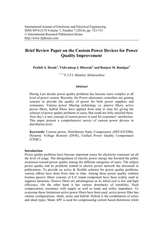
B. Static Transfer Switch.
Static Transfer Switch (STS) is used to protect sensitive load voltage sag or swell. It is
composed of two parallel connected Thyristor or GTO blocks. Each block consists of
three GTO or thyristor corresponding to the three phase of the system. The common
configuration of STS in distribution system is shown in Fig 2.
Fig.2 static transfer switch (STS)
As shown in the Fig 2STS are connected in the bus tie position and contain two
pairs of anti-parallel thyristors to allow fast transfer of power from faulty feeder to an
alternative feeder within the time scale of milliseconds When fault occurs primary
source affected, and then load is fed from alternating source through switch 2. The
STS are effective devices to protect sensitive loads against power quality disturbance,
to ensure rapid transfer between afaulty feeder and healthy feeder, a make-before
break or break-before-make switching strategy is implemented in STS controller
circuit to reduce negative switching impacts on load. Which means it supplied an
uninterrupted power at distribution level to customers. The limitation of this switch is
that, in high power application the load current leads the conducting losses. The
conducting losses are in the range of 0.5 to 1% of the load power. A hybrid STS has
been proposed in this switch a conservative circuit breaker is connected in shunt with
thyristors or GTO’s.
C. Solid State Breaker.
The solid state breaker is based on the GTO or thyristor switching technology. It is a
high- speed switching device, applied to reduces the electrical fault and protect from
4. 726 Prafull A. Desale et al
large current in distribution system. It can be used in a single switch, static transfer
switch, hybrid switch or a low level fault interrupter. The voltage and current rating of
the breaker describes the requirement of no. of switching devices, cost and the losses
of the breaker. It perform auto- reclosing function.
D. Uninterruptible Power Supply.
Uninterruptible power supply (UPS) is the conventional response to circumvent
production interruption and outage costs. The single line diagram of ups is shown in
the Fig 3.
Fig.3 single line diagram of UPS
In UPS load has received the power from source via two stage operation:
conversion (ac/dc) and inversion (dc/ac). During voltage dip or an interruption, the
load voltage is made constant by energy, generated through battery. The performance
of ups is depending on energy storage capacity of battery. For high power load
financially, it is not suitable because of two conversions the maintenance cost of
battery has become too high.
Compensating power devices
The compensating custom power devices are used for active filtering, load balancing,
and power factor improvement voltage regulating (sag / swell). These devices are
mainly three types: static shunt compensator, series and hybrid compensator. These
are also called as DSTATCOM, DVR and UPQC respectively.
A. Distribution Static Compensator (DSTATCOM).
DSTATCOM is a Voltage source inverter (VSI) based static compensator device
(STATCOM, FACTS controller ) applied to maintain bus voltage sags at the required
level by supplying or receiving of reactive power in the distribution system. It is
connected in shunt with distribution feeder with the help of coupling transformer. The
single line diag. of DSTATCOM is shown in shown fig.4. The DSTATCOM consists
of a VSI, dc energy storage device, an ac filter and coupling transformer.
5. Brief Review Paper on the Custom Power Devices for Power Quality Improvement 727
Fig 4. single line diagram for DSTATCOM
In the power circuit, VSI converts DC voltage into controllable ac voltage,
synchronized by ac filter and connected to AC distribution line through coupling
transformer. The DSTATCOM can also rely and absorbed active power, by using
energy storage in sufficient amount. The operating principle of DSTATCOM that it
continuously monitors the load voltages and currents, determines the amount of
compensation required by distribution system for a verity of disturbances. In this
scheme the active power flow is controlled by the angle between the ac system and
VSI voltages, the reactive power flow is controlled by the difference between the
magnitudes of these voltages. The DSTATCOM operates in both current and voltage
control modes.
B. Static Series Compensator.
Commercially, static series compensator is known as Dynamic Voltage Restorer
(DVR). It is a high-speed switching power electronic controlling device. Also known
as series voltage booster.DVR is a series connected custom power device, designed to
inject a dynamically controlled voltage in magnitude and phase in to distribution line
via coupling transformer to correct load voltage. The generalized block diag. of DVR
is shown in the Fig 7.
6. 728 Prafull A. Desale et al
Fig.7 Block diagram for DVR
It consists of an energy storage device, a boost converter (dc to dc), voltage source
inverter, ac filter and coupling transformer, connected in series. Here dc capacitor
bank is used as energy storage device, which is interface by a boost converter. The
boost converter regulates the voltage across the dc link capacitor that uses as a
common voltage source for the inverters. The inverter generates a compensating
voltage, which is inserted into distribution system through series matching
transformer. In the case of voltage irregulation, the DVR controllers generate a
reference voltage, and compare it with source voltage and inject synchronized voltage
to maintain the load voltage constant. The energy storage devices provide the required
power to synchronized injected voltage. The ac filter overcomes the effects on
winding of coupling transformer and switching losses of control signal generating
techniques for VSI.
Fig.8 simplified equivalent circuit DVR
Where Vs(t) supply voltage, Vi(t) injection voltage of DVR, and Vl(t) load
voltage are connected in series. From Fig 9 the load voltage is given as:
Vl(t)=Vi(t)+Vs(t)
7. Brief Review Paper on the Custom Power Devices for Power Quality Improvement 729
Therefore DVR is supposing as an external voltage source of controlled
amplitude, frequency, and phase angle. The aim of using DVR is to maintain the
amplitude, and phase angle of fixed load voltage.
C. Unified Power Quality Compensator (UPQC).
It is a common operation of series and shunt active conditioner. Shunt active power
filter capability of the current compensation, series active power filter capability of
voltage compensation allow mitigation of various power quality problem. The single
line diagram of unified power quality compensator is shown in Fig 9. To compensate
under voltage shunt connected active conditioner need to absorb active power injected
by series conditioner in series. to compensate overvoltage active conditioner absorb
active power keeping DC link charged. Two type of are UPQC are suggested in
literature surveys. One is called Left- Shunt UPQC and another is known as Right-
Shunt UPQC. The overall performance of right-shunt UPQC is better than left-shunt
UPQC. When UPQC is connected between two feeders then, called Interline Unified
Power Quality Compensator (IUPQC).
Fig.9 Single line diagram of UPQC
8. 730 Prafull A. Desale et al
Simulation (sample): Sample simulation result for voltage sag /swell using DVR
with MATLAB/Simulink.
.
Fig.10: Simulation result of DVR response to a balancevoltage (SAG)
9. Brief Review Paper on the Custom Power Devices for Power Quality Improvement 731
Fig. 11: Simulation result of DVR response to a balance voltage (swell)
10. 732 Prafull A. Desale et al
Table-I: Applications of Custom Power Device
Custom Power Devices Application’s
Static transfer switch
(STS)
Voltage sag and swell protection
Transfer of power from different feeder
(transfer load)
Static current limiter /Static
Circuit Breaker (SCL)
Fault Current Limitation
Break Faulted Circuit
Distribution Static
Compensator
(D -STATCOM)
Load current balancing
Flicker effect compensation
Power factor improvement
Current Harmonic compensation
Dynamic Voltage
Restorer (DVR)
Voltage regulation
Flicker attenuation
Voltage sag and swell protection
Voltage balancing
Unified Power Quality
Compensator ( UPQC)
VAR compensation
Harmonic suppression
Current balancing
Active and reactive power control
Voltage balancing
Voltage regulation
Conclusions
This paper provides a brief review of custom power devices which has been installed
in power distribution system to eliminate various power quality disturbances; voltage
sag/swells, flicker, dip, current harmonics, power factor reduction. This devices
applied at the distribution system with purpose of protect entire plant, feeder, loads.
The DSTATCOM, which is connected in shunt can provide good power quality in
both transmission and distribution level. UPQC is the key of custom power devices,
can compensate both voltage and current related problems at the same time. This
entire device integrated to form custom power park. The entire customers are benefit
from high quality of power. Custom power devices for power quality improvement
further analyzed by using MATLAB/SIMULINK.
References
[1] C. Alvarez, J. Alamar, A. Domijan Jr., A. Montenegro, and Song, "An
investigationtowardnew technologies and issues in power quality, " in Proc. 9th
Int. Conf Harmon. Qual. Power, vol. 2, 2000, pp. 444-449.
[2] ArindamGhosh, Gerard Ledwich, "Power Quality Enhancement Using Custom
PowerDevices" Kluwer Press, 2002.
11. Brief Review Paper on the Custom Power Devices for Power Quality Improvement 733
[3] M. L. Crow, "Power quality enhancement using custom power devices, " IEEE
Power and Energy Magazine, vol.2, pp.50, April 2004
[4] M.H. Haque, "Compensation of distribution system voltage sag by DVR and D-
STATCOM, " in Proc. IEEE Power Tech., vol.1, pp.5, Sept.2001.
[5] H. Mehta, V. H. Tahiliani, J. E. Sullivan, “Custom Power: an opportunity for
energyconversion, ” in Proc of the International Conference on Electricity
Distribution CIRED 1993, pp. 5.23/1- 5.23/6.
[6] C. Sankaran, "Power quality, " (CRC Press, New York, 2001).
[7] J. Stones and A. Collinson, "Power quality, " Power Eng. Journal, vol.15, pp.58-
64, April 2001.
[8] M. H. J. Bollen, "What is power quality?" Electric Power Systems Research,
vol.66, pp.5-14, July 2003.
[9] A.ElMofty, K. Youssef, "Industrial power quality problems, " in Proc. on IEE
Int. ConfExhib. on Electricity Distribution, 2001, vol.2, June 2001.
[10] Gurlaskie, McCormick, Williams, “Dynamic Restoration of Voltage Sags Due
to 12 kVDistribution System Faults” .IASTED Conference, October 1997.
[11] Abi-Samra, Sohn, Legro, Malcolm, and Sundararm, “Analysis of Voltage Sags
on Disfribution Systems-Part 2” Proceedings of the 9th International
Conference on Power Quality Solutions/Alternative Energy, September 1996.
[12] D.M. Vilathgamuwa, A.A.D.R. Perera, S.S. Choi, “Voltage Sag Compensation
with Energy Optimized Dynamic Voltage Restorer”, IEEE Trans. on Power
Del., Vol. 11, No. 3, pp. 928-936, July 2003.
[13] P. Boonchiam, N. Mithulananthan, “Understanding of Dynamic Voltage
Restorers through Matlab Simulation”, Thammasat Int. J. Sc. Tech., Vol. 11,
No. 3, July-Sept. 2006.
[14] “Custom Power-State of the Art” Cigre WG14.31, 2000. 22.
[15] N. G. Hingorani, "Introducing custom power, ” vol.32, pp.41-48, June1995 23.
[16] Guide for Application of Power Electronic Guide for Application of Power
Electronics for Power Quality Improvement on Distribution Systems Rated] kV
through 38 kV, IEEE P1409 Distribution Custom Power Task Force, 2003