SlideShare a Scribd company logo
1 of 78
Download to read offline
PAGET EQUIPMENT CO.
417 EAST 29TH STREET MARSHFIELD, WI 54449
Date Printed: 2/27/2006
Vessel designed per the ASME Boiler & Pressure Vessel Code,
Section VIII, Division 1,2004 Edition, 2005 Addenda
with Advanced Pressure Vessel, Version: 9.1.1
Vessel is ASME Code Stamped
Job No: Example Vessels
Vessel Number: Fixed Tube
NAMEPLATE INFORMATION
Shell MAWP: 200.00 PSI and Full Vacuum at 650 °F
Channel MAWP: 150.00 PSI at 350 °F
MDMT: -20 °F at 200.00 PSI
Serial Number(s): __________________________________
National Board Number(s): __________________________________
Year Built: 2004
Radiography: RT 1-S, RT 1-T
Postweld Heat Treated: NONE-S, NONE-T
Signatures
Designed by:_______________________________________________________________ Date: ____/____/____
Jason Diercks
PAGET EQUIPMENT CO.
Shell 1
Job No: Example Vessels Vessel Number:Fixed Tube
Number: 1 Mark Number: S1
Date Printed: 2/27/2006
Cylindrical Shell Design Information
Design Pressure: 200.00 PSI Design Temperature: 650 °F
Static Head: 0.00 PSI Joint Efficiency: 100 %
Shell Material: SA-516 Gr 70 Factor B Chart: CS-2
Material Stress (hot): 18800 PSI
Shell Length: 250.0000 in. Material Stress (cold): 20000 PSI
Corrosion Allowance: 0.0625 in. Actual Circumferential Stress: 16970 PSI
External Corrosion Allowance: 0.0000 in. Actual Longitudinal Stress: 8385 PSI
Inside Diameter (new): 42.0000 in.
Inside Diameter (corroded): 42.1250 in. Specific Gravity: 1.00
Shell Surface Area: 232.48 Sq. Ft. Weight of Fluid: 12527.48 lb.
Shell Estimated Volume: 1499.57 Gal. Total Flooded Shell Weight: 15466.45 lb.
Shell Weight: 2938.97 lb.
Minimum Design Metal Temperature Data
Min. Temperature Curve: B Pressure at MDMT: 200.00 PSI
UCS-66(b) reduction: Yes Minimum Design Metal Temperature: -20 °F
UCS-68(c) reduction: No Computed Minimum Temperature: -35 °F
External Pressure Data
Design Pressure (Pa): 15.00 PSI Design Temperature: 650 °F
Dimension L: 125.0000 in.
Ext. Minimum t: 0.2783 in. Ext. Nominal t: 0.3125 in.
Minimum L/Do: 2.9326 Nominal L/Do: 2.9326
Minimum Do/t: 197.5210 Nominal Do/t: 170.5000
Minimum Factor A: 0.0001770 Nominal Factor A:0.0002268
Minimum Factor B: 2224 PSI Nominal Factor B: 2849 PSI
Design Thickness Calculations
Longitudinal Stress Calculations per Paragraph UG-27(c)(2)
t =
PR
2SE + 0.4P
=
200.00 * 21.0625
2 * 18800 * 1.00 + 0.4 * 200.00
= 0.1118 + 0.0625 (corrosion) + 0.0000 (ext. corrosion) = minimum of 0.1743 in.
Circumferential Stress Calculations per UG-27(c)(1)
t =
PR
SE - 0.6P
=
200.00 * 21.0625
18800 * 1.00 - 0.6 * 200.00
= 0.2255 + 0.0625 (corrosion) + 0.0000 (ext. corrosion) = minimum of 0.2880 in.
Maximum External Pressure Calculation per Paragraph UG-28
Pa (using nominalt) =
4B
3(Do / t)
=
4 * 2849
3 * ( 42.6250 / 0.2500 )
= maximum external pressure of 22.28 PSI
Extreme Fiber Elongation Calculation per Paragraph UCS-79
Elongation =
50t
Rf
=
50 * 0.3125
21.1563
= elongation of 0.74 %
Nominal Shell Thickness Selected = 0.3125 in.
Advanced Pressure Vessel version: 9.1.1 ©Computer Engineering, Inc. Section VIII, Division 1, 2004 Edition, 2005 AddendaPage 1 of 76
PAGET EQUIPMENT CO.
5" Inlet
Job No: Example Vessels Vessel Number:Fixed Tube
Number: 1 Mark Number: N2
ID Number: 1
Date Printed: 2/27/2006
Nozzle Design Information
Design Pressure: 200.00 PSI Design Temperature: 650 °F
Static Head: 0.00 PSI Nozzle Efficiency (E): 100 %
Nozzle Material: SA-106 Gr B Joint Efficiency (E 1): 1.00
Factor B Chart: CS-2
External Projection: 6.0000 in. Allowable Stress at Design Temperature (Sn): 17100 PSI
Internal Projection: 0.0000 in. Allowable Stress at Ambient Temperature: 17100 PSI
Inside Corrosion Allowance: 0.0625 in. Correction Factor (F): 1.00
External Corrosion Allowance: 0.0000 in. Passes through a Category A Joint: No
Nozzle Pipe Size: 5 Nozzle Pipe Schedule: 80
Nozzle ID (new): 4.8130 in. Nozzle Wall Thickness(new): 0.3750 in.
Nozzle ID (corroded): 4.9380 in. Nozzle Wall Thickness(corroded): 0.3125 in.
Outer "h" Limit: 0.6250 in. Upper Weld Leg Size(Weld 41): 0.2500 in.
Internal "h" Limit: 0.6250 in. Internal Weld Leg Size(Weld 43): 0.0000 in.
OD, Limit of Reinforcement: 9.8760 in. Outside Groove Weld Depth: 0.3125 in.
Minimum Design Metal Temperature
Min. Temp. Curve: B Pressure at MDMT: 0.00 PSI
UCS-66(b) reduction: Yes Minimum Design Metal Temperature: -20 °F
UCS-68(c) reduction: No Computed Minimum Temperature: -155 °F
Reinforcing Pad Information
Reinforcing Material: SA-516 Gr 70 Allowable Stress at Design Temperature(Sp): 18800 PSI
Allowable Stress at Ambient Temperature: 20000 PSI
Reinforcing Plate Thickness(te): 0.2500 in. Repad to Vessel Weld Leg Size(Weld 42): 0.1786 in.
OD, Reinforcing Plate(Dp): 8.0000 in. Repad to Nozzle Groove Weld Depth: 0.2500 in.
Host Component: Shell 1 - Shell 1
Material: SA-516 Gr 70 Shell wall thickness(new): 0.3125 in.
Material Stress(Sv): 18800 PSI Shell wall thickness(corroded): 0.2500 in.
Nozzle Detail Information
Upper Weld Leg Size(Weld 41): 0.2500 in.
Nozzle Wall Thickness(tn): 0.3750 in.
Outside Groove Weld Depth: 0.3125 in.
Repad to Vessel Weld Leg Size(Weld 42): 0.1786 in.
Repad Thickness(te): 0.2500 in.
Nozzle passes through the vessel, attached by a groove weld.
Pipe Size: 5 Schedule: 80
Nozzle is adequate for UG-45 requirements.
Opening is adequately reinforced for Internal Pressure.
Opening is adequately reinforced for External Pressure.
Weld Strength Paths are adequate.
Advanced Pressure Vessel version: 9.1.1 ©Computer Engineering, Inc. Section VIII, Division 1, 2004 Edition, 2005 AddendaPage 2 of 76
PAGET EQUIPMENT CO.
5" Inlet
Job No: Example Vessels Vessel Number:Fixed Tube
Number: 1 Mark Number: N2
ID Number: 1
Date Printed: 2/27/2006
Required Shell Thickness per Paragraph UG-37(a)
tr =
PR
SE - 0.6P
=
200.00 * 21.0625
18800 * 1 - 0.6 * 200.00
= 0.2255 in.
Nozzle Required Thickness Calculations
Required Nozzle Thickness for Internal Pressure per Paragraph UG-37(a)
trn =
PRn
SE - 0.6P
=
200.00 * 2.4690
17100 * 1 - 0.6 * 200.00
= 0.0291 in.
Required Nozzle Thickness for External Pressure per Paragraph UG-37(a)
trn =
3 * Do * Pa
4B
=
3 * 5.5630 * 15.00
4 * 3283
= 0.0193 in.
Strength Reduction Factors
fr1 =
Sn
Sv
=
17100
18800
= 0.9096 fr2 =
Sn
Sv
=
17100
18800
= 0.9096
fr3 =
Sn
Sv
=
17100
18800
= 0.9096 fr4 =
Sp
Sv
=
18800
18800
= 1.0000
UG-45 Thickness Calculations
Nozzle Thickness for Pressure Loading (plus corrosion) per Paragraph UG-45(a)
t =
PRn
SE - 0.6P
+ Ca + ext. Ca =
200.00 * 2.4690
17100 * 1.00 - 0.6 * 200.00
+ 0.0625 + 0.0000 = 0.0916 in.
Nozzle Thickness for Internal Pressure (plus corrosion) per Paragraph UG-45(b)(1)
t =
PR
SE - 0.6P
+ Ca + ext. Ca =
200.00 * 21.0625
18800 * 1 - 0.6 * 200.00
+ 0.0625 + 0.0000 = 0.2880 in.
Nozzle Thickness for External Pressure (plus corrosion) per Paragraph UG-45(b)(2)
t =
PR
SE - 0.6P
+ Ca + ext. Ca =
15.00 * 21.0625
18800 * 1 - 0.6 * 15.00
+ 0.0625 + 0.0000 = 0.1250 in.
Minimum Thickness for Internal and External Pressure per Paragraph UG-45(b)(3)
t = Greater of the thicknesses determined by UG-45(b)(1) or UG-45(b)(2) = 0.2880 in.
Minimum Thickness of Standard Wall Pipe (plus corrosion) per Paragraph UG-45(b)(4)
t = minimum thickness of standard wall pipe + Ca + ext. Ca = 0.2882 in.
Nozzle Minimum Thickness per Paragraph UG-45(b)
t = Smallest of UG-45(b)(3) or UG-45(b)(4) = 0.2880 in.
Wall thickness = tn * 0.875(pipe) = 0.3281 is greater than or equal to UG-45 value of 0.2880
Advanced Pressure Vessel version: 9.1.1 ©Computer Engineering, Inc. Section VIII, Division 1, 2004 Edition, 2005 AddendaPage 3 of 76
PAGET EQUIPMENT CO.
5" Inlet
Job No: Example Vessels Vessel Number:Fixed Tube
Number: 1 Mark Number: N2
ID Number: 1
Date Printed: 2/27/2006
Nozzle Reinforcement Calculations
Area Required for Internal Pressure
A = d tr F + 2 tn tr F (1 - fr1) = (4.9380 * 0.2255 * 1.00) + (2 * 0.3125 * 0.2255 * 1.00 * (1 - 0.9096)) = 1.1263 sq. in.
Area Available - Internal Pressure
A1 Formula 1= d(E1 t - F tr) - 2tn(E1 t - F tr)(1 - fr1) =
4.9380 * (1.00 * 0.2500 - 1.00 * 0.2255) - 2 * 0.3125 * (1.00 * 0.2500 - 1.00 * 0.2255) * (1 - 0.9096) = 0.1196 sq. in.
A1 Formula 2 = 2(t + tn)(E1 t - F tr) - 2tn(E1 t - F tr)(1 - fr1) =
2 * (0.2500 + 0.3125)(1.00 * 0.2500 - 1.00 * 0.2255) - 2 * 0.3125 * (1.00 * 0.2500 - 1.00 * 0.2255) * (1 - 0.9096)
= 0.0262 sq. in.
A1 = Larger value of A1 Formula 1 and A1 Formula 2 = 0.1196 sq. in.
A2 Formula 1= 5(tn - trn) fr2 t = 5(0.3125 - 0.0291) * 0.9096 * 0.2500 = 0.3222 sq. in.
A2 Formula 2= 2(tn - trn) fr2 (2.5 tn + te ) = 2(0.3125 - 0.0291) * 0.9096 * (2.5 * 0.3125 + 0.2500) = 0.5317 sq. in.
A2 = Smaller value of A2 Formula 1 and A2 Formula 2 = 0.3222 sq. in.
A3 = Smaller value of the following :
5 * t * t i * fr2 = 5 * 0.2500 * 0.2500 * 0.9096 = 0.2842 sq. in.
5 * ti * ti * fr2 = 5 * 0.2500 * 0.2500 * 0.9096 = 0.2842 sq. in.
2 * h * ti * fr2 = 2 * 0.0000 * 0.2500 * 0.9096= 0.0000 sq. in.
= 0.0000 sq. in.
A41 = (leg)Š * fr3 = (0.2500)Š * 0.9096 = 0.0568 sq. in.
A42 = (leg)Š * fr4 = (0.1786)Š * 1.0000 = 0.0319 sq. in.
A43 = (leg)Š * fr2 = 0 * 0.9096 = 0.0000 sq. in.
A5 = (Dp - d - 2tn) te fr4 = (8.0000 - 4.9380 - 2 * 0.3125) * 0.2500 * 1.0000 = 0.6093 sq. in.
Area Available (Internal Pressure) = A1 + A2 + A3 + A41 + A42 + A43 + A5 = 1.1398 sq. in., which is greater than A (1.1263)
Advanced Pressure Vessel version: 9.1.1 ©Computer Engineering, Inc. Section VIII, Division 1, 2004 Edition, 2005 AddendaPage 4 of 76
PAGET EQUIPMENT CO.
5" Inlet
Job No: Example Vessels Vessel Number:Fixed Tube
Number: 1 Mark Number: N2
ID Number: 1
Date Printed: 2/27/2006
Nozzle Reinforcement Calculations
Area Required for External Pressure
A = • * (d tr F + 2 tn tr F (1 - fr1)) = • * ((4.9380 * 0.2158 * 1.0) + (2 * 0.3125 * 0.2158 * 1.0 * (1 - 0.9096))) = 0.5389 sq. in.
Area Available - External Pressure
A1 Formula 1= d(E1 t - F tr) - 2tn(E1 t - F tr)(1 - fr1) =
4.9380 * (1.00 * 0.2500 - 1.00 * 0.2158) - 2 * 0.3125 * (1.00 * 0.2500 - 1.00 * 0.2158) * (1 - 0.9096) = 0.1669 sq. in.
A1 Formula 2 = 2(t + tn)(E1 t - F tr) - 2tn(E1 t - F tr)(1 - fr1) =
2 * (0.2500 + 0.3125)(1.00 * 0.2500 - 1.00 * 0.2158) - 2 * 0.3125 * (1.00 * 0.2500 - 1.00 * 0.2158) * (1 - 0.9096)
= 0.0365 sq. in.
A1 = Larger value of A1 Formula 1 and A1 Formula 2 = 0.1669 sq. in.
A2 Formula 1= 5(tn - trn) fr2 t = 5(0.3125 - 0.0193) * 0.9096 * 0.2500 = 0.3334 sq. in.
A2 Formula 2= 2(tn - trn) fr2 (2.5 tn + te ) = 2(0.3125 - 0.0193) * 0.9096 * (2.5 * 0.3125 + 0.2500) = 0.5500 sq. in.
A2 = Smaller value of A2 Formula 1 and A2 Formula 2 = 0.3334 sq. in.
A3 = Smaller value of the following :
5 * t * t i * fr2 = 5 * 0.2500 * 0.2500 * 0.9096 = 0.2842 sq. in.
5 * ti * ti * fr2 = 5 * 0.2500 * 0.2500 * 0.9096 = 0.2842 sq. in.
2 * h * ti * fr2 = 2 * 0.0000 * 0.2500 * 0.9096= 0.0000 sq. in.
= 0.0000 sq. in.
A41 = (leg)Š * fr3 = (0.2500)Š * 0.9096 = 0.0568 sq. in.
A42 = (leg)Š * fr4 = (0.1786)Š * 1.0000 = 0.0319 sq. in.
A43 = (leg)Š * fr2 = 0 * 0.9096 = 0.0000 sq. in.
A5 = (Dp - d - 2tn) te fr4 = (8.0000 - 4.9380 - 2 * 0.3125) * 0.2500 * 1.0000 = 0.6093 sq. in.
Area Available (External Pressure) = A1 + A2 + A3 + A41 + A42 + A43 + A5 = 1.1983 sq. in., which is greater than A (0.5389)
Advanced Pressure Vessel version: 9.1.1 ©Computer Engineering, Inc. Section VIII, Division 1, 2004 Edition, 2005 AddendaPage 5 of 76
PAGET EQUIPMENT CO.
5" Inlet
Job No: Example Vessels Vessel Number:Fixed Tube
Number: 1 Mark Number: N2
ID Number: 1
Date Printed: 2/27/2006
Nozzle Weld Strength Calculations
Attachment Weld Strength per Paragraph UW-16
Weld 41 tmin = smaller of 0.75, te, or tn = smaller of 0.75, 0.2500, or 0.3125 = 0.2500 in.
Weld 41 Leg min. =
(smaller of 0.25 or (tmin * 0.7)) + ext. CA
0.7
=
0.1750
0.7
= 0.2500 in.
Weld 41, actual weld leg = 0.2500 in.
Weld 42 tmin = smaller of 0.75, t, or te = smaller of 0.75, 0.2500, or 0.2500 = 0.2500 in.
Weld 42 Leg min. =
0.5 * tmin + ext. CA
0.7
=
0.5 * 0.2500 + 0.0000
0.7
= 0.1786 in.
Weld 42, actual weld leg = 0.1786 in.
Unit Stresses per Paragraphs UG-45(c) and UW-15
Nozzle wall in shear = 0.70 * Sn = 0.70 * 17100 = 11970 PSI
Upper fillet, Weld 41, in shear = 0.49 * Material Stress = 0.49 * 17100 = 8379 PSI
Vessel groove weld, in tension = 0.74 * Material Stress = 0.74 * 17100 = 12654 PSI
Outer fillet, Weld 42, in shear = 0.49 * Material Stress = 0.49 * 18800 = 9212 PSI
Repad groove weld, in tension = 0.74 * Material Stress = 0.74 * 17100 = 12654 PSI
Strength of Connection Elements
Nozzle wall in shear = • * m * mean nozzle diameter * tn * Nozzle wall in shear unit stress =
• * m * 5.2505 * 0.3125 * 11970 = 30800 lb.
Upper fillet in shear = • * m * Nozzle OD * weld leg * upper fillet in shear unit stress= • * m * 5.5630 * 0.2500 * 8379 = 18300 lb.
Groove Weld in Tension = • * m * Nozzle OD * groove depth * groove weld tension unit stress =
• * m * 5.5630 * 0.2500 * 12654 = 27600 lb.
Outer fillet in shear = • * m * Plate OD * weld leg * outer fillet in shear unit stress= • * m * 8.0000 * 0.1786 * 9212 = 20700 lb.
Repad groove weld = • * m * Nozzle OD * Groove Depth * repad groove weld in tension unit stress =
• * m * 5.5630 * 0.2500 * 12654 = 27600 lb.
Load to be carried by welds, per UG-41(b)(1) and Fig. UG-41.1 sketch (a)
W = [A - A1 + 2 tn fr1(E1t - Ftr)] Sv = [1.1263 - 0.1196 + 2 * 0.3125 * 0.9096 * (1.00 * 0.2500 - 1.0000 * 0.2255)] * 18800 = 19200 lb.
W1-1 = (A2 + A5 + A41 + A42) * Sv = (0.3222 + 0.6093 + 0.0568 + 0.0319) * 18800 = 19200 lb.
W2-2 = (A2 + A3 + A41 + A43 + 2 tn t fr1) Sv = (0.3222 + 0.0000 + 0.0568 + 0.0000 + 2 * 0.3125 * 0.2500 * 0.9096) * 18800 = 9800 lb.
W3-3 = (A2 + A3 + A5 + A41 + A42 + A43 + 2 tn t fr1) * Sv =
(0.3222 + 0.0000 + 0.6093 + 0.0568 + 0.0319 + 0.0000 + 2 * 0.3125 * 0.2500 * 0.9096) * 18800 = 21900 lb.
Check Strength Paths
Path 1-1 = Outer fillet in shear + Nozzle wall in shear = 20700 + 30800 = 51500 lb.
Path 2-2 = Upper fillet in shear + Repad groove weld + Groove weld in tension + Inner fillet in shear =
18300 + 27600 + 27600 + 0 = 73500 lb.
Path 3-3 = Outer fillet in shear + Inner fillet in shear + Groove weld in tension = 20700 + 0 + 27600 = 48300 lb.
Advanced Pressure Vessel version: 9.1.1 ©Computer Engineering, Inc. Section VIII, Division 1, 2004 Edition, 2005 AddendaPage 6 of 76
PAGET EQUIPMENT CO.
5" Inlet
Job No: Example Vessels Vessel Number:Fixed Tube
Number: 1 Mark Number: N2
ID Number: 1
Date Printed: 2/27/2006
Plate Strength = A5 * Sp = 0.6093 * 18800 = 11455 lb.
Outer fillet weld strength(20700) is greater than plate strength(11455).
Advanced Pressure Vessel version: 9.1.1 ©Computer Engineering, Inc. Section VIII, Division 1, 2004 Edition, 2005 AddendaPage 7 of 76
PAGET EQUIPMENT CO.
5" Outlet
Job No: Example Vessels Vessel Number:Fixed Tube
Number: 2 Mark Number: N2
ID Number: 2
Date Printed: 2/27/2006
Nozzle Design Information
Design Pressure: 200.00 PSI Design Temperature: 650 °F
Static Head: 0.00 PSI Nozzle Efficiency (E): 100 %
Nozzle Material: SA-106 Gr B Joint Efficiency (E 1): 1.00
Factor B Chart: CS-2
External Projection: 6.0000 in. Allowable Stress at Design Temperature (Sn): 17100 PSI
Internal Projection: 0.0000 in. Allowable Stress at Ambient Temperature: 17100 PSI
Inside Corrosion Allowance: 0.0625 in. Correction Factor (F): 1.00
External Corrosion Allowance: 0.0000 in. Passes through a Category A Joint: No
Nozzle Pipe Size: 5 Nozzle Pipe Schedule: 80
Nozzle ID (new): 4.8130 in. Nozzle Wall Thickness(new): 0.3750 in.
Nozzle ID (corroded): 4.9380 in. Nozzle Wall Thickness(corroded): 0.3125 in.
Outer "h" Limit: 0.6250 in. Upper Weld Leg Size(Weld 41): 0.2500 in.
Internal "h" Limit: 0.6250 in. Internal Weld Leg Size(Weld 43): 0.0000 in.
OD, Limit of Reinforcement: 9.8760 in. Outside Groove Weld Depth: 0.3125 in.
Minimum Design Metal Temperature
Min. Temp. Curve: B Pressure at MDMT: 0.00 PSI
UCS-66(b) reduction: Yes Minimum Design Metal Temperature: -20 °F
UCS-68(c) reduction: No Computed Minimum Temperature: -155 °F
Reinforcing Pad Information
Reinforcing Material: SA-516 Gr 70 Allowable Stress at Design Temperature(Sp): 18800 PSI
Allowable Stress at Ambient Temperature: 20000 PSI
Reinforcing Plate Thickness(te): 0.2500 in. Repad to Vessel Weld Leg Size(Weld 42): 0.1786 in.
OD, Reinforcing Plate(Dp): 8.0000 in. Repad to Nozzle Groove Weld Depth: 0.2500 in.
Host Component: Shell 1 - Shell 1
Material: SA-516 Gr 70 Shell wall thickness(new): 0.3125 in.
Material Stress(Sv): 18800 PSI Shell wall thickness(corroded): 0.2500 in.
Nozzle Detail Information
Upper Weld Leg Size(Weld 41): 0.2500 in.
Nozzle Wall Thickness(tn): 0.3750 in.
Outside Groove Weld Depth: 0.3125 in.
Repad to Vessel Weld Leg Size(Weld 42): 0.1786 in.
Repad Thickness(te): 0.2500 in.
Nozzle passes through the vessel, attached by a groove weld.
Pipe Size: 5 Schedule: 80
Nozzle is adequate for UG-45 requirements.
Opening is adequately reinforced for Internal Pressure.
Opening is adequately reinforced for External Pressure.
Weld Strength Paths are adequate.
Advanced Pressure Vessel version: 9.1.1 ©Computer Engineering, Inc. Section VIII, Division 1, 2004 Edition, 2005 AddendaPage 8 of 76
PAGET EQUIPMENT CO.
5" Outlet
Job No: Example Vessels Vessel Number:Fixed Tube
Number: 2 Mark Number: N2
ID Number: 2
Date Printed: 2/27/2006
Required Shell Thickness per Paragraph UG-37(a)
tr =
PR
SE - 0.6P
=
200.00 * 21.0625
18800 * 1 - 0.6 * 200.00
= 0.2255 in.
Nozzle Required Thickness Calculations
Required Nozzle Thickness for Internal Pressure per Paragraph UG-37(a)
trn =
PRn
SE - 0.6P
=
200.00 * 2.4690
17100 * 1 - 0.6 * 200.00
= 0.0291 in.
Required Nozzle Thickness for External Pressure per Paragraph UG-37(a)
trn =
3 * Do * Pa
4B
=
3 * 5.5630 * 15.00
4 * 3283
= 0.0193 in.
Strength Reduction Factors
fr1 =
Sn
Sv
=
17100
18800
= 0.9096 fr2 =
Sn
Sv
=
17100
18800
= 0.9096
fr3 =
Sn
Sv
=
17100
18800
= 0.9096 fr4 =
Sp
Sv
=
18800
18800
= 1.0000
UG-45 Thickness Calculations
Nozzle Thickness for Pressure Loading (plus corrosion) per Paragraph UG-45(a)
t =
PRn
SE - 0.6P
+ Ca + ext. Ca =
200.00 * 2.4690
17100 * 1.00 - 0.6 * 200.00
+ 0.0625 + 0.0000 = 0.0916 in.
Nozzle Thickness for Internal Pressure (plus corrosion) per Paragraph UG-45(b)(1)
t =
PR
SE - 0.6P
+ Ca + ext. Ca =
200.00 * 21.0625
18800 * 1 - 0.6 * 200.00
+ 0.0625 + 0.0000 = 0.2880 in.
Nozzle Thickness for External Pressure (plus corrosion) per Paragraph UG-45(b)(2)
t =
PR
SE - 0.6P
+ Ca + ext. Ca =
15.00 * 21.0625
18800 * 1 - 0.6 * 15.00
+ 0.0625 + 0.0000 = 0.1250 in.
Minimum Thickness for Internal and External Pressure per Paragraph UG-45(b)(3)
t = Greater of the thicknesses determined by UG-45(b)(1) or UG-45(b)(2) = 0.2880 in.
Minimum Thickness of Standard Wall Pipe (plus corrosion) per Paragraph UG-45(b)(4)
t = minimum thickness of standard wall pipe + Ca + ext. Ca = 0.2882 in.
Nozzle Minimum Thickness per Paragraph UG-45(b)
t = Smallest of UG-45(b)(3) or UG-45(b)(4) = 0.2880 in.
Wall thickness = tn * 0.875(pipe) = 0.3281 is greater than or equal to UG-45 value of 0.2880
Advanced Pressure Vessel version: 9.1.1 ©Computer Engineering, Inc. Section VIII, Division 1, 2004 Edition, 2005 AddendaPage 9 of 76
PAGET EQUIPMENT CO.
5" Outlet
Job No: Example Vessels Vessel Number:Fixed Tube
Number: 2 Mark Number: N2
ID Number: 2
Date Printed: 2/27/2006
Nozzle Reinforcement Calculations
Area Required for Internal Pressure
A = d tr F + 2 tn tr F (1 - fr1) = (4.9380 * 0.2255 * 1.00) + (2 * 0.3125 * 0.2255 * 1.00 * (1 - 0.9096)) = 1.1263 sq. in.
Area Available - Internal Pressure
A1 Formula 1= d(E1 t - F tr) - 2tn(E1 t - F tr)(1 - fr1) =
4.9380 * (1.00 * 0.2500 - 1.00 * 0.2255) - 2 * 0.3125 * (1.00 * 0.2500 - 1.00 * 0.2255) * (1 - 0.9096) = 0.1196 sq. in.
A1 Formula 2 = 2(t + tn)(E1 t - F tr) - 2tn(E1 t - F tr)(1 - fr1) =
2 * (0.2500 + 0.3125)(1.00 * 0.2500 - 1.00 * 0.2255) - 2 * 0.3125 * (1.00 * 0.2500 - 1.00 * 0.2255) * (1 - 0.9096)
= 0.0262 sq. in.
A1 = Larger value of A1 Formula 1 and A1 Formula 2 = 0.1196 sq. in.
A2 Formula 1= 5(tn - trn) fr2 t = 5(0.3125 - 0.0291) * 0.9096 * 0.2500 = 0.3222 sq. in.
A2 Formula 2= 2(tn - trn) fr2 (2.5 tn + te ) = 2(0.3125 - 0.0291) * 0.9096 * (2.5 * 0.3125 + 0.2500) = 0.5317 sq. in.
A2 = Smaller value of A2 Formula 1 and A2 Formula 2 = 0.3222 sq. in.
A3 = Smaller value of the following :
5 * t * t i * fr2 = 5 * 0.2500 * 0.2500 * 0.9096 = 0.2842 sq. in.
5 * ti * ti * fr2 = 5 * 0.2500 * 0.2500 * 0.9096 = 0.2842 sq. in.
2 * h * ti * fr2 = 2 * 0.0000 * 0.2500 * 0.9096= 0.0000 sq. in.
= 0.0000 sq. in.
A41 = (leg)Š * fr3 = (0.2500)Š * 0.9096 = 0.0568 sq. in.
A42 = (leg)Š * fr4 = (0.1786)Š * 1.0000 = 0.0319 sq. in.
A43 = (leg)Š * fr2 = 0 * 0.9096 = 0.0000 sq. in.
A5 = (Dp - d - 2tn) te fr4 = (8.0000 - 4.9380 - 2 * 0.3125) * 0.2500 * 1.0000 = 0.6093 sq. in.
Area Available (Internal Pressure) = A1 + A2 + A3 + A41 + A42 + A43 + A5 = 1.1398 sq. in., which is greater than A (1.1263)
Advanced Pressure Vessel version: 9.1.1 ©Computer Engineering, Inc. Section VIII, Division 1, 2004 Edition, 2005 AddendaPage 10 of 76
PAGET EQUIPMENT CO.
5" Outlet
Job No: Example Vessels Vessel Number:Fixed Tube
Number: 2 Mark Number: N2
ID Number: 2
Date Printed: 2/27/2006
Nozzle Reinforcement Calculations
Area Required for External Pressure
A = • * (d tr F + 2 tn tr F (1 - fr1)) = • * ((4.9380 * 0.2158 * 1.0) + (2 * 0.3125 * 0.2158 * 1.0 * (1 - 0.9096))) = 0.5389 sq. in.
Area Available - External Pressure
A1 Formula 1= d(E1 t - F tr) - 2tn(E1 t - F tr)(1 - fr1) =
4.9380 * (1.00 * 0.2500 - 1.00 * 0.2158) - 2 * 0.3125 * (1.00 * 0.2500 - 1.00 * 0.2158) * (1 - 0.9096) = 0.1669 sq. in.
A1 Formula 2 = 2(t + tn)(E1 t - F tr) - 2tn(E1 t - F tr)(1 - fr1) =
2 * (0.2500 + 0.3125)(1.00 * 0.2500 - 1.00 * 0.2158) - 2 * 0.3125 * (1.00 * 0.2500 - 1.00 * 0.2158) * (1 - 0.9096)
= 0.0365 sq. in.
A1 = Larger value of A1 Formula 1 and A1 Formula 2 = 0.1669 sq. in.
A2 Formula 1= 5(tn - trn) fr2 t = 5(0.3125 - 0.0193) * 0.9096 * 0.2500 = 0.3334 sq. in.
A2 Formula 2= 2(tn - trn) fr2 (2.5 tn + te ) = 2(0.3125 - 0.0193) * 0.9096 * (2.5 * 0.3125 + 0.2500) = 0.5500 sq. in.
A2 = Smaller value of A2 Formula 1 and A2 Formula 2 = 0.3334 sq. in.
A3 = Smaller value of the following :
5 * t * t i * fr2 = 5 * 0.2500 * 0.2500 * 0.9096 = 0.2842 sq. in.
5 * ti * ti * fr2 = 5 * 0.2500 * 0.2500 * 0.9096 = 0.2842 sq. in.
2 * h * ti * fr2 = 2 * 0.0000 * 0.2500 * 0.9096= 0.0000 sq. in.
= 0.0000 sq. in.
A41 = (leg)Š * fr3 = (0.2500)Š * 0.9096 = 0.0568 sq. in.
A42 = (leg)Š * fr4 = (0.1786)Š * 1.0000 = 0.0319 sq. in.
A43 = (leg)Š * fr2 = 0 * 0.9096 = 0.0000 sq. in.
A5 = (Dp - d - 2tn) te fr4 = (8.0000 - 4.9380 - 2 * 0.3125) * 0.2500 * 1.0000 = 0.6093 sq. in.
Area Available (External Pressure) = A1 + A2 + A3 + A41 + A42 + A43 + A5 = 1.1983 sq. in., which is greater than A (0.5389)
Advanced Pressure Vessel version: 9.1.1 ©Computer Engineering, Inc. Section VIII, Division 1, 2004 Edition, 2005 AddendaPage 11 of 76
PAGET EQUIPMENT CO.
5" Outlet
Job No: Example Vessels Vessel Number:Fixed Tube
Number: 2 Mark Number: N2
ID Number: 2
Date Printed: 2/27/2006
Nozzle Weld Strength Calculations
Attachment Weld Strength per Paragraph UW-16
Weld 41 tmin = smaller of 0.75, te, or tn = smaller of 0.75, 0.2500, or 0.3125 = 0.2500 in.
Weld 41 Leg min. =
(smaller of 0.25 or (tmin * 0.7)) + ext. CA
0.7
=
0.1750
0.7
= 0.2500 in.
Weld 41, actual weld leg = 0.2500 in.
Weld 42 tmin = smaller of 0.75, t, or te = smaller of 0.75, 0.2500, or 0.2500 = 0.2500 in.
Weld 42 Leg min. =
0.5 * tmin + ext. CA
0.7
=
0.5 * 0.2500 + 0.0000
0.7
= 0.1786 in.
Weld 42, actual weld leg = 0.1786 in.
Unit Stresses per Paragraphs UG-45(c) and UW-15
Nozzle wall in shear = 0.70 * Sn = 0.70 * 17100 = 11970 PSI
Upper fillet, Weld 41, in shear = 0.49 * Material Stress = 0.49 * 17100 = 8379 PSI
Vessel groove weld, in tension = 0.74 * Material Stress = 0.74 * 17100 = 12654 PSI
Outer fillet, Weld 42, in shear = 0.49 * Material Stress = 0.49 * 18800 = 9212 PSI
Repad groove weld, in tension = 0.74 * Material Stress = 0.74 * 17100 = 12654 PSI
Strength of Connection Elements
Nozzle wall in shear = • * m * mean nozzle diameter * tn * Nozzle wall in shear unit stress =
• * m * 5.2505 * 0.3125 * 11970 = 30800 lb.
Upper fillet in shear = • * m * Nozzle OD * weld leg * upper fillet in shear unit stress= • * m * 5.5630 * 0.2500 * 8379 = 18300 lb.
Groove Weld in Tension = • * m * Nozzle OD * groove depth * groove weld tension unit stress =
• * m * 5.5630 * 0.2500 * 12654 = 27600 lb.
Outer fillet in shear = • * m * Plate OD * weld leg * outer fillet in shear unit stress= • * m * 8.0000 * 0.1786 * 9212 = 20700 lb.
Repad groove weld = • * m * Nozzle OD * Groove Depth * repad groove weld in tension unit stress =
• * m * 5.5630 * 0.2500 * 12654 = 27600 lb.
Load to be carried by welds, per UG-41(b)(1) and Fig. UG-41.1 sketch (a)
W = [A - A1 + 2 tn fr1(E1t - Ftr)] Sv = [1.1263 - 0.1196 + 2 * 0.3125 * 0.9096 * (1.00 * 0.2500 - 1.0000 * 0.2255)] * 18800 = 19200 lb.
W1-1 = (A2 + A5 + A41 + A42) * Sv = (0.3222 + 0.6093 + 0.0568 + 0.0319) * 18800 = 19200 lb.
W2-2 = (A2 + A3 + A41 + A43 + 2 tn t fr1) Sv = (0.3222 + 0.0000 + 0.0568 + 0.0000 + 2 * 0.3125 * 0.2500 * 0.9096) * 18800 = 9800 lb.
W3-3 = (A2 + A3 + A5 + A41 + A42 + A43 + 2 tn t fr1) * Sv =
(0.3222 + 0.0000 + 0.6093 + 0.0568 + 0.0319 + 0.0000 + 2 * 0.3125 * 0.2500 * 0.9096) * 18800 = 21900 lb.
Check Strength Paths
Path 1-1 = Outer fillet in shear + Nozzle wall in shear = 20700 + 30800 = 51500 lb.
Path 2-2 = Upper fillet in shear + Repad groove weld + Groove weld in tension + Inner fillet in shear =
18300 + 27600 + 27600 + 0 = 73500 lb.
Path 3-3 = Outer fillet in shear + Inner fillet in shear + Groove weld in tension = 20700 + 0 + 27600 = 48300 lb.
Advanced Pressure Vessel version: 9.1.1 ©Computer Engineering, Inc. Section VIII, Division 1, 2004 Edition, 2005 AddendaPage 12 of 76
PAGET EQUIPMENT CO.
5" Outlet
Job No: Example Vessels Vessel Number:Fixed Tube
Number: 2 Mark Number: N2
ID Number: 2
Date Printed: 2/27/2006
Plate Strength = A5 * Sp = 0.6093 * 18800 = 11455 lb.
Outer fillet weld strength(20700) is greater than plate strength(11455).
Advanced Pressure Vessel version: 9.1.1 ©Computer Engineering, Inc. Section VIII, Division 1, 2004 Edition, 2005 AddendaPage 13 of 76
PAGET EQUIPMENT CO.
3.5" Inlet
Job No: Example Vessels Vessel Number:Fixed Tube
Number: 4 Mark Number: N5
ID Number: 4
Date Printed: 2/27/2006
Nozzle Design Information
Design Pressure: 150.00 PSI Design Temperature: 350 °F
Static Head: 0.00 PSI Nozzle Efficiency (E): 100 %
Nozzle Material: SA-106 Gr B Joint Efficiency (E 1): 1.00
Factor B Chart: CS-2
External Projection: 6.0000 in. Allowable Stress at Design Temperature (Sn): 17100 PSI
Internal Projection: 0.0000 in. Allowable Stress at Ambient Temperature: 17100 PSI
Inside Corrosion Allowance: 0.0625 in. Correction Factor (F): 1.00
External Corrosion Allowance: 0.0000 in. Passes through a Category A Joint: No
Nozzle Pipe Size: 3.5 Nozzle Pipe Schedule: 80
Nozzle ID (new): 3.3640 in. Nozzle Wall Thickness(new): 0.3180 in.
Nozzle ID (corroded): 3.4890 in. Nozzle Wall Thickness(corroded): 0.2555 in.
Outer "h" Limit: 0.4688 in. Upper Weld Leg Size(Weld 41): 0.1875 in.
Internal "h" Limit: 0.4688 in. Internal Weld Leg Size(Weld 43): 0.0000 in.
OD, Limit of Reinforcement: 6.9780 in. Outside Groove Weld Depth: 0.2500 in.
Minimum Design Metal Temperature
Min. Temp. Curve: B Pressure at MDMT: 0.00 PSI
UCS-66(b) reduction: Yes Minimum Design Metal Temperature: -20 °F
UCS-68(c) reduction: No Computed Minimum Temperature: -155 °F
Reinforcing Pad Information
Reinforcing Material: SA-516 Gr 70 Allowable Stress at Design Temperature(Sp): 20000 PSI
Allowable Stress at Ambient Temperature: 20000 PSI
Reinforcing Plate Thickness(te): 0.1875 in. Repad to Vessel Weld Leg Size(Weld 42): 0.1339 in.
OD, Reinforcing Plate(Dp): 6.0000 in. Repad to Nozzle Groove Weld Depth: 0.1875 in.
Host Component: 2 - Left Channel Shell
Material: SA-516 Gr 70 Channel wall thickness(new): 0.2500 in.
Material Stress(Sv): 20000 PSI Channel wall thickness(corroded): 0.1875 in.
Nozzle Detail Information
Upper Weld Leg Size(Weld 41): 0.1875 in.
Nozzle Wall Thickness(tn): 0.3180 in.
Outside Groove Weld Depth: 0.2500 in.
Repad to Vessel Weld Leg Size(Weld 42): 0.1339 in.
Repad Thickness(te): 0.1875 in.
Nozzle passes through the vessel, attached by a groove weld.
Pipe Size: 3.5 Schedule: 80
Nozzle is adequate for UG-45 requirements.
Opening is adequately reinforced for Internal Pressure.
Opening is adequately reinforced for External Pressure.
Reinforcement calculations are not required per UG-36(c)(3)(a)See Uw-14 for exceptions.
Weld Strength Paths are adequate.
Advanced Pressure Vessel version: 9.1.1 ©Computer Engineering, Inc. Section VIII, Division 1, 2004 Edition, 2005 AddendaPage 14 of 76
PAGET EQUIPMENT CO.
3.5" Inlet
Job No: Example Vessels Vessel Number:Fixed Tube
Number: 4 Mark Number: N5
ID Number: 4
Date Printed: 2/27/2006
Required Channel Thickness per Paragraph UG-37(a)
tr =
PR
SE - 0.6P
=
150.00 * 21.0625
20000 * 1 - 0.6 * 150.00
= 0.1587 in.
Nozzle Required Thickness Calculations
Required Nozzle Thickness for Internal Pressure per Paragraph UG-37(a)
trn =
PRn
SE - 0.6P
=
150.00 * 1.7445
17100 * 1 - 0.6 * 150.00
= 0.0154 in.
Required Nozzle Thickness for External Pressure per Paragraph UG-37(a)
trn =
3 * Do * Pa
4B
=
3 * 4.0000 * 15.00
4 * 2931
= 0.0154 in.
Strength Reduction Factors
fr1 =
Sn
Sv
=
17100
20000
= 0.8550 fr2 =
Sn
Sv
=
17100
20000
= 0.8550
fr3 =
Sn
Sv
=
17100
20000
= 0.8550 fr4 =
Sp
Sv
=
20000
20000
= 1.0000
UG-45 Thickness Calculations
Nozzle Thickness for Pressure Loading (plus corrosion) per Paragraph UG-45(a)
t =
PRn
SE - 0.6P
+ Ca + ext. Ca =
150.00 * 1.7445
17100 * 1.00 - 0.6 * 150.00
+ 0.0625 + 0.0000 = 0.0779 in.
Nozzle Thickness for Internal Pressure (plus corrosion) per Paragraph UG-45(b)(1)
t =
PR
SE - 0.6P
+ Ca + ext. Ca =
150.00 * 21.0625
20000 * 1 - 0.6 * 150.00
+ 0.0625 + 0.0000 = 0.2212 in.
Nozzle Thickness for External Pressure (plus corrosion) per Paragraph UG-45(b)(2)
t =
PR
SE - 0.6P
+ Ca + ext. Ca =
15.00 * 21.0625
20000 * 1 - 0.6 * 15.00
+ 0.0625 + 0.0000 = 0.1250 in.
Minimum Thickness for Internal and External Pressure per Paragraph UG-45(b)(3)
t = Greater of the thicknesses determined by UG-45(b)(1) or UG-45(b)(2) = 0.2212 in.
Minimum Thickness of Standard Wall Pipe (plus corrosion) per Paragraph UG-45(b)(4)
t = minimum thickness of standard wall pipe + Ca + ext. Ca = 0.2602 in.
Nozzle Minimum Thickness per Paragraph UG-45(b)
t = Smallest of UG-45(b)(3) or UG-45(b)(4) = 0.2212 in.
Wall thickness = tn * 0.875(pipe) = 0.2782 is greater than or equal to UG-45 value of 0.2212
Advanced Pressure Vessel version: 9.1.1 ©Computer Engineering, Inc. Section VIII, Division 1, 2004 Edition, 2005 AddendaPage 15 of 76
PAGET EQUIPMENT CO.
3.5" Inlet
Job No: Example Vessels Vessel Number:Fixed Tube
Number: 4 Mark Number: N5
ID Number: 4
Date Printed: 2/27/2006
Nozzle Weld Strength Calculations
Attachment Weld Strength per Paragraph UW-16
Weld 41 tmin = smaller of 0.75, te, or tn = smaller of 0.75, 0.1875, or 0.2555 = 0.1875 in.
Weld 41 Leg min. =
(smaller of 0.25 or (tmin * 0.7)) + ext. CA
0.7
=
0.1313
0.7
= 0.1875 in.
Weld 41, actual weld leg = 0.1875 in.
Weld 42 tmin = smaller of 0.75, t, or te = smaller of 0.75, 0.1875, or 0.1875 = 0.1875 in.
Weld 42 Leg min. =
0.5 * tmin + ext. CA
0.7
=
0.5 * 0.1875 + 0.0000
0.7
= 0.1339 in.
Weld 42, actual weld leg = 0.1339 in.
Unit Stresses per Paragraphs UG-45(c) and UW-15
Nozzle wall in shear = 0.70 * Sn = 0.70 * 17100 = 11970 PSI
Upper fillet, Weld 41, in shear = 0.49 * Material Stress = 0.49 * 17100 = 8379 PSI
Vessel groove weld, in tension = 0.74 * Material Stress = 0.74 * 17100 = 12654 PSI
Outer fillet, Weld 42, in shear = 0.49 * Material Stress = 0.49 * 20000 = 9800 PSI
Repad groove weld, in tension = 0.74 * Material Stress = 0.74 * 17100 = 12654 PSI
Strength of Connection Elements
Nozzle wall in shear = • * m * mean nozzle diameter * tn * Nozzle wall in shear unit stress =
• * m * 3.7445 * 0.2555 * 11970 = 18000 lb.
Upper fillet in shear = • * m * Nozzle OD * weld leg * upper fillet in shear unit stress= • * m * 4.0000 * 0.1875 * 8379 = 9870 lb.
Groove Weld in Tension = • * m * Nozzle OD * groove depth * groove weld tension unit stress =
• * m * 4.0000 * 0.1875 * 12654 = 14900 lb.
Outer fillet in shear = • * m * Plate OD * weld leg * outer fillet in shear unit stress= • * m * 6.0000 * 0.1339 * 9800 = 12400 lb.
Repad groove weld = • * m * Nozzle OD * Groove Depth * repad groove weld in tension unit stress =
• * m * 4.0000 * 0.1875 * 12654 = 14900 lb.
Load to be carried by welds, per UG-41(b)(1) and Fig. UG-41.1 sketch (a)
W = [A - A1 + 2 tn fr1(E1t - Ftr)] Sv = [0.5655 - 0.0983 + 2 * 0.2555 * 0.8550 * (1.00 * 0.1875 - 1.0000 * 0.1587)] * 20000 = 9600 lb.
W1-1 = (A2 + A5 + A41 + A42) * Sv = (0.1925 + 0.3750 + 0.0301 + 0.0179) * 20000 = 12300 lb.
W2-2 = (A2 + A3 + A41 + A43 + 2 tn t fr1) Sv = (0.1925 + 0.0000 + 0.0301 + 0.0000 + 2 * 0.2555 * 0.1875 * 0.8550) * 20000 = 6090 lb.
W3-3 = (A2 + A3 + A5 + A41 + A42 + A43 + 2 tn t fr1) * Sv =
(0.1925 + 0.0000 + 0.3750 + 0.0301 + 0.0179 + 0.0000 + 2 * 0.2555 * 0.1875 * 0.8550) * 20000 = 13900 lb.
Check Strength Paths
Path 1-1 = Outer fillet in shear + Nozzle wall in shear = 12400 + 18000 = 30400 lb.
Path 2-2 = Upper fillet in shear + Repad groove weld + Groove weld in tension + Inner fillet in shear =
9870 + 14900 + 14900 + 0 = 39670 lb.
Path 3-3 = Outer fillet in shear + Inner fillet in shear + Groove weld in tension = 12400 + 0 + 14900 = 27300 lb.
Advanced Pressure Vessel version: 9.1.1 ©Computer Engineering, Inc. Section VIII, Division 1, 2004 Edition, 2005 AddendaPage 16 of 76
PAGET EQUIPMENT CO.
3.5" Inlet
Job No: Example Vessels Vessel Number:Fixed Tube
Number: 4 Mark Number: N5
ID Number: 4
Date Printed: 2/27/2006
Plate Strength = A5 * Sp = 0.3750 * 20000 = 7500 lb.
Outer fillet weld strength(12400) is greater than plate strength(7500).
Advanced Pressure Vessel version: 9.1.1 ©Computer Engineering, Inc. Section VIII, Division 1, 2004 Edition, 2005 AddendaPage 17 of 76
PAGET EQUIPMENT CO.
3.5" Outlet
Job No: Example Vessels Vessel Number:Fixed Tube
Number: 6 Mark Number: N3
ID Number: 6
Date Printed: 2/27/2006
Nozzle Design Information
Design Pressure: 150.00 PSI Design Temperature: 350 °F
Static Head: 0.00 PSI Nozzle Efficiency (E): 100 %
Nozzle Material: SA-106 Gr B Joint Efficiency (E 1): 1.00
Factor B Chart: CS-2
External Projection: 6.0000 in. Allowable Stress at Design Temperature (Sn): 17100 PSI
Internal Projection: 0.0000 in. Allowable Stress at Ambient Temperature: 17100 PSI
Inside Corrosion Allowance: 0.0625 in. Correction Factor (F): 1.00
External Corrosion Allowance: 0.0000 in. Passes through a Category A Joint: No
Nozzle Pipe Size: 3.5 Nozzle Pipe Schedule: 80
Nozzle ID (new): 3.3640 in. Nozzle Wall Thickness(new): 0.3180 in.
Nozzle ID (corroded): 3.4890 in. Nozzle Wall Thickness(corroded): 0.2555 in.
Outer "h" Limit: 0.4688 in. Upper Weld Leg Size(Weld 41): 0.1875 in.
Internal "h" Limit: 0.4688 in. Internal Weld Leg Size(Weld 43): 0.0000 in.
OD, Limit of Reinforcement: 6.9780 in. Outside Groove Weld Depth: 0.2500 in.
Minimum Design Metal Temperature
Min. Temp. Curve: B Pressure at MDMT: 200.00 PSI
UCS-66(b) reduction: Yes Minimum Design Metal Temperature: -20 °F
UCS-68(c) reduction: No Computed Minimum Temperature: -155 °F
Reinforcing Pad Information
Reinforcing Material: SA-516 Gr 70 Allowable Stress at Design Temperature(Sp): 20000 PSI
Allowable Stress at Ambient Temperature: 20000 PSI
Reinforcing Plate Thickness(te): 0.1875 in. Repad to Vessel Weld Leg Size(Weld 42): 0.1339 in.
OD, Reinforcing Plate(Dp): 6.0000 in. Repad to Nozzle Groove Weld Depth: 0.1875 in.
Host Component: 1 - Right Channel Shell
Material: SA-516 Gr 70 Channel wall thickness(new): 0.2500 in.
Material Stress(Sv): 20000 PSI Channel wall thickness(corroded): 0.1875 in.
Nozzle Detail Information
Upper Weld Leg Size(Weld 41): 0.1875 in.
Nozzle Wall Thickness(tn): 0.3180 in.
Outside Groove Weld Depth: 0.2500 in.
Repad to Vessel Weld Leg Size(Weld 42): 0.1339 in.
Repad Thickness(te): 0.1875 in.
Nozzle passes through the vessel, attached by a groove weld.
Pipe Size: 3.5 Schedule: 80
Nozzle is adequate for UG-45 requirements.
Opening is adequately reinforced for Internal Pressure.
Opening is adequately reinforced for External Pressure.
Reinforcement calculations are not required per UG-36(c)(3)(a)See Uw-14 for exceptions.
Weld Strength Paths are adequate.
Advanced Pressure Vessel version: 9.1.1 ©Computer Engineering, Inc. Section VIII, Division 1, 2004 Edition, 2005 AddendaPage 18 of 76
PAGET EQUIPMENT CO.
3.5" Outlet
Job No: Example Vessels Vessel Number:Fixed Tube
Number: 6 Mark Number: N3
ID Number: 6
Date Printed: 2/27/2006
Required Channel Thickness per Paragraph UG-37(a)
tr =
PR
SE - 0.6P
=
150.00 * 21.0625
20000 * 1 - 0.6 * 150.00
= 0.1587 in.
Nozzle Required Thickness Calculations
Required Nozzle Thickness for Internal Pressure per Paragraph UG-37(a)
trn =
PRn
SE - 0.6P
=
150.00 * 1.7445
17100 * 1 - 0.6 * 150.00
= 0.0154 in.
Required Nozzle Thickness for External Pressure per Paragraph UG-37(a)
trn =
3 * Do * Pa
4B
=
3 * 4.0000 * 15.00
4 * 2931
= 0.0154 in.
Strength Reduction Factors
fr1 =
Sn
Sv
=
17100
20000
= 0.8550 fr2 =
Sn
Sv
=
17100
20000
= 0.8550
fr3 =
Sn
Sv
=
17100
20000
= 0.8550 fr4 =
Sp
Sv
=
20000
20000
= 1.0000
UG-45 Thickness Calculations
Nozzle Thickness for Pressure Loading (plus corrosion) per Paragraph UG-45(a)
t =
PRn
SE - 0.6P
+ Ca + ext. Ca =
150.00 * 1.7445
17100 * 1.00 - 0.6 * 150.00
+ 0.0625 + 0.0000 = 0.0779 in.
Nozzle Thickness for Internal Pressure (plus corrosion) per Paragraph UG-45(b)(1)
t =
PR
SE - 0.6P
+ Ca + ext. Ca =
150.00 * 21.0625
20000 * 1 - 0.6 * 150.00
+ 0.0625 + 0.0000 = 0.2212 in.
Nozzle Thickness for External Pressure (plus corrosion) per Paragraph UG-45(b)(2)
t =
PR
SE - 0.6P
+ Ca + ext. Ca =
15.00 * 21.0625
20000 * 1 - 0.6 * 15.00
+ 0.0625 + 0.0000 = 0.1250 in.
Minimum Thickness for Internal and External Pressure per Paragraph UG-45(b)(3)
t = Greater of the thicknesses determined by UG-45(b)(1) or UG-45(b)(2) = 0.2212 in.
Minimum Thickness of Standard Wall Pipe (plus corrosion) per Paragraph UG-45(b)(4)
t = minimum thickness of standard wall pipe + Ca + ext. Ca = 0.2602 in.
Nozzle Minimum Thickness per Paragraph UG-45(b)
t = Smallest of UG-45(b)(3) or UG-45(b)(4) = 0.2212 in.
Wall thickness = tn * 0.875(pipe) = 0.2782 is greater than or equal to UG-45 value of 0.2212
Advanced Pressure Vessel version: 9.1.1 ©Computer Engineering, Inc. Section VIII, Division 1, 2004 Edition, 2005 AddendaPage 19 of 76
PAGET EQUIPMENT CO.
3.5" Outlet
Job No: Example Vessels Vessel Number:Fixed Tube
Number: 6 Mark Number: N3
ID Number: 6
Date Printed: 2/27/2006
Nozzle Weld Strength Calculations
Attachment Weld Strength per Paragraph UW-16
Weld 41 tmin = smaller of 0.75, te, or tn = smaller of 0.75, 0.1875, or 0.2555 = 0.1875 in.
Weld 41 Leg min. =
(smaller of 0.25 or (tmin * 0.7)) + ext. CA
0.7
=
0.1313
0.7
= 0.1875 in.
Weld 41, actual weld leg = 0.1875 in.
Weld 42 tmin = smaller of 0.75, t, or te = smaller of 0.75, 0.1875, or 0.1875 = 0.1875 in.
Weld 42 Leg min. =
0.5 * tmin + ext. CA
0.7
=
0.5 * 0.1875 + 0.0000
0.7
= 0.1339 in.
Weld 42, actual weld leg = 0.1339 in.
Unit Stresses per Paragraphs UG-45(c) and UW-15
Nozzle wall in shear = 0.70 * Sn = 0.70 * 17100 = 11970 PSI
Upper fillet, Weld 41, in shear = 0.49 * Material Stress = 0.49 * 17100 = 8379 PSI
Vessel groove weld, in tension = 0.74 * Material Stress = 0.74 * 17100 = 12654 PSI
Outer fillet, Weld 42, in shear = 0.49 * Material Stress = 0.49 * 20000 = 9800 PSI
Repad groove weld, in tension = 0.74 * Material Stress = 0.74 * 17100 = 12654 PSI
Strength of Connection Elements
Nozzle wall in shear = • * m * mean nozzle diameter * tn * Nozzle wall in shear unit stress =
• * m * 3.7445 * 0.2555 * 11970 = 18000 lb.
Upper fillet in shear = • * m * Nozzle OD * weld leg * upper fillet in shear unit stress= • * m * 4.0000 * 0.1875 * 8379 = 9870 lb.
Groove Weld in Tension = • * m * Nozzle OD * groove depth * groove weld tension unit stress =
• * m * 4.0000 * 0.1875 * 12654 = 14900 lb.
Outer fillet in shear = • * m * Plate OD * weld leg * outer fillet in shear unit stress= • * m * 6.0000 * 0.1339 * 9800 = 12400 lb.
Repad groove weld = • * m * Nozzle OD * Groove Depth * repad groove weld in tension unit stress =
• * m * 4.0000 * 0.1875 * 12654 = 14900 lb.
Load to be carried by welds, per UG-41(b)(1) and Fig. UG-41.1 sketch (a)
W = [A - A1 + 2 tn fr1(E1t - Ftr)] Sv = [0.5655 - 0.0983 + 2 * 0.2555 * 0.8550 * (1.00 * 0.1875 - 1.0000 * 0.1587)] * 20000 = 9600 lb.
W1-1 = (A2 + A5 + A41 + A42) * Sv = (0.1925 + 0.3750 + 0.0301 + 0.0179) * 20000 = 12300 lb.
W2-2 = (A2 + A3 + A41 + A43 + 2 tn t fr1) Sv = (0.1925 + 0.0000 + 0.0301 + 0.0000 + 2 * 0.2555 * 0.1875 * 0.8550) * 20000 = 6090 lb.
W3-3 = (A2 + A3 + A5 + A41 + A42 + A43 + 2 tn t fr1) * Sv =
(0.1925 + 0.0000 + 0.3750 + 0.0301 + 0.0179 + 0.0000 + 2 * 0.2555 * 0.1875 * 0.8550) * 20000 = 13900 lb.
Check Strength Paths
Path 1-1 = Outer fillet in shear + Nozzle wall in shear = 12400 + 18000 = 30400 lb.
Path 2-2 = Upper fillet in shear + Repad groove weld + Groove weld in tension + Inner fillet in shear =
9870 + 14900 + 14900 + 0 = 39670 lb.
Path 3-3 = Outer fillet in shear + Inner fillet in shear + Groove weld in tension = 12400 + 0 + 14900 = 27300 lb.
Advanced Pressure Vessel version: 9.1.1 ©Computer Engineering, Inc. Section VIII, Division 1, 2004 Edition, 2005 AddendaPage 20 of 76
PAGET EQUIPMENT CO.
3.5" Outlet
Job No: Example Vessels Vessel Number:Fixed Tube
Number: 6 Mark Number: N3
ID Number: 6
Date Printed: 2/27/2006
Plate Strength = A5 * Sp = 0.3750 * 20000 = 7500 lb.
Outer fillet weld strength(12400) is greater than plate strength(7500).
Advanced Pressure Vessel version: 9.1.1 ©Computer Engineering, Inc. Section VIII, Division 1, 2004 Edition, 2005 AddendaPage 21 of 76
PAGET EQUIPMENT CO.
Flange Pair, Mating to Shell Flange
Job No: Example Vessels Vessel Number:Fixed Tube
Number: 1 Mark Number: F1
Date Printed: 2/27/2006
Integral (Fig. 2-4(5)) Flange Design Information
Design Pressure: 200.00 PSI Design Temperature: 650 °F
Static Head: 0.00 PSI Corrosion Allowance: 0.0625 in.
Material: SA-516 Gr 70 Factor B Chart: CS-2
Material Stress Hot(Sfo): 18800 PSI
Outside Diameter (A): 50.2500 in. Material Stress Cold(Sfa): 20000 PSI
Bolt Circle (C): 47.0000 in. Inside Diameter (B): 42.0000 in.
Flange Weight: 718.93 lb. Flange MAWP (at design): 294.89 PSI
Corroded Inside Diameter: 42.1250 in.
Hub Thickness at Large End(g1): 0.2500 in.
Hub Thickness at Small End(g0): 0.2500 in.
Minimum Design Metal Temperature
Impacts Required
Bolting Information
Material: SA-193 Gr B7 <=2.5" Material Stress Hot (Sb): 25000 PSI
Material Stress Cold (Sa): 25000 PSI
Bolt Size: 1 5/8 Threads Per Inch: 6
Nominal Bolt Diameter (a): 1.6250 in. Number of Bolts: 24
Bolt Hole Diameter: 1.7500 in. Bolt Root Area: 1.5150 sq. in.
Gasket & Facing Information
Material: Asbestos with suitable binder Configuration: Ring
Type: 1/16 in. thick Seating Stress (y): 3700 PSI
O.D. Contact Face: 45.0000 in. Gasket Width (N): 1.0000 in.
Factor m: 2.75
Facing Sketch: 1a(1) Seating Column: Column II
Host Component: 2 - Left Channel Shell
Material: SA-516 Gr 70 Material Stress Hot (Sno): 20000 PSI
Material Stress Cold (Sna): 20000 PSI
Inside Diameter: 42.0000 in. Wall Thickness (tn): 0.2500 in.
ASME Flange Calculations per Appendix 2
Gasket Seating Calculations(Table 2-5.2)
b0 =
N
2
=
1.0000
2
= 0.5000 in.
Since b0 > 1/4 in., b = 0.5 b0 = 0.5 * 0.5000 = 0.3536 in.
G = O.D. contact face - 2b = 45.0000 - (2 * 0.3536) = 44.2928 in.
Bolting is Adequate for Flange Design
Nominal Thickness is Adequate for Seating Conditions
Nominal Thickness is Adequate for Operating Conditions
Flange Thickness is Adequate for Flange Design
Advanced Pressure Vessel version: 9.1.1 ©Computer Engineering, Inc. Section VIII, Division 1, 2004 Edition, 2005 AddendaPage 22 of 76
PAGET EQUIPMENT CO.
Flange Pair, Mating to Shell Flange
Job No: Example Vessels Vessel Number:Fixed Tube
Number: 1 Mark Number: F1
Date Printed: 2/27/2006
Load and Bolting Calculations
Minimum W m2 = mbGy = 3.14159 * 0.3536 * 44.2928 * 3700 = 182053 lb.
H =
m
4
GŠP =
3.14159
4
* 44.2928Š * 200.00 = 308167 lb.
Hp = 2bmGmP = 2 * 0.3536 * 3.14159 * 44.2928 * 2.75 * 200.00 = 54124 lb.
Minimum W m1 = H + H p = 308167 + 54124 = 362291 lb.
Am1 =
Wm1
Sb
=
362291
25000
= 14.4916 sq. in.
Am2 =
Wm2
Sa
=
182053
25000
= 7.2821 sq. in.
Am = Greater of A m1 or Am2 = greater of 14.4916 or 7.2821 = 14.4916 sq. in.
Ab = Number of Bolts * Bolt Root Area = 24 * 1.5150 = 36.3600 sq. in.
W =
(Am+ Ab)Sa
2
=
(14.4916 + 36.3600) * 25000
2
= 635645 lb.
Ab >= Am, Bolting is Adequate for Flange Design
Moment Calculations - Operating Conditions
HD =
m
4
BŠP =
3.1416
4
* 42.1250Š * 200.00 = 278740 lb.
HG = W m1 - H = 362291 - 308167 = 54124 lb.
HT = H - HD = 308167 - 278740 = 29427 lb.
R =
C - B
2
- g1 =
47.0000 - 42.1250
2
- 0.1875 = 2.2500 in.
hD = R +
g1
2
= 2.2500 +
0.1875
2
= 2.3438 in.
hG =
C - G
2
=
47.0000 - 44.2928
2
= 1.3536 in.
hT =
R + g1 + hG
2
=
2.2500 + 0.1875 + 1.3536
2
= 1.8956 in.
MD = HDhD = 278740 * 2.3438 = 653311 in.-lb.
MG = HG'hG = 54124 * 1.3536 = 73262 in.-lb.
MT = HThT = 29427 * 1.8956 = 55782 in.-lb.
Mo = MD + MG + MT = 653311 + 73262 + 55782 = 782355 in.-lb.
Advanced Pressure Vessel version: 9.1.1 ©Computer Engineering, Inc. Section VIII, Division 1, 2004 Edition, 2005 AddendaPage 23 of 76
PAGET EQUIPMENT CO.
Flange Pair, Mating to Shell Flange
Job No: Example Vessels Vessel Number:Fixed Tube
Number: 1 Mark Number: F1
Date Printed: 2/27/2006
Moment Calculations - Gasket Seating
Ms = Wh G = 635645 * 1.3536 = 860409 in.-lb.
Shape Constants
Calculated from Figure 2-7.1
K =
A
B
=
50.2500
42.1250
= 1.1929
Y =
1
K - 1
¥
¦
0.66845 + 5.71690
KŠlog10K
KŠ - 1
§
¨
=
1
1.1929 - 1
¥
¦
0.66845 +
¡
¢
5.7169 *
1.1929Š * log101.1929
1.1929Š - 1
£
¤
§
¨
= 11.1025
T =
KŠ(1 + 8.55246 log10K) - 1
(1.04720 + 1.9448KŠ)(K - 1)
=
1.1929Š(1 + 8.55246 log101.1929) - 1
[1.04720 + (1.9448 * 1.1929Š) ] (1.1929 - 1)
= 1.8418
U =
KŠ(1 + 8.55246 log10K) - 1
1.36136(KŠ - 1)(K - 1)
=
1.1929Š[1 + (8.55246 * log101.1929) ] - 1
1.36136(1.1929Š - 1)(1.1929 - 1)
= 12.2005
Z =
KŠ + 1
KŠ - 1
=
1.1929Š + 1
1.1929Š - 1
= 5.7280
h0 = Bg0 = 42.1250 * 0.1875 = 2.8104 in.
h
h0
=
0.0000
2.8104
= 0.0000
g1
g0
=
0.1875
0.1875
= 1.0000
Calculated from equations from TABLE 2-7.1
F = 0.9089 V = 0.5501 f = 1.0000
d =
¥
¦
U
V
§
¨
h0g0Š =
12.2005
0.5501
* 2.8104 * 0.1875Š = 2.1913 in.‹
e =
F
h0
=
0.9089
2.8104
= 0.3234 in.-1
L =
te + 1
T
+
t‹
d
=
(4.2500 * 0.3234) + 1
1.8418
+
4.2500‹
2.1913
= 36.3212
Bolt Spacing Calculations
Cf = 1, Correction factor not applied.
Advanced Pressure Vessel version: 9.1.1 ©Computer Engineering, Inc. Section VIII, Division 1, 2004 Edition, 2005 AddendaPage 24 of 76
PAGET EQUIPMENT CO.
Flange Pair, Mating to Shell Flange
Job No: Example Vessels Vessel Number:Fixed Tube
Number: 1 Mark Number: F1
Date Printed: 2/27/2006
Stress Calculations - Operating Conditions
SH =
fCfMo
Lg1ŠB
=
1.0000 * 1.0000 * 782355
36.3212 * 0.1875Š * 42.1250
= 14545 PSI
SR =
(˜ te + 1 ) C fMo
LtŠB
=
( ˜ * 4.2500 * 0.3234 + 1 ) * 1.0000 * 782355
36.3212 * 4.2500Š * 42.1250
= 80 PSI
ST =
Y Cf Mo
tŠB
- (Z S R) =
11.1025 * 1.0000 * 782355
4.2500Š * 42.1250
- ( 5.7280 * 80 ) = 10958 PSI
SH + SR
2
=
( 14545 + 80)
2
= 7313 PSI
SH + ST
2
=
( 14545 + 10958)
2
= 12752 PSI
Sc = Max
¥
¦
SH + SR
2
,
SH + ST
2
§
¨
= 12752 PSI SHmax = 1.5 Sfo = 1.5 * 18800 = 28200 PSI
Since (SH <= SHmax), (ST <= Sfo), (SR <= Sfo), ( Sc <= Sfo ), nominal thickness isADEQUATE for operating conditions
Stress Calculations - Gasket Seating
SH =
fCfMs
Lg1ŠB
=
1.0000 * 1.0000 * 860409
36.3212 * 0.1875Š * 42.1250
= 15996 PSI
SR =
(˜ te + 1) CfMs
L tŠ B
=
[(˜ * 4.2500 * 0.3234) + 1] * 1.0000 * 860409
36.3212 * 4.2500Š * 42.1250
= 88 PSI
ST =
Y Cf Ms
tŠ B
- (Z S R) =
11.1025 * 1.0000 * 860409
4.2500Š * 42.1250
- ( 5.7280 * 88) = 12051 PSI
SH + SR
2
=
15996 + 88
2
= 8042 PSI
SH + ST
2
=
15996 + 12051
2
= 14024 PSI
Sc = Max
¥
¦
SH + SR
2
,
SH + ST
2
§
¨
= 14024 PSI SHmax = 1.5 * S fa = 1.5 * 20000 = 30000 PSI
Since (SH <= SHmax), (SR <= Sfa), (ST <= Sfa), ( Sc <= Sfa ), nominal thickness isADEQUATE for seating conditions
Advanced Pressure Vessel version: 9.1.1 ©Computer Engineering, Inc. Section VIII, Division 1, 2004 Edition, 2005 AddendaPage 25 of 76
PAGET EQUIPMENT CO.
Flange Pair, Mating to Shell Flange
Job No: Example Vessels Vessel Number:Fixed Tube
Number: 1 Mark Number: F1
Date Printed: 2/27/2006
Rigidity Index per Appendix 2-14 - Operating Conditions
J =
52.14 MoV
LEg0Šh0KI
=
52.14 * 782355 * 0.5501
36.3212 * 26.0x10Ž * 0.1875Š * 2.8104 * 0.3
= 0.80
J <= 1, design meets Flange Rigidity requirements for Operating Conditions
Rigidity Index per Appendix 2-14 - Seating Conditions
J =
52.14 MsV
LEg0Šh0KI
=
52.14 * 860409 * 0.5501
36.3212 * 26.0x10Ž * 0.1875Š * 2.8104 * 0.3
= 0.88
J <= 1, design meets Flange Rigidity requirements for Seating Conditions
Minimum Thickness = 3.6834 in.
Nominal Thickness Selected = 4.2500 in.
Advanced Pressure Vessel version: 9.1.1 ©Computer Engineering, Inc. Section VIII, Division 1, 2004 Edition, 2005 AddendaPage 26 of 76
PAGET EQUIPMENT CO.
Mating Flange to Blind Cover on Left End
Job No: Example Vessels Vessel Number:Fixed Tube
Number: 2 Mark Number: F2
Date Printed: 2/27/2006
Integral (Fig. 2-4(5)) Flange Design Information
Design Pressure: 150.00 PSI Design Temperature: 350 °F
Static Head: 0.00 PSI Corrosion Allowance: 0.0625 in.
Material: SA-516 Gr 70 Factor B Chart: CS-2
Material Stress Hot(Sfo): 20000 PSI
Outside Diameter (A): 50.0000 in. Material Stress Cold(Sfa): 20000 PSI
Bolt Circle (C): 46.7500 in. Inside Diameter (B): 42.0000 in.
Flange Weight: 654.36 lb. Flange MAWP (at design): 278.82 PSI
Corroded Inside Diameter: 42.1250 in.
Hub Thickness at Large End(g1): 0.2500 in.
Hub Thickness at Small End(g0): 0.2500 in.
Minimum Design Metal Temperature
Impacts Required
Bolting Information
Material: SA-193 Gr B7 <=2.5" Material Stress Hot (Sb): 25000 PSI
Material Stress Cold (Sa): 25000 PSI
Bolt Size: 1 5/8 Threads Per Inch: 6
Nominal Bolt Diameter (a): 1.6250 in. Number of Bolts: 24
Bolt Hole Diameter: 1.7500 in. Bolt Root Area: 1.5150 sq. in.
Gasket & Facing Information
Material: Asbestos with suitable binder Configuration: Ring
Type: 1/16 in. thick Seating Stress (y): 3700 PSI
O.D. Contact Face: 45.0000 in. Gasket Width (N): 1.0000 in.
Factor m: 2.75
Facing Sketch: 1a(1) Seating Column: Column II
Host Component: 2 - Left Channel Shell
Material: SA-516 Gr 70 Material Stress Hot (Sno): 20000 PSI
Material Stress Cold (Sna): 20000 PSI
Inside Diameter: 42.0000 in. Wall Thickness (tn): 0.2500 in.
ASME Flange Calculations per Appendix 2
Gasket Seating Calculations(Table 2-5.2)
b0 =
N
2
=
1.0000
2
= 0.5000 in.
Since b0 > 1/4 in., b = 0.5 b0 = 0.5 * 0.5000 = 0.3536 in.
G = O.D. contact face - 2b = 45.0000 - (2 * 0.3536) = 44.2928 in.
Bolting is Adequate for Flange Design
Nominal Thickness is Adequate for Seating Conditions
Nominal Thickness is Adequate for Operating Conditions
Flange Thickness is Adequate for Flange Design
Advanced Pressure Vessel version: 9.1.1 ©Computer Engineering, Inc. Section VIII, Division 1, 2004 Edition, 2005 AddendaPage 27 of 76
PAGET EQUIPMENT CO.
Mating Flange to Blind Cover on Left End
Job No: Example Vessels Vessel Number:Fixed Tube
Number: 2 Mark Number: F2
Date Printed: 2/27/2006
Load and Bolting Calculations
Minimum W m2 = mbGy = 3.14159 * 0.3536 * 44.2928 * 3700 = 182053 lb.
H =
m
4
GŠP =
3.14159
4
* 44.2928Š * 150.00 = 231125 lb.
Hp = 2bmGmP = 2 * 0.3536 * 3.14159 * 44.2928 * 2.75 * 150.00 = 40593 lb.
Minimum W m1 = H + H p = 231125 + 40593 = 271718 lb.
Am1 =
Wm1
Sb
=
271718
25000
= 10.8687 sq. in.
Am2 =
Wm2
Sa
=
182053
25000
= 7.2821 sq. in.
Am = Greater of A m1 or Am2 = greater of 10.8687 or 7.2821 = 10.8687 sq. in.
Ab = Number of Bolts * Bolt Root Area = 24 * 1.5150 = 36.3600 sq. in.
W =
(Am+ Ab)Sa
2
=
(10.8687 + 36.3600) * 25000
2
= 590359 lb.
Ab >= Am, Bolting is Adequate for Flange Design
Moment Calculations - Operating Conditions
HD =
m
4
BŠP =
3.1416
4
* 42.1250Š * 150.00 = 209055 lb.
HG = W m1 - H = 271718 - 231125 = 40593 lb.
HT = H - HD = 231125 - 209055 = 22070 lb.
R =
C - B
2
- g1 =
46.7500 - 42.1250
2
- 0.1875 = 2.1250 in.
hD = R +
g1
2
= 2.1250 +
0.1875
2
= 2.2188 in.
hG =
C - G
2
=
46.7500 - 44.2928
2
= 1.2286 in.
hT =
R + g1 + hG
2
=
2.1250 + 0.1875 + 1.2286
2
= 1.7706 in.
MD = HDhD = 209055 * 2.2188 = 463851 in.-lb.
MG = HG'hG = 40593 * 1.2286 = 49873 in.-lb.
MT = HThT = 22070 * 1.7706 = 39077 in.-lb.
Mo = MD + MG + MT = 463851 + 49873 + 39077 = 552801 in.-lb.
Advanced Pressure Vessel version: 9.1.1 ©Computer Engineering, Inc. Section VIII, Division 1, 2004 Edition, 2005 AddendaPage 28 of 76
PAGET EQUIPMENT CO.
Mating Flange to Blind Cover on Left End
Job No: Example Vessels Vessel Number:Fixed Tube
Number: 2 Mark Number: F2
Date Printed: 2/27/2006
Moment Calculations - Gasket Seating
Ms = Wh G = 590359 * 1.2286 = 725315 in.-lb.
Shape Constants
Calculated from Figure 2-7.1
K =
A
B
=
50.0000
42.1250
= 1.1869
Y =
1
K - 1
¥
¦
0.66845 + 5.71690
KŠlog10K
KŠ - 1
§
¨
=
1
1.1869 - 1
¥
¦
0.66845 +
¡
¢
5.7169 *
1.1869Š * log101.1869
1.1869Š - 1
£
¤
§
¨
= 11.4216
T =
KŠ(1 + 8.55246 log10K) - 1
(1.04720 + 1.9448KŠ)(K - 1)
=
1.1869Š(1 + 8.55246 log101.1869) - 1
[1.04720 + (1.9448 * 1.1869Š) ] (1.1869 - 1)
= 1.8442
U =
KŠ(1 + 8.55246 log10K) - 1
1.36136(KŠ - 1)(K - 1)
=
1.1869Š[1 + (8.55246 * log101.1869) ] - 1
1.36136(1.1869Š - 1)(1.1869 - 1)
= 12.5512
Z =
KŠ + 1
KŠ - 1
=
1.1869Š + 1
1.1869Š - 1
= 5.8932
h0 = Bg0 = 42.1250 * 0.1875 = 2.8104 in.
h
h0
=
0.0000
2.8104
= 0.0000
g1
g0
=
0.1875
0.1875
= 1.0000
Calculated from equations from TABLE 2-7.1
F = 0.9089 V = 0.5501 f = 1.0000
d =
¥
¦
U
V
§
¨
h0g0Š =
12.5512
0.5501
* 2.8104 * 0.1875Š = 2.2543 in.‹
e =
F
h0
=
0.9089
2.8104
= 0.3234 in.-1
L =
te + 1
T
+
t‹
d
=
(4.0000 * 0.3234) + 1
1.8442
+
4.0000‹
2.2543
= 29.6339
Bolt Spacing Calculations
Cf = 1, Correction factor not applied.
Advanced Pressure Vessel version: 9.1.1 ©Computer Engineering, Inc. Section VIII, Division 1, 2004 Edition, 2005 AddendaPage 29 of 76
PAGET EQUIPMENT CO.
Mating Flange to Blind Cover on Left End
Job No: Example Vessels Vessel Number:Fixed Tube
Number: 2 Mark Number: F2
Date Printed: 2/27/2006
Stress Calculations - Operating Conditions
SH =
fCfMo
Lg1ŠB
=
1.0000 * 1.0000 * 552801
29.6339 * 0.1875Š * 42.1250
= 12596 PSI
SR =
(˜ te + 1 ) C fMo
LtŠB
=
( ˜ * 4.0000 * 0.3234 + 1 ) * 1.0000 * 552801
29.6339 * 4.0000Š * 42.1250
= 75 PSI
ST =
Y Cf Mo
tŠB
- (Z S R) =
11.4216 * 1.0000 * 552801
4.0000Š * 42.1250
- ( 5.8932 * 75 ) = 8926 PSI
SH + SR
2
=
( 12596 + 75)
2
= 6336 PSI
SH + ST
2
=
( 12596 + 8926)
2
= 10761 PSI
Sc = Max
¥
¦
SH + SR
2
,
SH + ST
2
§
¨
= 10761 PSI SHmax = 1.5 Sfo = 1.5 * 20000 = 30000 PSI
Since (SH <= SHmax), (ST <= Sfo), (SR <= Sfo), ( Sc <= Sfo ), nominal thickness isADEQUATE for operating conditions
Stress Calculations - Gasket Seating
SH =
fCfMs
Lg1ŠB
=
1.0000 * 1.0000 * 725315
29.6339 * 0.1875Š * 42.1250
= 16527 PSI
SR =
(˜ te + 1) CfMs
L tŠ B
=
[(˜ * 4.0000 * 0.3234) + 1] * 1.0000 * 725315
29.6339 * 4.0000Š * 42.1250
= 99 PSI
ST =
Y Cf Ms
tŠ B
- (Z S R) =
11.4216 * 1.0000 * 725315
4.0000Š * 42.1250
- ( 5.8932 * 99) = 11708 PSI
SH + SR
2
=
16527 + 99
2
= 8313 PSI
SH + ST
2
=
16527 + 11708
2
= 14118 PSI
Sc = Max
¥
¦
SH + SR
2
,
SH + ST
2
§
¨
= 14118 PSI SHmax = 1.5 * S fa = 1.5 * 20000 = 30000 PSI
Since (SH <= SHmax), (SR <= Sfa), (ST <= Sfa), ( Sc <= Sfa ), nominal thickness isADEQUATE for seating conditions
Advanced Pressure Vessel version: 9.1.1 ©Computer Engineering, Inc. Section VIII, Division 1, 2004 Edition, 2005 AddendaPage 30 of 76
PAGET EQUIPMENT CO.
Mating Flange to Blind Cover on Left End
Job No: Example Vessels Vessel Number:Fixed Tube
Number: 2 Mark Number: F2
Date Printed: 2/27/2006
Rigidity Index per Appendix 2-14 - Operating Conditions
J =
52.14 MoV
LEg0Šh0KI
=
52.14 * 552801 * 0.5501
29.6339 * 28.1x10Ž * 0.1875Š * 2.8104 * 0.3
= 0.64
J <= 1, design meets Flange Rigidity requirements for Operating Conditions
Rigidity Index per Appendix 2-14 - Seating Conditions
J =
52.14 MsV
LEg0Šh0KI
=
52.14 * 725315 * 0.5501
29.6339 * 28.1x10Ž * 0.1875Š * 2.8104 * 0.3
= 0.84
J <= 1, design meets Flange Rigidity requirements for Seating Conditions
Minimum Thickness = 3.4751 in.
Nominal Thickness Selected = 4.0000 in.
Advanced Pressure Vessel version: 9.1.1 ©Computer Engineering, Inc. Section VIII, Division 1, 2004 Edition, 2005 AddendaPage 31 of 76
PAGET EQUIPMENT CO.
Blind Cover for Left End
Job No: Example Vessels Vessel Number:Fixed Tube
Number: 3 Mark Number: F3
Date Printed: 2/27/2006
Blind Flange Design Information
Design Pressure: 150.00 PSI Design Temperature: 350 °F
Static Head: 0.00 PSI Corrosion Allowance: 0.0625 in.
Material: SA-516 Gr 70 Factor B Chart: CS-2
Material Stress Hot(Sfo): 20000 PSI
Outside Diameter (A): 50.0000 in. Material Stress Cold(Sfa): 20000 PSI
Bolt Circle (C): 46.7500 in. End Diameter (ID): 42.0000 in.
Flange Weight: 1389.17 lb. Flange MAWP (at design): 173.71 PSI
Head Factor C: 0.3000
Weld Efficiency: 100 %
Minimum Design Metal Temperature
Min. Temperature Curve: B Pressure at MDMT: 150.00 PSI
UCS-66(b) Reduction: Yes Minimum Design Metal Temperature: -20 °F
UCS-68(c) Reduction: Yes Computed Minimum Design Temperature: -32 °F
Bolting Information
Material: SA-193 Gr B7 <=2.5" Material Stress Hot (Sb): 25000 PSI
Material Stress Cold (Sa): 25000 PSI
Bolt Size: 1 5/8 Threads Per Inch: 6
Nominal Bolt Diameter (a): 1.6250 in. Number of Bolts: 24
Bolt Hole Diameter: 1.7500 in. Bolt Root Area: 1.5150 sq. in.
Gasket & Facing Information
Material: Asbestos with suitable binder Configuration: Ring
Type: 1/16 in. thick Seating Stress (y): 3700 PSI
O.D. Contact Face: 45.0000 in. Gasket Width (N): 1.0000 in.
Factor m: 2.75
Facing Sketch: 1a(1) Seating Column: Column II
ASME Flange Calculations per Appendix 2
Gasket Seating Calculations(Table 2-5.2)
b0 =
N
2
=
1.0000
2
= 0.5000 in.
Since b0 > 1/4 in., b = 0.5 b0 = 0.5 * 0.5000 = 0.3536 in.
G = O.D. contact face - 2b = 45.0000 - (2 * 0.3536) = 44.2928 in.
Bolting is Adequate for Flange Design
Nominal Thickness is Adequate for Seating Conditions
Nominal Thickness is Adequate for Operating Conditions
Flange Thickness is Adequate for Flange Design
Nominal Thickness Selected = 2.5000 in.
Advanced Pressure Vessel version: 9.1.1 ©Computer Engineering, Inc. Section VIII, Division 1, 2004 Edition, 2005 AddendaPage 32 of 76
PAGET EQUIPMENT CO.
Blind Cover for Left End
Job No: Example Vessels Vessel Number:Fixed Tube
Number: 3 Mark Number: F3
Date Printed: 2/27/2006
Load and Bolting Calculations
Minimum W m2 = mbGy = 3.14159 * 0.3536 * 44.2928 * 3700 = 182053 lb.
H =
m
4
GŠP =
3.14159
4
* 44.2928Š * 150.00 = 231125 lb.
Hp = 2bmGmP = 2 * 0.3536 * 3.14159 * 44.2928 * 2.75 * 150.00 = 40593 lb.
Minimum W m1 = H + H p = 231125 + 40593 = 271718 lb.
Am1 =
Wm1
Sb
=
271718
25000
= 10.8687 sq. in.
Am2 =
Wm2
Sa
=
182053
25000
= 7.2821 sq. in.
Am = Greater of A m1 or Am2 = greater of 10.8687 or 7.2821 = 10.8687 sq. in.
Ab = Number of Bolts * Bolt Root Area = 24 * 1.5150 = 36.3600 sq. in.
W =
(Am+ Ab)Sa
2
=
(10.8687 + 36.3600) * 25000
2
= 590359 lb.
hG =
(C - G)
2
=
( 46.7500 - 44.2928 )
2
= 1.2286 in.
Ab >= Am, Bolting is Adequate for Flange Design
Thickness Calculations
Operating Minimum t = G
CP
SE
+
1.9Wm1hG
SEG‹
= 44.2928 *
0.3000 * 150.00
20000 * 1.00
+
1.9 * 271718 * 1.2286
20000 * 1.00 * 44.2928‹
= 2.2650 in.
Seating Minimum t = G
1.9WhG
SEG‹
= 44.2928 *
1.9 * 590359 * 1.2286
20000 * 1.00 * 44.2928‹
= 1.2473 in.
Mininum t = maximum(2.2650, 1.2473) + CA = 2.2650 + 0.0625 = 2.3275 in.
Advanced Pressure Vessel version: 9.1.1 ©Computer Engineering, Inc. Section VIII, Division 1, 2004 Edition, 2005 AddendaPage 33 of 76
PAGET EQUIPMENT CO.
Flange Pair, Mates to Flange on Left Channel Shell
Job No: Example Vessels Vessel Number:Fixed Tube
Number: 4 Mark Number: F4
Date Printed: 2/27/2006
Integral (Fig. 2-4(5)) Flange Design Information
Design Pressure: 200.00 PSI Design Temperature: 650 °F
Static Head: 0.00 PSI Corrosion Allowance: 0.0625 in.
Material: SA-516 Gr 70 Factor B Chart: CS-2
Material Stress Hot(Sfo): 18800 PSI
Outside Diameter (A): 50.2500 in. Material Stress Cold(Sfa): 20000 PSI
Bolt Circle (C): 47.0000 in. Inside Diameter (B): 42.0000 in.
Flange Weight: 761.22 lb. Flange MAWP (at design): 325.57 PSI
Corroded Inside Diameter: 42.1250 in.
Hub Thickness at Large End(g1): 0.3125 in.
Hub Thickness at Small End(g0): 0.3125 in.
Minimum Design Metal Temperature
Impacts Required
Bolting Information
Material: SA-193 Gr B7 <=2.5" Material Stress Hot (Sb): 25000 PSI
Material Stress Cold (Sa): 25000 PSI
Bolt Size: 1 5/8 Threads Per Inch: 6
Nominal Bolt Diameter (a): 1.6250 in. Number of Bolts: 24
Bolt Hole Diameter: 1.7500 in. Bolt Root Area: 1.5150 sq. in.
Gasket & Facing Information
Material: Asbestos with suitable binder Configuration: Ring
Type: 1/16 in. thick Seating Stress (y): 3700 PSI
O.D. Contact Face: 45.0000 in. Gasket Width (N): 1.0000 in.
Factor m: 2.75
Facing Sketch: 1a(1) Seating Column: Column II
Host Component: Shell 1 - Shell 1
Material: SA-516 Gr 70 Material Stress Hot (Sno): 18800 PSI
Material Stress Cold (Sna): 20000 PSI
Inside Diameter: 42.0000 in. Wall Thickness (tn): 0.3125 in.
ASME Flange Calculations per Appendix 2
Gasket Seating Calculations(Table 2-5.2)
b0 =
N
2
=
1.0000
2
= 0.5000 in.
Since b0 > 1/4 in., b = 0.5 b0 = 0.5 * 0.5000 = 0.3536 in.
G = O.D. contact face - 2b = 45.0000 - (2 * 0.3536) = 44.2928 in.
Bolting is Adequate for Flange Design
Nominal Thickness is Adequate for Seating Conditions
Nominal Thickness is Adequate for Operating Conditions
Flange Thickness is Adequate for Flange Design
Advanced Pressure Vessel version: 9.1.1 ©Computer Engineering, Inc. Section VIII, Division 1, 2004 Edition, 2005 AddendaPage 34 of 76
PAGET EQUIPMENT CO.
Flange Pair, Mates to Flange on Left Channel Shell
Job No: Example Vessels Vessel Number:Fixed Tube
Number: 4 Mark Number: F4
Date Printed: 2/27/2006
Load and Bolting Calculations
Minimum W m2 = mbGy = 3.14159 * 0.3536 * 44.2928 * 3700 = 182053 lb.
H =
m
4
GŠP =
3.14159
4
* 44.2928Š * 200.00 = 308167 lb.
Hp = 2bmGmP = 2 * 0.3536 * 3.14159 * 44.2928 * 2.75 * 200.00 = 54124 lb.
Minimum W m1 = H + H p = 308167 + 54124 = 362291 lb.
Am1 =
Wm1
Sb
=
362291
25000
= 14.4916 sq. in.
Am2 =
Wm2
Sa
=
182053
25000
= 7.2821 sq. in.
Am = Greater of A m1 or Am2 = greater of 14.4916 or 7.2821 = 14.4916 sq. in.
Ab = Number of Bolts * Bolt Root Area = 24 * 1.5150 = 36.3600 sq. in.
W =
(Am+ Ab)Sa
2
=
(14.4916 + 36.3600) * 25000
2
= 635645 lb.
Ab >= Am, Bolting is Adequate for Flange Design
Moment Calculations - Operating Conditions
HD =
m
4
BŠP =
3.1416
4
* 42.1250Š * 200.00 = 278740 lb.
HG = W m1 - H = 362291 - 308167 = 54124 lb.
HT = H - HD = 308167 - 278740 = 29427 lb.
R =
C - B
2
- g1 =
47.0000 - 42.1250
2
- 0.2500 = 2.1875 in.
hD = R +
g1
2
= 2.1875 +
0.2500
2
= 2.3125 in.
hG =
C - G
2
=
47.0000 - 44.2928
2
= 1.3536 in.
hT =
R + g1 + hG
2
=
2.1875 + 0.2500 + 1.3536
2
= 1.8956 in.
MD = HDhD = 278740 * 2.3125 = 644586 in.-lb.
MG = HG'hG = 54124 * 1.3536 = 73262 in.-lb.
MT = HThT = 29427 * 1.8956 = 55782 in.-lb.
Mo = MD + MG + MT = 644586 + 73262 + 55782 = 773630 in.-lb.
Advanced Pressure Vessel version: 9.1.1 ©Computer Engineering, Inc. Section VIII, Division 1, 2004 Edition, 2005 AddendaPage 35 of 76
PAGET EQUIPMENT CO.
Flange Pair, Mates to Flange on Left Channel Shell
Job No: Example Vessels Vessel Number:Fixed Tube
Number: 4 Mark Number: F4
Date Printed: 2/27/2006
Moment Calculations - Gasket Seating
Ms = Wh G = 635645 * 1.3536 = 860409 in.-lb.
Shape Constants
Calculated from Figure 2-7.1
K =
A
B
=
50.2500
42.1250
= 1.1929
Y =
1
K - 1
¥
¦
0.66845 + 5.71690
KŠlog10K
KŠ - 1
§
¨
=
1
1.1929 - 1
¥
¦
0.66845 +
¡
¢
5.7169 *
1.1929Š * log101.1929
1.1929Š - 1
£
¤
§
¨
= 11.1025
T =
KŠ(1 + 8.55246 log10K) - 1
(1.04720 + 1.9448KŠ)(K - 1)
=
1.1929Š(1 + 8.55246 log101.1929) - 1
[1.04720 + (1.9448 * 1.1929Š) ] (1.1929 - 1)
= 1.8418
U =
KŠ(1 + 8.55246 log10K) - 1
1.36136(KŠ - 1)(K - 1)
=
1.1929Š[1 + (8.55246 * log101.1929) ] - 1
1.36136(1.1929Š - 1)(1.1929 - 1)
= 12.2005
Z =
KŠ + 1
KŠ - 1
=
1.1929Š + 1
1.1929Š - 1
= 5.7280
h0 = Bg0 = 42.1250 * 0.2500 = 3.2452 in.
h
h0
=
0.0000
3.2452
= 0.0000
g1
g0
=
0.2500
0.2500
= 1.0000
Calculated from equations from TABLE 2-7.1
F = 0.9089 V = 0.5501 f = 1.0000
d =
¥
¦
U
V
§
¨
h0g0Š =
12.2005
0.5501
* 3.2452 * 0.2500Š = 4.4984 in.‹
e =
F
h0
=
0.9089
3.2452
= 0.2801 in.-1
L =
te + 1
T
+
t‹
d
=
(4.5000 * 0.2801) + 1
1.8418
+
4.5000‹
4.4984
= 21.4845
Bolt Spacing Calculations
Cf = 1, Correction factor not applied.
Advanced Pressure Vessel version: 9.1.1 ©Computer Engineering, Inc. Section VIII, Division 1, 2004 Edition, 2005 AddendaPage 36 of 76
PAGET EQUIPMENT CO.
Flange Pair, Mates to Flange on Left Channel Shell
Job No: Example Vessels Vessel Number:Fixed Tube
Number: 4 Mark Number: F4
Date Printed: 2/27/2006
Stress Calculations - Operating Conditions
SH =
fCfMo
Lg1ŠB
=
1.0000 * 1.0000 * 773630
21.4845 * 0.2500Š * 42.1250
= 13677 PSI
SR =
(˜ te + 1 ) C fMo
LtŠB
=
( ˜ * 4.5000 * 0.2801 + 1 ) * 1.0000 * 773630
21.4845 * 4.5000Š * 42.1250
= 113 PSI
ST =
Y Cf Mo
tŠB
- (Z S R) =
11.1025 * 1.0000 * 773630
4.5000Š * 42.1250
- ( 5.7280 * 113 ) = 9422 PSI
SH + SR
2
=
( 13677 + 113)
2
= 6895 PSI
SH + ST
2
=
( 13677 + 9422)
2
= 11550 PSI
Sc = Max
¥
¦
SH + SR
2
,
SH + ST
2
§
¨
= 11550 PSI SHmax = 1.5 Sfo = 1.5 * 18800 = 28200 PSI
Since (SH <= SHmax), (ST <= Sfo), (SR <= Sfo), ( Sc <= Sfo ), nominal thickness isADEQUATE for operating conditions
Stress Calculations - Gasket Seating
SH =
fCfMs
Lg1ŠB
=
1.0000 * 1.0000 * 860409
21.4845 * 0.2500Š * 42.1250
= 15211 PSI
SR =
(˜ te + 1) CfMs
L tŠ B
=
[(˜ * 4.5000 * 0.2801) + 1] * 1.0000 * 860409
21.4845 * 4.5000Š * 42.1250
= 126 PSI
ST =
Y Cf Ms
tŠ B
- (Z S R) =
11.1025 * 1.0000 * 860409
4.5000Š * 42.1250
- ( 5.7280 * 126) = 10477 PSI
SH + SR
2
=
15211 + 126
2
= 7669 PSI
SH + ST
2
=
15211 + 10477
2
= 12844 PSI
Sc = Max
¥
¦
SH + SR
2
,
SH + ST
2
§
¨
= 12844 PSI SHmax = 1.5 * S fa = 1.5 * 20000 = 30000 PSI
Since (SH <= SHmax), (SR <= Sfa), (ST <= Sfa), ( Sc <= Sfa ), nominal thickness isADEQUATE for seating conditions
Advanced Pressure Vessel version: 9.1.1 ©Computer Engineering, Inc. Section VIII, Division 1, 2004 Edition, 2005 AddendaPage 37 of 76
PAGET EQUIPMENT CO.
Flange Pair, Mates to Flange on Left Channel Shell
Job No: Example Vessels Vessel Number:Fixed Tube
Number: 4 Mark Number: F4
Date Printed: 2/27/2006
Rigidity Index per Appendix 2-14 - Operating Conditions
J =
52.14 MoV
LEg0Šh0KI
=
52.14 * 773630 * 0.5501
21.4845 * 26.0x10Ž * 0.2500Š * 3.2452 * 0.3
= 0.65
J <= 1, design meets Flange Rigidity requirements for Operating Conditions
Rigidity Index per Appendix 2-14 - Seating Conditions
J =
52.14 MsV
LEg0Šh0KI
=
52.14 * 860409 * 0.5501
21.4845 * 26.0x10Ž * 0.2500Š * 3.2452 * 0.3
= 0.73
J <= 1, design meets Flange Rigidity requirements for Seating Conditions
Minimum Thickness = 3.7512 in.
Nominal Thickness Selected = 4.5000 in.
Advanced Pressure Vessel version: 9.1.1 ©Computer Engineering, Inc. Section VIII, Division 1, 2004 Edition, 2005 AddendaPage 38 of 76
PAGET EQUIPMENT CO.
Flange Pair, Mates with Flange on Shell
Job No: Example Vessels Vessel Number:Fixed Tube
Number: 5 Mark Number: F5
Date Printed: 2/27/2006
Integral (Fig. 2-4(5)) Flange Design Information
Design Pressure: 200.00 PSI Design Temperature: 650 °F
Static Head: 0.00 PSI Corrosion Allowance: 0.0625 in.
Material: SA-516 Gr 70 Factor B Chart: CS-2
Material Stress Hot(Sfo): 18800 PSI
Outside Diameter (A): 50.2500 in. Material Stress Cold(Sfa): 20000 PSI
Bolt Circle (C): 47.0000 in. Inside Diameter (B): 42.0000 in.
Flange Weight: 761.22 lb. Flange MAWP (at design): 339.78 PSI
Corroded Inside Diameter: 42.1250 in.
Hub Thickness at Large End(g1): 0.2500 in.
Hub Thickness at Small End(g0): 0.2500 in.
Minimum Design Metal Temperature
Impacts Required
Bolting Information
Material: SA-193 Gr B7 <=2.5" Material Stress Hot (Sb): 25000 PSI
Material Stress Cold (Sa): 25000 PSI
Bolt Size: 1 5/8 Threads Per Inch: 6
Nominal Bolt Diameter (a): 1.6250 in. Number of Bolts: 24
Bolt Hole Diameter: 1.7500 in. Bolt Root Area: 1.5150 sq. in.
Gasket & Facing Information
Material: Asbestos with suitable binder Configuration: Ring
Type: 1/16 in. thick Seating Stress (y): 3700 PSI
O.D. Contact Face: 45.0000 in. Gasket Width (N): 1.0000 in.
Factor m: 2.75
Facing Sketch: 1a(1) Seating Column: Column II
Host Component: 1 - Right Channel Shell
Material: SA-516 Gr 70 Material Stress Hot (Sno): 20000 PSI
Material Stress Cold (Sna): 20000 PSI
Inside Diameter: 42.0000 in. Wall Thickness (tn): 0.2500 in.
ASME Flange Calculations per Appendix 2
Gasket Seating Calculations(Table 2-5.2)
b0 =
N
2
=
1.0000
2
= 0.5000 in.
Since b0 > 1/4 in., b = 0.5 b0 = 0.5 * 0.5000 = 0.3536 in.
G = O.D. contact face - 2b = 45.0000 - (2 * 0.3536) = 44.2928 in.
Bolting is Adequate for Flange Design
Nominal Thickness is Adequate for Seating Conditions
Nominal Thickness is Adequate for Operating Conditions
Flange Thickness is Adequate for Flange Design
Advanced Pressure Vessel version: 9.1.1 ©Computer Engineering, Inc. Section VIII, Division 1, 2004 Edition, 2005 AddendaPage 39 of 76
PAGET EQUIPMENT CO.
Flange Pair, Mates with Flange on Shell
Job No: Example Vessels Vessel Number:Fixed Tube
Number: 5 Mark Number: F5
Date Printed: 2/27/2006
Load and Bolting Calculations
Minimum W m2 = mbGy = 3.14159 * 0.3536 * 44.2928 * 3700 = 182053 lb.
H =
m
4
GŠP =
3.14159
4
* 44.2928Š * 200.00 = 308167 lb.
Hp = 2bmGmP = 2 * 0.3536 * 3.14159 * 44.2928 * 2.75 * 200.00 = 54124 lb.
Minimum W m1 = H + H p = 308167 + 54124 = 362291 lb.
Am1 =
Wm1
Sb
=
362291
25000
= 14.4916 sq. in.
Am2 =
Wm2
Sa
=
182053
25000
= 7.2821 sq. in.
Am = Greater of A m1 or Am2 = greater of 14.4916 or 7.2821 = 14.4916 sq. in.
Ab = Number of Bolts * Bolt Root Area = 24 * 1.5150 = 36.3600 sq. in.
W =
(Am+ Ab)Sa
2
=
(14.4916 + 36.3600) * 25000
2
= 635645 lb.
Ab >= Am, Bolting is Adequate for Flange Design
Moment Calculations - Operating Conditions
HD =
m
4
BŠP =
3.1416
4
* 42.1250Š * 200.00 = 278740 lb.
HG = W m1 - H = 362291 - 308167 = 54124 lb.
HT = H - HD = 308167 - 278740 = 29427 lb.
R =
C - B
2
- g1 =
47.0000 - 42.1250
2
- 0.1875 = 2.2500 in.
hD = R +
g1
2
= 2.2500 +
0.1875
2
= 2.3438 in.
hG =
C - G
2
=
47.0000 - 44.2928
2
= 1.3536 in.
hT =
R + g1 + hG
2
=
2.2500 + 0.1875 + 1.3536
2
= 1.8956 in.
MD = HDhD = 278740 * 2.3438 = 653311 in.-lb.
MG = HG'hG = 54124 * 1.3536 = 73262 in.-lb.
MT = HThT = 29427 * 1.8956 = 55782 in.-lb.
Mo = MD + MG + MT = 653311 + 73262 + 55782 = 782355 in.-lb.
Advanced Pressure Vessel version: 9.1.1 ©Computer Engineering, Inc. Section VIII, Division 1, 2004 Edition, 2005 AddendaPage 40 of 76
PAGET EQUIPMENT CO.
Flange Pair, Mates with Flange on Shell
Job No: Example Vessels Vessel Number:Fixed Tube
Number: 5 Mark Number: F5
Date Printed: 2/27/2006
Moment Calculations - Gasket Seating
Ms = Wh G = 635645 * 1.3536 = 860409 in.-lb.
Shape Constants
Calculated from Figure 2-7.1
K =
A
B
=
50.2500
42.1250
= 1.1929
Y =
1
K - 1
¥
¦
0.66845 + 5.71690
KŠlog10K
KŠ - 1
§
¨
=
1
1.1929 - 1
¥
¦
0.66845 +
¡
¢
5.7169 *
1.1929Š * log101.1929
1.1929Š - 1
£
¤
§
¨
= 11.1025
T =
KŠ(1 + 8.55246 log10K) - 1
(1.04720 + 1.9448KŠ)(K - 1)
=
1.1929Š(1 + 8.55246 log101.1929) - 1
[1.04720 + (1.9448 * 1.1929Š) ] (1.1929 - 1)
= 1.8418
U =
KŠ(1 + 8.55246 log10K) - 1
1.36136(KŠ - 1)(K - 1)
=
1.1929Š[1 + (8.55246 * log101.1929) ] - 1
1.36136(1.1929Š - 1)(1.1929 - 1)
= 12.2005
Z =
KŠ + 1
KŠ - 1
=
1.1929Š + 1
1.1929Š - 1
= 5.7280
h0 = Bg0 = 42.1250 * 0.1875 = 2.8104 in.
h
h0
=
0.0000
2.8104
= 0.0000
g1
g0
=
0.1875
0.1875
= 1.0000
Calculated from equations from TABLE 2-7.1
F = 0.9089 V = 0.5501 f = 1.0000
d =
¥
¦
U
V
§
¨
h0g0Š =
12.2005
0.5501
* 2.8104 * 0.1875Š = 2.1913 in.‹
e =
F
h0
=
0.9089
2.8104
= 0.3234 in.-1
L =
te + 1
T
+
t‹
d
=
(4.5000 * 0.3234) + 1
1.8418
+
4.5000‹
2.1913
= 42.9180
Bolt Spacing Calculations
Cf = 1, Correction factor not applied.
Advanced Pressure Vessel version: 9.1.1 ©Computer Engineering, Inc. Section VIII, Division 1, 2004 Edition, 2005 AddendaPage 41 of 76
PAGET EQUIPMENT CO.
Flange Pair, Mates with Flange on Shell
Job No: Example Vessels Vessel Number:Fixed Tube
Number: 5 Mark Number: F5
Date Printed: 2/27/2006
Stress Calculations - Operating Conditions
SH =
fCfMo
Lg1ŠB
=
1.0000 * 1.0000 * 782355
42.9180 * 0.1875Š * 42.1250
= 12309 PSI
SR =
(˜ te + 1 ) C fMo
LtŠB
=
( ˜ * 4.5000 * 0.3234 + 1 ) * 1.0000 * 782355
42.9180 * 4.5000Š * 42.1250
= 63 PSI
ST =
Y Cf Mo
tŠB
- (Z S R) =
11.1025 * 1.0000 * 782355
4.5000Š * 42.1250
- ( 5.7280 * 63 ) = 9822 PSI
SH + SR
2
=
( 12309 + 63)
2
= 6186 PSI
SH + ST
2
=
( 12309 + 9822)
2
= 11066 PSI
Sc = Max
¥
¦
SH + SR
2
,
SH + ST
2
§
¨
= 11066 PSI SHmax = 1.5 Sfo = 1.5 * 18800 = 28200 PSI
Since (SH <= SHmax), (ST <= Sfo), (SR <= Sfo), ( Sc <= Sfo ), nominal thickness isADEQUATE for operating conditions
Stress Calculations - Gasket Seating
SH =
fCfMs
Lg1ŠB
=
1.0000 * 1.0000 * 860409
42.9180 * 0.1875Š * 42.1250
= 13537 PSI
SR =
(˜ te + 1) CfMs
L tŠ B
=
[(˜ * 4.5000 * 0.3234) + 1] * 1.0000 * 860409
42.9180 * 4.5000Š * 42.1250
= 69 PSI
ST =
Y Cf Ms
tŠ B
- (Z S R) =
11.1025 * 1.0000 * 860409
4.5000Š * 42.1250
- ( 5.7280 * 69) = 10803 PSI
SH + SR
2
=
13537 + 69
2
= 6803 PSI
SH + ST
2
=
13537 + 10803
2
= 12170 PSI
Sc = Max
¥
¦
SH + SR
2
,
SH + ST
2
§
¨
= 12170 PSI SHmax = 1.5 * S fa = 1.5 * 20000 = 30000 PSI
Since (SH <= SHmax), (SR <= Sfa), (ST <= Sfa), ( Sc <= Sfa ), nominal thickness isADEQUATE for seating conditions
Advanced Pressure Vessel version: 9.1.1 ©Computer Engineering, Inc. Section VIII, Division 1, 2004 Edition, 2005 AddendaPage 42 of 76
PAGET EQUIPMENT CO.
Flange Pair, Mates with Flange on Shell
Job No: Example Vessels Vessel Number:Fixed Tube
Number: 5 Mark Number: F5
Date Printed: 2/27/2006
Rigidity Index per Appendix 2-14 - Operating Conditions
J =
52.14 MoV
LEg0Šh0KI
=
52.14 * 782355 * 0.5501
42.9180 * 26.0x10Ž * 0.1875Š * 2.8104 * 0.3
= 0.68
J <= 1, design meets Flange Rigidity requirements for Operating Conditions
Rigidity Index per Appendix 2-14 - Seating Conditions
J =
52.14 MsV
LEg0Šh0KI
=
52.14 * 860409 * 0.5501
42.9180 * 26.0x10Ž * 0.1875Š * 2.8104 * 0.3
= 0.75
J <= 1, design meets Flange Rigidity requirements for Seating Conditions
Minimum Thickness = 3.6834 in.
Nominal Thickness Selected = 4.5000 in.
Advanced Pressure Vessel version: 9.1.1 ©Computer Engineering, Inc. Section VIII, Division 1, 2004 Edition, 2005 AddendaPage 43 of 76
PAGET EQUIPMENT CO.
Mates to Blind Cover on Right End
Job No: Example Vessels Vessel Number:Fixed Tube
Number: 6 Mark Number: F6
Date Printed: 2/27/2006
Integral (Fig. 2-4(5)) Flange Design Information
Design Pressure: 150.00 PSI Design Temperature: 350 °F
Static Head: 0.00 PSI Corrosion Allowance: 0.0625 in.
Material: SA-516 Gr 70 Factor B Chart: CS-2
Material Stress Hot(Sfo): 20000 PSI
Outside Diameter (A): 50.0000 in. Material Stress Cold(Sfa): 20000 PSI
Bolt Circle (C): 46.7500 in. Inside Diameter (B): 42.0000 in.
Flange Weight: 654.36 lb. Flange MAWP (at design): 278.82 PSI
Corroded Inside Diameter: 42.1250 in.
Hub Thickness at Large End(g1): 0.2500 in.
Hub Thickness at Small End(g0): 0.2500 in.
Minimum Design Metal Temperature
Impacts Required
Bolting Information
Material: SA-193 Gr B7 <=2.5" Material Stress Hot (Sb): 25000 PSI
Material Stress Cold (Sa): 25000 PSI
Bolt Size: 1 5/8 Threads Per Inch: 6
Nominal Bolt Diameter (a): 1.6250 in. Number of Bolts: 24
Bolt Hole Diameter: 1.7500 in. Bolt Root Area: 1.5150 sq. in.
Gasket & Facing Information
Material: Asbestos with suitable binder Configuration: Ring
Type: 1/16 in. thick Seating Stress (y): 3700 PSI
O.D. Contact Face: 45.0000 in. Gasket Width (N): 1.0000 in.
Factor m: 2.75
Facing Sketch: 1a(1) Seating Column: Column II
Host Component: 1 - Right Channel Shell
Material: SA-516 Gr 70 Material Stress Hot (Sno): 20000 PSI
Material Stress Cold (Sna): 20000 PSI
Inside Diameter: 42.0000 in. Wall Thickness (tn): 0.2500 in.
ASME Flange Calculations per Appendix 2
Gasket Seating Calculations(Table 2-5.2)
b0 =
N
2
=
1.0000
2
= 0.5000 in.
Since b0 > 1/4 in., b = 0.5 b0 = 0.5 * 0.5000 = 0.3536 in.
G = O.D. contact face - 2b = 45.0000 - (2 * 0.3536) = 44.2928 in.
Bolting is Adequate for Flange Design
Nominal Thickness is Adequate for Seating Conditions
Nominal Thickness is Adequate for Operating Conditions
Flange Thickness is Adequate for Flange Design
Advanced Pressure Vessel version: 9.1.1 ©Computer Engineering, Inc. Section VIII, Division 1, 2004 Edition, 2005 AddendaPage 44 of 76
PAGET EQUIPMENT CO.
Mates to Blind Cover on Right End
Job No: Example Vessels Vessel Number:Fixed Tube
Number: 6 Mark Number: F6
Date Printed: 2/27/2006
Load and Bolting Calculations
Minimum W m2 = mbGy = 3.14159 * 0.3536 * 44.2928 * 3700 = 182053 lb.
H =
m
4
GŠP =
3.14159
4
* 44.2928Š * 150.00 = 231125 lb.
Hp = 2bmGmP = 2 * 0.3536 * 3.14159 * 44.2928 * 2.75 * 150.00 = 40593 lb.
Minimum W m1 = H + H p = 231125 + 40593 = 271718 lb.
Am1 =
Wm1
Sb
=
271718
25000
= 10.8687 sq. in.
Am2 =
Wm2
Sa
=
182053
25000
= 7.2821 sq. in.
Am = Greater of A m1 or Am2 = greater of 10.8687 or 7.2821 = 10.8687 sq. in.
Ab = Number of Bolts * Bolt Root Area = 24 * 1.5150 = 36.3600 sq. in.
W =
(Am+ Ab)Sa
2
=
(10.8687 + 36.3600) * 25000
2
= 590359 lb.
Ab >= Am, Bolting is Adequate for Flange Design
Moment Calculations - Operating Conditions
HD =
m
4
BŠP =
3.1416
4
* 42.1250Š * 150.00 = 209055 lb.
HG = W m1 - H = 271718 - 231125 = 40593 lb.
HT = H - HD = 231125 - 209055 = 22070 lb.
R =
C - B
2
- g1 =
46.7500 - 42.1250
2
- 0.1875 = 2.1250 in.
hD = R +
g1
2
= 2.1250 +
0.1875
2
= 2.2188 in.
hG =
C - G
2
=
46.7500 - 44.2928
2
= 1.2286 in.
hT =
R + g1 + hG
2
=
2.1250 + 0.1875 + 1.2286
2
= 1.7706 in.
MD = HDhD = 209055 * 2.2188 = 463851 in.-lb.
MG = HG'hG = 40593 * 1.2286 = 49873 in.-lb.
MT = HThT = 22070 * 1.7706 = 39077 in.-lb.
Mo = MD + MG + MT = 463851 + 49873 + 39077 = 552801 in.-lb.
Advanced Pressure Vessel version: 9.1.1 ©Computer Engineering, Inc. Section VIII, Division 1, 2004 Edition, 2005 AddendaPage 45 of 76
PAGET EQUIPMENT CO.
Mates to Blind Cover on Right End
Job No: Example Vessels Vessel Number:Fixed Tube
Number: 6 Mark Number: F6
Date Printed: 2/27/2006
Moment Calculations - Gasket Seating
Ms = Wh G = 590359 * 1.2286 = 725315 in.-lb.
Shape Constants
Calculated from Figure 2-7.1
K =
A
B
=
50.0000
42.1250
= 1.1869
Y =
1
K - 1
¥
¦
0.66845 + 5.71690
KŠlog10K
KŠ - 1
§
¨
=
1
1.1869 - 1
¥
¦
0.66845 +
¡
¢
5.7169 *
1.1869Š * log101.1869
1.1869Š - 1
£
¤
§
¨
= 11.4216
T =
KŠ(1 + 8.55246 log10K) - 1
(1.04720 + 1.9448KŠ)(K - 1)
=
1.1869Š(1 + 8.55246 log101.1869) - 1
[1.04720 + (1.9448 * 1.1869Š) ] (1.1869 - 1)
= 1.8442
U =
KŠ(1 + 8.55246 log10K) - 1
1.36136(KŠ - 1)(K - 1)
=
1.1869Š[1 + (8.55246 * log101.1869) ] - 1
1.36136(1.1869Š - 1)(1.1869 - 1)
= 12.5512
Z =
KŠ + 1
KŠ - 1
=
1.1869Š + 1
1.1869Š - 1
= 5.8932
h0 = Bg0 = 42.1250 * 0.1875 = 2.8104 in.
h
h0
=
0.0000
2.8104
= 0.0000
g1
g0
=
0.1875
0.1875
= 1.0000
Calculated from equations from TABLE 2-7.1
F = 0.9089 V = 0.5501 f = 1.0000
d =
¥
¦
U
V
§
¨
h0g0Š =
12.5512
0.5501
* 2.8104 * 0.1875Š = 2.2543 in.‹
e =
F
h0
=
0.9089
2.8104
= 0.3234 in.-1
L =
te + 1
T
+
t‹
d
=
(4.0000 * 0.3234) + 1
1.8442
+
4.0000‹
2.2543
= 29.6339
Bolt Spacing Calculations
Cf = 1, Correction factor not applied.
Advanced Pressure Vessel version: 9.1.1 ©Computer Engineering, Inc. Section VIII, Division 1, 2004 Edition, 2005 AddendaPage 46 of 76
PAGET EQUIPMENT CO.
Mates to Blind Cover on Right End
Job No: Example Vessels Vessel Number:Fixed Tube
Number: 6 Mark Number: F6
Date Printed: 2/27/2006
Stress Calculations - Operating Conditions
SH =
fCfMo
Lg1ŠB
=
1.0000 * 1.0000 * 552801
29.6339 * 0.1875Š * 42.1250
= 12596 PSI
SR =
(˜ te + 1 ) C fMo
LtŠB
=
( ˜ * 4.0000 * 0.3234 + 1 ) * 1.0000 * 552801
29.6339 * 4.0000Š * 42.1250
= 75 PSI
ST =
Y Cf Mo
tŠB
- (Z S R) =
11.4216 * 1.0000 * 552801
4.0000Š * 42.1250
- ( 5.8932 * 75 ) = 8926 PSI
SH + SR
2
=
( 12596 + 75)
2
= 6336 PSI
SH + ST
2
=
( 12596 + 8926)
2
= 10761 PSI
Sc = Max
¥
¦
SH + SR
2
,
SH + ST
2
§
¨
= 10761 PSI SHmax = 1.5 Sfo = 1.5 * 20000 = 30000 PSI
Since (SH <= SHmax), (ST <= Sfo), (SR <= Sfo), ( Sc <= Sfo ), nominal thickness isADEQUATE for operating conditions
Stress Calculations - Gasket Seating
SH =
fCfMs
Lg1ŠB
=
1.0000 * 1.0000 * 725315
29.6339 * 0.1875Š * 42.1250
= 16527 PSI
SR =
(˜ te + 1) CfMs
L tŠ B
=
[(˜ * 4.0000 * 0.3234) + 1] * 1.0000 * 725315
29.6339 * 4.0000Š * 42.1250
= 99 PSI
ST =
Y Cf Ms
tŠ B
- (Z S R) =
11.4216 * 1.0000 * 725315
4.0000Š * 42.1250
- ( 5.8932 * 99) = 11708 PSI
SH + SR
2
=
16527 + 99
2
= 8313 PSI
SH + ST
2
=
16527 + 11708
2
= 14118 PSI
Sc = Max
¥
¦
SH + SR
2
,
SH + ST
2
§
¨
= 14118 PSI SHmax = 1.5 * S fa = 1.5 * 20000 = 30000 PSI
Since (SH <= SHmax), (SR <= Sfa), (ST <= Sfa), ( Sc <= Sfa ), nominal thickness isADEQUATE for seating conditions
Advanced Pressure Vessel version: 9.1.1 ©Computer Engineering, Inc. Section VIII, Division 1, 2004 Edition, 2005 AddendaPage 47 of 76
PAGET EQUIPMENT CO.
Mates to Blind Cover on Right End
Job No: Example Vessels Vessel Number:Fixed Tube
Number: 6 Mark Number: F6
Date Printed: 2/27/2006
Rigidity Index per Appendix 2-14 - Operating Conditions
J =
52.14 MoV
LEg0Šh0KI
=
52.14 * 552801 * 0.5501
29.6339 * 28.1x10Ž * 0.1875Š * 2.8104 * 0.3
= 0.64
J <= 1, design meets Flange Rigidity requirements for Operating Conditions
Rigidity Index per Appendix 2-14 - Seating Conditions
J =
52.14 MsV
LEg0Šh0KI
=
52.14 * 725315 * 0.5501
29.6339 * 28.1x10Ž * 0.1875Š * 2.8104 * 0.3
= 0.84
J <= 1, design meets Flange Rigidity requirements for Seating Conditions
Minimum Thickness = 3.4751 in.
Nominal Thickness Selected = 4.0000 in.
Advanced Pressure Vessel version: 9.1.1 ©Computer Engineering, Inc. Section VIII, Division 1, 2004 Edition, 2005 AddendaPage 48 of 76
PAGET EQUIPMENT CO.
Blind Cover on Right End
Job No: Example Vessels Vessel Number:Fixed Tube
Number: 7 Mark Number: F7
Date Printed: 2/27/2006
Blind Flange Design Information
Design Pressure: 150.00 PSI Design Temperature: 350 °F
Static Head: 0.00 PSI Corrosion Allowance: 0.0625 in.
Material: SA-516 Gr 70 Factor B Chart: CS-2
Material Stress Hot(Sfo): 18800 PSI
Outside Diameter (A): 50.0000 in. Material Stress Cold(Sfa): 20000 PSI
Bolt Circle (C): 46.7500 in. End Diameter (ID): 42.0000 in.
Flange Weight: 1389.17 lb. Flange MAWP (at design): 163.29 PSI
Head Factor C: 0.3000
Weld Efficiency: 100 %
Minimum Design Metal Temperature
Min. Temperature Curve: B Pressure at MDMT: 150.00 PSI
UCS-66(b) Reduction: Yes Minimum Design Metal Temperature: -20 °F
UCS-68(c) Reduction: Yes Computed Minimum Design Temperature: -29 °F
Bolting Information
Material: SA-193 Gr B7 <=2.5" Material Stress Hot (Sb): 25000 PSI
Material Stress Cold (Sa): 25000 PSI
Bolt Size: Threads Per Inch: 0
Nominal Bolt Diameter (a): 1.6250 in. Number of Bolts: 24
Bolt Hole Diameter: 1.7500 in. Bolt Root Area: 1.5150 sq. in.
Gasket & Facing Information
Material: Asbestos with suitable binder Configuration: Ring
Type: 1/16 in. thick Seating Stress (y): 3700 PSI
O.D. Contact Face: 45.0000 in. Gasket Width (N): 1.0000 in.
Factor m: 2.75
Facing Sketch: 1a(1) Seating Column: Column II
ASME Flange Calculations per Appendix 2
Gasket Seating Calculations(Table 2-5.2)
b0 =
N
2
=
1.0000
2
= 0.5000 in.
Since b0 > 1/4 in., b = 0.5 b0 = 0.5 * 0.5000 = 0.3536 in.
G = O.D. contact face - 2b = 45.0000 - (2 * 0.3536) = 44.2928 in.
Bolting is Adequate for Flange Design
Nominal Thickness is Adequate for Seating Conditions
Nominal Thickness is Adequate for Operating Conditions
Flange Thickness is Adequate for Flange Design
Nominal Thickness Selected = 2.5000 in.
Advanced Pressure Vessel version: 9.1.1 ©Computer Engineering, Inc. Section VIII, Division 1, 2004 Edition, 2005 AddendaPage 49 of 76
PAGET EQUIPMENT CO.
Blind Cover on Right End
Job No: Example Vessels Vessel Number:Fixed Tube
Number: 7 Mark Number: F7
Date Printed: 2/27/2006
Load and Bolting Calculations
Minimum W m2 = mbGy = 3.14159 * 0.3536 * 44.2928 * 3700 = 182053 lb.
H =
m
4
GŠP =
3.14159
4
* 44.2928Š * 150.00 = 231125 lb.
Hp = 2bmGmP = 2 * 0.3536 * 3.14159 * 44.2928 * 2.75 * 150.00 = 40593 lb.
Minimum W m1 = H + H p = 231125 + 40593 = 271718 lb.
Am1 =
Wm1
Sb
=
271718
25000
= 10.8687 sq. in.
Am2 =
Wm2
Sa
=
182053
25000
= 7.2821 sq. in.
Am = Greater of A m1 or Am2 = greater of 10.8687 or 7.2821 = 10.8687 sq. in.
Ab = Number of Bolts * Bolt Root Area = 24 * 1.5150 = 36.3600 sq. in.
W =
(Am+ Ab)Sa
2
=
(10.8687 + 36.3600) * 25000
2
= 590359 lb.
hG =
(C - G)
2
=
( 46.7500 - 44.2928 )
2
= 1.2286 in.
Ab >= Am, Bolting is Adequate for Flange Design
Thickness Calculations
Operating Minimum t = G
CP
SE
+
1.9Wm1hG
SEG‹
= 44.2928 *
0.3000 * 150.00
18800 * 1.00
+
1.9 * 271718 * 1.2286
18800 * 1.00 * 44.2928‹
= 2.3362 in.
Seating Minimum t = G
1.9WhG
SEG‹
= 44.2928 *
1.9 * 590359 * 1.2286
20000 * 1.00 * 44.2928‹
= 1.2473 in.
Mininum t = maximum(2.3362, 1.2473) + CA = 2.3362 + 0.0625 = 2.3987 in.
Advanced Pressure Vessel version: 9.1.1 ©Computer Engineering, Inc. Section VIII, Division 1, 2004 Edition, 2005 AddendaPage 50 of 76
PAGET EQUIPMENT CO.
Flange Pair, Mates to Flange on Right Channel Shell
Job No: Example Vessels Vessel Number:Fixed Tube
Number: 8 Mark Number: F4
Date Printed: 2/27/2006
Integral (Fig. 2-4(5)) Flange Design Information
Design Pressure: 200.00 PSI Design Temperature: 650 °F
Static Head: 0.00 PSI Corrosion Allowance: 0.0625 in.
Material: SA-516 Gr 70 Factor B Chart: CS-2
Material Stress Hot(Sfo): 18800 PSI
Outside Diameter (A): 50.2500 in. Material Stress Cold(Sfa): 20000 PSI
Bolt Circle (C): 47.0000 in. Inside Diameter (B): 42.0000 in.
Flange Weight: 767.98 lb. Flange MAWP (at design): 332.69 PSI
Corroded Inside Diameter: 42.1250 in.
Hub Thickness at Large End(g1): 0.3125 in.
Hub Thickness at Small End(g0): 0.3125 in.
Minimum Design Metal Temperature
Impacts Required
Bolting Information
Material: SA-193 Gr B7 <=2.5" Material Stress Hot (Sb): 25000 PSI
Material Stress Cold (Sa): 25000 PSI
Bolt Size: 1 5/8 Threads Per Inch: 6
Nominal Bolt Diameter (a): 1.6250 in. Number of Bolts: 24
Bolt Hole Diameter: 1.7500 in. Bolt Root Area: 1.5150 sq. in.
Gasket & Facing Information
Material: Asbestos with suitable binder Configuration: Ring
Type: 1/16 in. thick Seating Stress (y): 3700 PSI
O.D. Contact Face: 45.0000 in. Gasket Width (N): 1.0000 in.
Factor m: 2.75
Facing Sketch: 1a(1) Seating Column: Column II
Host Component: Shell 1 - Shell 1
Material: SA-516 Gr 70 Material Stress Hot (Sno): 18800 PSI
Material Stress Cold (Sna): 20000 PSI
Inside Diameter: 42.0000 in. Wall Thickness (tn): 0.3125 in.
ASME Flange Calculations per Appendix 2
Gasket Seating Calculations(Table 2-5.2)
b0 =
N
2
=
1.0000
2
= 0.5000 in.
Since b0 > 1/4 in., b = 0.5 b0 = 0.5 * 0.5000 = 0.3536 in.
G = O.D. contact face - 2b = 45.0000 - (2 * 0.3536) = 44.2928 in.
Bolting is Adequate for Flange Design
Nominal Thickness is Adequate for Seating Conditions
Nominal Thickness is Adequate for Operating Conditions
Flange Thickness is Adequate for Flange Design
Advanced Pressure Vessel version: 9.1.1 ©Computer Engineering, Inc. Section VIII, Division 1, 2004 Edition, 2005 AddendaPage 51 of 76
PAGET EQUIPMENT CO.
Flange Pair, Mates to Flange on Right Channel Shell
Job No: Example Vessels Vessel Number:Fixed Tube
Number: 8 Mark Number: F4
Date Printed: 2/27/2006
Load and Bolting Calculations
Minimum W m2 = mbGy = 3.14159 * 0.3536 * 44.2928 * 3700 = 182053 lb.
H =
m
4
GŠP =
3.14159
4
* 44.2928Š * 200.00 = 308167 lb.
Hp = 2bmGmP = 2 * 0.3536 * 3.14159 * 44.2928 * 2.75 * 200.00 = 54124 lb.
Minimum W m1 = H + H p = 308167 + 54124 = 362291 lb.
Am1 =
Wm1
Sb
=
362291
25000
= 14.4916 sq. in.
Am2 =
Wm2
Sa
=
182053
25000
= 7.2821 sq. in.
Am = Greater of A m1 or Am2 = greater of 14.4916 or 7.2821 = 14.4916 sq. in.
Ab = Number of Bolts * Bolt Root Area = 24 * 1.5150 = 36.3600 sq. in.
W =
(Am+ Ab)Sa
2
=
(14.4916 + 36.3600) * 25000
2
= 635645 lb.
Ab >= Am, Bolting is Adequate for Flange Design
Moment Calculations - Operating Conditions
HD =
m
4
BŠP =
3.1416
4
* 42.1250Š * 200.00 = 278740 lb.
HG = W m1 - H = 362291 - 308167 = 54124 lb.
HT = H - HD = 308167 - 278740 = 29427 lb.
R =
C - B
2
- g1 =
47.0000 - 42.1250
2
- 0.2500 = 2.1875 in.
hD = R +
g1
2
= 2.1875 +
0.2500
2
= 2.3125 in.
hG =
C - G
2
=
47.0000 - 44.2928
2
= 1.3536 in.
hT =
R + g1 + hG
2
=
2.1875 + 0.2500 + 1.3536
2
= 1.8956 in.
MD = HDhD = 278740 * 2.3125 = 644586 in.-lb.
MG = HG'hG = 54124 * 1.3536 = 73262 in.-lb.
MT = HThT = 29427 * 1.8956 = 55782 in.-lb.
Mo = MD + MG + MT = 644586 + 73262 + 55782 = 773630 in.-lb.
Advanced Pressure Vessel version: 9.1.1 ©Computer Engineering, Inc. Section VIII, Division 1, 2004 Edition, 2005 AddendaPage 52 of 76
PAGET EQUIPMENT CO.
Flange Pair, Mates to Flange on Right Channel Shell
Job No: Example Vessels Vessel Number:Fixed Tube
Number: 8 Mark Number: F4
Date Printed: 2/27/2006
Moment Calculations - Gasket Seating
Ms = Wh G = 635645 * 1.3536 = 860409 in.-lb.
Shape Constants
Calculated from Figure 2-7.1
K =
A
B
=
50.2500
42.1250
= 1.1929
Y =
1
K - 1
¥
¦
0.66845 + 5.71690
KŠlog10K
KŠ - 1
§
¨
=
1
1.1929 - 1
¥
¦
0.66845 +
¡
¢
5.7169 *
1.1929Š * log101.1929
1.1929Š - 1
£
¤
§
¨
= 11.1025
T =
KŠ(1 + 8.55246 log10K) - 1
(1.04720 + 1.9448KŠ)(K - 1)
=
1.1929Š(1 + 8.55246 log101.1929) - 1
[1.04720 + (1.9448 * 1.1929Š) ] (1.1929 - 1)
= 1.8418
U =
KŠ(1 + 8.55246 log10K) - 1
1.36136(KŠ - 1)(K - 1)
=
1.1929Š[1 + (8.55246 * log101.1929) ] - 1
1.36136(1.1929Š - 1)(1.1929 - 1)
= 12.2005
Z =
KŠ + 1
KŠ - 1
=
1.1929Š + 1
1.1929Š - 1
= 5.7280
h0 = Bg0 = 42.1250 * 0.2500 = 3.2452 in.
h
h0
=
0.0000
3.2452
= 0.0000
g1
g0
=
0.2500
0.2500
= 1.0000
Calculated from equations from TABLE 2-7.1
F = 0.9089 V = 0.5501 f = 1.0000
d =
¥
¦
U
V
§
¨
h0g0Š =
12.2005
0.5501
* 3.2452 * 0.2500Š = 4.4984 in.‹
e =
F
h0
=
0.9089
3.2452
= 0.2801 in.-1
L =
te + 1
T
+
t‹
d
=
(4.5400 * 0.2801) + 1
1.8418
+
4.5400‹
4.4984
= 22.0356
Bolt Spacing Calculations
Cf = 1, Correction factor not applied.
Advanced Pressure Vessel version: 9.1.1 ©Computer Engineering, Inc. Section VIII, Division 1, 2004 Edition, 2005 AddendaPage 53 of 76
PAGET EQUIPMENT CO.
Flange Pair, Mates to Flange on Right Channel Shell
Job No: Example Vessels Vessel Number:Fixed Tube
Number: 8 Mark Number: F4
Date Printed: 2/27/2006
Stress Calculations - Operating Conditions
SH =
fCfMo
Lg1ŠB
=
1.0000 * 1.0000 * 773630
22.0356 * 0.2500Š * 42.1250
= 13335 PSI
SR =
(˜ te + 1 ) C fMo
LtŠB
=
( ˜ * 4.5400 * 0.2801 + 1 ) * 1.0000 * 773630
22.0356 * 4.5400Š * 42.1250
= 109 PSI
ST =
Y Cf Mo
tŠB
- (Z S R) =
11.1025 * 1.0000 * 773630
4.5400Š * 42.1250
- ( 5.7280 * 109 ) = 9268 PSI
SH + SR
2
=
( 13335 + 109)
2
= 6722 PSI
SH + ST
2
=
( 13335 + 9268)
2
= 11302 PSI
Sc = Max
¥
¦
SH + SR
2
,
SH + ST
2
§
¨
= 11302 PSI SHmax = 1.5 Sfo = 1.5 * 18800 = 28200 PSI
Since (SH <= SHmax), (ST <= Sfo), (SR <= Sfo), ( Sc <= Sfo ), nominal thickness isADEQUATE for operating conditions
Stress Calculations - Gasket Seating
SH =
fCfMs
Lg1ŠB
=
1.0000 * 1.0000 * 860409
22.0356 * 0.2500Š * 42.1250
= 14831 PSI
SR =
(˜ te + 1) CfMs
L tŠ B
=
[(˜ * 4.5400 * 0.2801) + 1] * 1.0000 * 860409
22.0356 * 4.5400Š * 42.1250
= 121 PSI
ST =
Y Cf Ms
tŠ B
- (Z S R) =
11.1025 * 1.0000 * 860409
4.5400Š * 42.1250
- ( 5.7280 * 121) = 10309 PSI
SH + SR
2
=
14831 + 121
2
= 7476 PSI
SH + ST
2
=
14831 + 10309
2
= 12570 PSI
Sc = Max
¥
¦
SH + SR
2
,
SH + ST
2
§
¨
= 12570 PSI SHmax = 1.5 * S fa = 1.5 * 20000 = 30000 PSI
Since (SH <= SHmax), (SR <= Sfa), (ST <= Sfa), ( Sc <= Sfa ), nominal thickness isADEQUATE for seating conditions
Advanced Pressure Vessel version: 9.1.1 ©Computer Engineering, Inc. Section VIII, Division 1, 2004 Edition, 2005 AddendaPage 54 of 76
PAGET EQUIPMENT CO.
Flange Pair, Mates to Flange on Right Channel Shell
Job No: Example Vessels Vessel Number:Fixed Tube
Number: 8 Mark Number: F4
Date Printed: 2/27/2006
Rigidity Index per Appendix 2-14 - Operating Conditions
J =
52.14 MoV
LEg0Šh0KI
=
52.14 * 773630 * 0.5501
22.0356 * 26.0x10Ž * 0.2500Š * 3.2452 * 0.3
= 0.64
J <= 1, design meets Flange Rigidity requirements for Operating Conditions
Rigidity Index per Appendix 2-14 - Seating Conditions
J =
52.14 MsV
LEg0Šh0KI
=
52.14 * 860409 * 0.5501
22.0356 * 26.0x10Ž * 0.2500Š * 3.2452 * 0.3
= 0.71
J <= 1, design meets Flange Rigidity requirements for Seating Conditions
Minimum Thickness = 3.7512 in.
Nominal Thickness Selected = 4.5400 in.
Advanced Pressure Vessel version: 9.1.1 ©Computer Engineering, Inc. Section VIII, Division 1, 2004 Edition, 2005 AddendaPage 55 of 76
PAGET EQUIPMENT CO.
Right Channel Shell
Job No: Example Vessels Vessel Number:Fixed Tube
Number: 1 Mark Number: SC2
Date Printed: 2/27/2006
Cylindrical Channel Shell Design Information
Design Pressure: 150.00 PSI Design Temperature: 350 °F
Static Head: 0.00 PSI Joint Efficiency: 100 %
Channel Shell Material: SA-516 Gr 70 Factor B Chart: CS-2
Material Stress (hot): 20000 PSI
Channel Shell Length: 30.0000 in. Material Stress (cold): 20000 PSI
Corrosion Allowance: 0.0625 in. Actual Circumferential Stress: 16940 PSI
External Corrosion Allowance: 0.0000 in. Actual Longitudinal Stress: 8395 PSI
Inside Diameter (new): 42.0000 in.
Inside Diameter (corroded): 42.1250 in. Specific Gravity: 1.00
Channel Shell Surface Area: 27.82 Sq. Ft. Weight of Fluid: 1503.30 lb.
Channel Shell Estimated Volume: 179.95 Gal. Total Flooded Channel Shell Weight: 1785.02 lb.
Channel Shell Weight: 281.72 lb.
Minimum Design Metal Temperature Data
Min. Temperature Curve: B Pressure at MDMT: 200.00 PSI
UCS-66(b) reduction: Yes Minimum Design Metal Temperature: -20 °F
UCS-68(c) reduction: No Computed Minimum Temperature: -20 °F
External Pressure Data
Design Pressure (Pa): 15.00 PSI Design Temperature: 650 °F
Dimension L: 30.0000 in.
Ext. Minimum t: 0.1849 in. Ext. Nominal t: 0.2500 in.
Minimum L/Do: 0.7059 Nominal L/Do: 0.7059
Minimum Do/t: 347.2220 Nominal Do/t: 226.6670
Minimum Factor A: 0.0003112 Nominal Factor A:0.0005952
Minimum Factor B: 3910 PSI Nominal Factor B: 7268 PSI
Design Thickness Calculations
Longitudinal Stress Calculations per Paragraph UG-27(c)(2)
t =
PR
2SE + 0.4P
=
150.00 * 21.0625
2 * 20000 * 1.00 + 0.4 * 150.00
= 0.0789 + 0.0625 (corrosion) + 0.0000 (ext. corrosion) = minimum of 0.1414 in.
Circumferential Stress Calculations per UG-27(c)(1)
t =
PR
SE - 0.6P
=
150.00 * 21.0625
20000 * 1.00 - 0.6 * 150.00
= 0.1587 + 0.0625 (corrosion) + 0.0000 (ext. corrosion) = minimum of 0.2212 in.
Maximum External Pressure Calculation per Paragraph UG-28
Pa (using nominalt) =
4B
3(Do / t)
=
4 * 7268
3 * ( 42.5000 / 0.1875 )
= maximum external pressure of 42.75 PSI
Extreme Fiber Elongation Calculation per Paragraph UCS-79
Elongation =
50t
Rf
=
50 * 0.2500
21.1250
= elongation of 0.59 %
Nominal Channel Shell Thickness Selected = 0.2500 in.
Advanced Pressure Vessel version: 9.1.1 ©Computer Engineering, Inc. Section VIII, Division 1, 2004 Edition, 2005 AddendaPage 56 of 76
PAGET EQUIPMENT CO.
Left Channel Shell
Job No: Example Vessels Vessel Number:Fixed Tube
Number: 2 Mark Number: SC2
Date Printed: 2/27/2006
Cylindrical Channel Shell Design Information
Design Pressure: 150.00 PSI Design Temperature: 350 °F
Static Head: 0.00 PSI Joint Efficiency: 100 %
Channel Shell Material: SA-516 Gr 70 Factor B Chart: CS-2
Material Stress (hot): 20000 PSI
Channel Shell Length: 30.0000 in. Material Stress (cold): 20000 PSI
Corrosion Allowance: 0.0625 in. Actual Circumferential Stress: 16940 PSI
External Corrosion Allowance: 0.0000 in. Actual Longitudinal Stress: 8395 PSI
Inside Diameter (new): 42.0000 in.
Inside Diameter (corroded): 42.1250 in. Specific Gravity: 1.00
Channel Shell Surface Area: 27.82 Sq. Ft. Weight of Fluid: 1503.30 lb.
Channel Shell Estimated Volume: 179.95 Gal. Total Flooded Channel Shell Weight: 1785.02 lb.
Channel Shell Weight: 281.72 lb.
Minimum Design Metal Temperature Data
Min. Temperature Curve: B Pressure at MDMT: 200.00 PSI
UCS-66(b) reduction: Yes Minimum Design Metal Temperature: -20 °F
UCS-68(c) reduction: No Computed Minimum Temperature: -20 °F
External Pressure Data
Design Pressure (Pa): 15.00 PSI Design Temperature: 650 °F
Dimension L: 30.0000 in.
Ext. Minimum t: 0.1849 in. Ext. Nominal t: 0.2500 in.
Minimum L/Do: 0.7059 Nominal L/Do: 0.7059
Minimum Do/t: 347.2220 Nominal Do/t: 226.6670
Minimum Factor A: 0.0003112 Nominal Factor A:0.0005952
Minimum Factor B: 3910 PSI Nominal Factor B: 7268 PSI
Design Thickness Calculations
Longitudinal Stress Calculations per Paragraph UG-27(c)(2)
t =
PR
2SE + 0.4P
=
150.00 * 21.0625
2 * 20000 * 1.00 + 0.4 * 150.00
= 0.0789 + 0.0625 (corrosion) + 0.0000 (ext. corrosion) = minimum of 0.1414 in.
Circumferential Stress Calculations per UG-27(c)(1)
t =
PR
SE - 0.6P
=
150.00 * 21.0625
20000 * 1.00 - 0.6 * 150.00
= 0.1587 + 0.0625 (corrosion) + 0.0000 (ext. corrosion) = minimum of 0.2212 in.
Maximum External Pressure Calculation per Paragraph UG-28
Pa (using nominalt) =
4B
3(Do / t)
=
4 * 7268
3 * ( 42.5000 / 0.1875 )
= maximum external pressure of 42.75 PSI
Extreme Fiber Elongation Calculation per Paragraph UCS-79
Elongation =
50t
Rf
=
50 * 0.2500
21.1250
= elongation of 0.59 %
Nominal Channel Shell Thickness Selected = 0.2500 in.
Advanced Pressure Vessel version: 9.1.1 ©Computer Engineering, Inc. Section VIII, Division 1, 2004 Edition, 2005 AddendaPage 57 of 76
Engineering example calculation

More Related Content

What's hot

Design of an automotive differential with reduction ratio greater than 6
Design of an automotive differential with reduction ratio greater than 6Design of an automotive differential with reduction ratio greater than 6
Design of an automotive differential with reduction ratio greater than 6eSAT Publishing House
 
Capítulo 11 mancais de contato rolante
Capítulo 11   mancais de contato rolanteCapítulo 11   mancais de contato rolante
Capítulo 11 mancais de contato rolanteJhayson Carvalho
 
Diseño de tanques
Diseño de tanquesDiseño de tanques
Diseño de tanquesJhonny0510
 
MEKANIKA REKAYASA 3 (METODE CROSS DAN METODE TAKABEYA)
MEKANIKA REKAYASA 3 (METODE CROSS DAN METODE TAKABEYA)MEKANIKA REKAYASA 3 (METODE CROSS DAN METODE TAKABEYA)
MEKANIKA REKAYASA 3 (METODE CROSS DAN METODE TAKABEYA)Sumarno Feriyal
 
Diseño de tanques
Diseño de tanquesDiseño de tanques
Diseño de tanquesJhonny0510
 
Design of machine elements - V belt, Flat belt, Flexible power transmitting e...
Design of machine elements - V belt, Flat belt, Flexible power transmitting e...Design of machine elements - V belt, Flat belt, Flexible power transmitting e...
Design of machine elements - V belt, Flat belt, Flexible power transmitting e...Akram Hossain
 
Presentation Acme engineering- Two Stage Turbo Shaft Engine- Pratt and Whittney
Presentation Acme engineering- Two Stage Turbo Shaft Engine- Pratt and WhittneyPresentation Acme engineering- Two Stage Turbo Shaft Engine- Pratt and Whittney
Presentation Acme engineering- Two Stage Turbo Shaft Engine- Pratt and WhittneySiddharth Salkar
 
6. diseño de puente compuesto2
6. diseño de puente compuesto26. diseño de puente compuesto2
6. diseño de puente compuesto2ing_eliali4748
 
Ch08 10 combined loads &amp; transformations
Ch08 10 combined loads &amp; transformationsCh08 10 combined loads &amp; transformations
Ch08 10 combined loads &amp; transformationsDario Ch
 
Kites team l5
Kites team l5Kites team l5
Kites team l5aero103
 
MEKANIKA REKAYASA 3 (METODE DALIL 3 MOMEN DAN METODE CROSS)
MEKANIKA REKAYASA 3 (METODE DALIL 3 MOMEN DAN METODE CROSS)MEKANIKA REKAYASA 3 (METODE DALIL 3 MOMEN DAN METODE CROSS)
MEKANIKA REKAYASA 3 (METODE DALIL 3 MOMEN DAN METODE CROSS)Sumarno Feriyal
 

What's hot (18)

H.w. #7
H.w. #7H.w. #7
H.w. #7
 
Design of an automotive differential with reduction ratio greater than 6
Design of an automotive differential with reduction ratio greater than 6Design of an automotive differential with reduction ratio greater than 6
Design of an automotive differential with reduction ratio greater than 6
 
Capítulo 11 mancais de contato rolante
Capítulo 11   mancais de contato rolanteCapítulo 11   mancais de contato rolante
Capítulo 11 mancais de contato rolante
 
Deflection and member deformation
Deflection and member deformationDeflection and member deformation
Deflection and member deformation
 
Diseño de tanques
Diseño de tanquesDiseño de tanques
Diseño de tanques
 
MEKANIKA REKAYASA 3 (METODE CROSS DAN METODE TAKABEYA)
MEKANIKA REKAYASA 3 (METODE CROSS DAN METODE TAKABEYA)MEKANIKA REKAYASA 3 (METODE CROSS DAN METODE TAKABEYA)
MEKANIKA REKAYASA 3 (METODE CROSS DAN METODE TAKABEYA)
 
Diseño de tanques
Diseño de tanquesDiseño de tanques
Diseño de tanques
 
structure problems
structure problemsstructure problems
structure problems
 
Chapter 07 in som
Chapter 07 in som Chapter 07 in som
Chapter 07 in som
 
Design of machine elements - V belt, Flat belt, Flexible power transmitting e...
Design of machine elements - V belt, Flat belt, Flexible power transmitting e...Design of machine elements - V belt, Flat belt, Flexible power transmitting e...
Design of machine elements - V belt, Flat belt, Flexible power transmitting e...
 
Tutorial 9
Tutorial 9Tutorial 9
Tutorial 9
 
Example 1
Example 1Example 1
Example 1
 
Temperature changes problems
Temperature changes problemsTemperature changes problems
Temperature changes problems
 
Presentation Acme engineering- Two Stage Turbo Shaft Engine- Pratt and Whittney
Presentation Acme engineering- Two Stage Turbo Shaft Engine- Pratt and WhittneyPresentation Acme engineering- Two Stage Turbo Shaft Engine- Pratt and Whittney
Presentation Acme engineering- Two Stage Turbo Shaft Engine- Pratt and Whittney
 
6. diseño de puente compuesto2
6. diseño de puente compuesto26. diseño de puente compuesto2
6. diseño de puente compuesto2
 
Ch08 10 combined loads &amp; transformations
Ch08 10 combined loads &amp; transformationsCh08 10 combined loads &amp; transformations
Ch08 10 combined loads &amp; transformations
 
Kites team l5
Kites team l5Kites team l5
Kites team l5
 
MEKANIKA REKAYASA 3 (METODE DALIL 3 MOMEN DAN METODE CROSS)
MEKANIKA REKAYASA 3 (METODE DALIL 3 MOMEN DAN METODE CROSS)MEKANIKA REKAYASA 3 (METODE DALIL 3 MOMEN DAN METODE CROSS)
MEKANIKA REKAYASA 3 (METODE DALIL 3 MOMEN DAN METODE CROSS)
 

Similar to Engineering example calculation

External-Pressure-Calculations.pdf
External-Pressure-Calculations.pdfExternal-Pressure-Calculations.pdf
External-Pressure-Calculations.pdfIOANNISTZOURALAS1
 
Diseño de tanques
Diseño de tanquesDiseño de tanques
Diseño de tanquesJhonny0510
 
Diseño de tanques
Diseño de tanquesDiseño de tanques
Diseño de tanquesJhonny0510
 
Padeye calculation example
Padeye calculation examplePadeye calculation example
Padeye calculation exampleJhon Keliat
 
RC member analysis and design
RC member analysis and designRC member analysis and design
RC member analysis and designKingsley Aboagye
 
Girth flange load calculation using by fea techniques
Girth flange load calculation using by fea techniquesGirth flange load calculation using by fea techniques
Girth flange load calculation using by fea techniquesKingston Rivington
 
09-Strength of Gusset Plate (Steel Structural Design & Prof. Shehab Mourad)
09-Strength of Gusset Plate (Steel Structural Design & Prof. Shehab Mourad)09-Strength of Gusset Plate (Steel Structural Design & Prof. Shehab Mourad)
09-Strength of Gusset Plate (Steel Structural Design & Prof. Shehab Mourad)Hossam Shafiq II
 
Roof Truss Design (By Hamza Waheed UET Lahore )
Roof Truss Design (By Hamza Waheed UET Lahore )Roof Truss Design (By Hamza Waheed UET Lahore )
Roof Truss Design (By Hamza Waheed UET Lahore )Hamza Waheed
 
M2 cv-rc-d-005(anchor bolt details)
M2 cv-rc-d-005(anchor bolt details)M2 cv-rc-d-005(anchor bolt details)
M2 cv-rc-d-005(anchor bolt details)neeraj dubey
 
design of water section concrete structures
design of water section concrete structuresdesign of water section concrete structures
design of water section concrete structuressyehia1
 
2N2905-2N2907 Transistor data sheet
2N2905-2N2907 Transistor data sheet2N2905-2N2907 Transistor data sheet
2N2905-2N2907 Transistor data sheetMicrotech Solutions
 
Structural Design
Structural DesignStructural Design
Structural DesignVj NiroSh
 

Similar to Engineering example calculation (20)

External-Pressure-Calculations.pdf
External-Pressure-Calculations.pdfExternal-Pressure-Calculations.pdf
External-Pressure-Calculations.pdf
 
Sample
Sample Sample
Sample
 
Diseño de tanques
Diseño de tanquesDiseño de tanques
Diseño de tanques
 
Diseño de tanques
Diseño de tanquesDiseño de tanques
Diseño de tanques
 
Padeye calculation example
Padeye calculation examplePadeye calculation example
Padeye calculation example
 
RC member analysis and design
RC member analysis and designRC member analysis and design
RC member analysis and design
 
Girth flange load calculation using by fea techniques
Girth flange load calculation using by fea techniquesGirth flange load calculation using by fea techniques
Girth flange load calculation using by fea techniques
 
09-Strength of Gusset Plate (Steel Structural Design & Prof. Shehab Mourad)
09-Strength of Gusset Plate (Steel Structural Design & Prof. Shehab Mourad)09-Strength of Gusset Plate (Steel Structural Design & Prof. Shehab Mourad)
09-Strength of Gusset Plate (Steel Structural Design & Prof. Shehab Mourad)
 
Roof Truss Design (By Hamza Waheed UET Lahore )
Roof Truss Design (By Hamza Waheed UET Lahore )Roof Truss Design (By Hamza Waheed UET Lahore )
Roof Truss Design (By Hamza Waheed UET Lahore )
 
Sasoli1
Sasoli1Sasoli1
Sasoli1
 
M2 cv-rc-d-005(anchor bolt details)
M2 cv-rc-d-005(anchor bolt details)M2 cv-rc-d-005(anchor bolt details)
M2 cv-rc-d-005(anchor bolt details)
 
design of water section concrete structures
design of water section concrete structuresdesign of water section concrete structures
design of water section concrete structures
 
Isolated Footing
Isolated FootingIsolated Footing
Isolated Footing
 
2N2905-2N2907 Transistor data sheet
2N2905-2N2907 Transistor data sheet2N2905-2N2907 Transistor data sheet
2N2905-2N2907 Transistor data sheet
 
Base ring analysis
Base ring analysisBase ring analysis
Base ring analysis
 
Structural Design
Structural DesignStructural Design
Structural Design
 
Design of Composite Pressure Vessel
Design of Composite Pressure VesselDesign of Composite Pressure Vessel
Design of Composite Pressure Vessel
 
90 mm pipe 45 deg
90 mm pipe 45 deg90 mm pipe 45 deg
90 mm pipe 45 deg
 
2 n5401
2 n54012 n5401
2 n5401
 
Doubly reinforced beam design
Doubly reinforced beam   designDoubly reinforced beam   design
Doubly reinforced beam design
 

Recently uploaded

Top 10 Website Designing Hacks for Beginners.pptx.pptx
Top 10 Website Designing Hacks for Beginners.pptx.pptxTop 10 Website Designing Hacks for Beginners.pptx.pptx
Top 10 Website Designing Hacks for Beginners.pptx.pptxe-Definers Technology
 
Branding in the Psychedelic Landscape Report.pdf
Branding in the Psychedelic Landscape Report.pdfBranding in the Psychedelic Landscape Report.pdf
Branding in the Psychedelic Landscape Report.pdfAlexandra Plesner
 
GBU INDOOR STADIUM CASE STUDY DESCRIBING ITS STRUCTURE
GBU INDOOR STADIUM CASE STUDY DESCRIBING ITS STRUCTUREGBU INDOOR STADIUM CASE STUDY DESCRIBING ITS STRUCTURE
GBU INDOOR STADIUM CASE STUDY DESCRIBING ITS STRUCTURECHANDRAKIRTISINGH
 
And that's about to change! (Service Design Drinks Berlin May 2024)
And that's about to change! (Service Design Drinks Berlin May 2024)And that's about to change! (Service Design Drinks Berlin May 2024)
And that's about to change! (Service Design Drinks Berlin May 2024)☕ 🥧 🚲 Martin Gude
 
如何办理(UMN毕业证书)明尼苏达大学毕业证成绩单本科硕士学位证留信学历认证
如何办理(UMN毕业证书)明尼苏达大学毕业证成绩单本科硕士学位证留信学历认证如何办理(UMN毕业证书)明尼苏达大学毕业证成绩单本科硕士学位证留信学历认证
如何办理(UMN毕业证书)明尼苏达大学毕业证成绩单本科硕士学位证留信学历认证ugzga
 
Naer VR: Advanced Research and Usability Testing Project
Naer VR: Advanced Research and Usability Testing ProjectNaer VR: Advanced Research and Usability Testing Project
Naer VR: Advanced Research and Usability Testing Projectbuvanatest
 
Latest Trends in Home and Building Design
Latest Trends in Home and Building DesignLatest Trends in Home and Building Design
Latest Trends in Home and Building DesignResDraft
 
NO1 Best Vashikaran Specialist in Uk Black Magic Specialist in Uk Black Magic...
NO1 Best Vashikaran Specialist in Uk Black Magic Specialist in Uk Black Magic...NO1 Best Vashikaran Specialist in Uk Black Magic Specialist in Uk Black Magic...
NO1 Best Vashikaran Specialist in Uk Black Magic Specialist in Uk Black Magic...Amil baba
 
ECHOES OF GENIUS - A Tribute to Nari Gandhi's Architectural Legacy. .pdf
ECHOES OF GENIUS - A Tribute to Nari Gandhi's Architectural Legacy. .pdfECHOES OF GENIUS - A Tribute to Nari Gandhi's Architectural Legacy. .pdf
ECHOES OF GENIUS - A Tribute to Nari Gandhi's Architectural Legacy. .pdfSarbjit Bahga
 
如何办理(UAL毕业证书)伦敦艺术大学毕业证成绩单本科硕士学位证留信学历认证
如何办理(UAL毕业证书)伦敦艺术大学毕业证成绩单本科硕士学位证留信学历认证如何办理(UAL毕业证书)伦敦艺术大学毕业证成绩单本科硕士学位证留信学历认证
如何办理(UAL毕业证书)伦敦艺术大学毕业证成绩单本科硕士学位证留信学历认证ugzga
 
如何办理(Birmingham毕业证书)伯明翰大学学院毕业证成绩单本科硕士学位证留信学历认证
如何办理(Birmingham毕业证书)伯明翰大学学院毕业证成绩单本科硕士学位证留信学历认证如何办理(Birmingham毕业证书)伯明翰大学学院毕业证成绩单本科硕士学位证留信学历认证
如何办理(Birmingham毕业证书)伯明翰大学学院毕业证成绩单本科硕士学位证留信学历认证ugzga
 
挂科办理天主教大学毕业证成绩单一模一样品质
挂科办理天主教大学毕业证成绩单一模一样品质挂科办理天主教大学毕业证成绩单一模一样品质
挂科办理天主教大学毕业证成绩单一模一样品质yzeoq
 
Spring Summer 2026 Inspirations trend book Peclers Paris
Spring Summer 2026 Inspirations trend book Peclers ParisSpring Summer 2026 Inspirations trend book Peclers Paris
Spring Summer 2026 Inspirations trend book Peclers ParisPeclers Paris
 
Levi's Advertisement and camapign design
Levi's Advertisement and camapign designLevi's Advertisement and camapign design
Levi's Advertisement and camapign designAkankshaD3
 
Morgenbooster: Storytelling in Identity Design
Morgenbooster: Storytelling in Identity DesignMorgenbooster: Storytelling in Identity Design
Morgenbooster: Storytelling in Identity Design1508 A/S
 
Abortion Clinic in Springs +27791653574 Springs WhatsApp Abortion Clinic Serv...
Abortion Clinic in Springs +27791653574 Springs WhatsApp Abortion Clinic Serv...Abortion Clinic in Springs +27791653574 Springs WhatsApp Abortion Clinic Serv...
Abortion Clinic in Springs +27791653574 Springs WhatsApp Abortion Clinic Serv...mikehavy0
 
Spring Summer 26 Colors Trend Book Peclers Paris
Spring Summer 26 Colors Trend Book Peclers ParisSpring Summer 26 Colors Trend Book Peclers Paris
Spring Summer 26 Colors Trend Book Peclers ParisPeclers Paris
 
如何办理(RUG毕业证书)格罗宁根大学毕业证成绩单本科硕士学位证留信学历认证
如何办理(RUG毕业证书)格罗宁根大学毕业证成绩单本科硕士学位证留信学历认证如何办理(RUG毕业证书)格罗宁根大学毕业证成绩单本科硕士学位证留信学历认证
如何办理(RUG毕业证书)格罗宁根大学毕业证成绩单本科硕士学位证留信学历认证ugzga
 
如何办理(UCI毕业证书)加利福尼亚大学尔湾分校毕业证成绩单本科硕士学位证留信学历认证
如何办理(UCI毕业证书)加利福尼亚大学尔湾分校毕业证成绩单本科硕士学位证留信学历认证如何办理(UCI毕业证书)加利福尼亚大学尔湾分校毕业证成绩单本科硕士学位证留信学历认证
如何办理(UCI毕业证书)加利福尼亚大学尔湾分校毕业证成绩单本科硕士学位证留信学历认证ugzga
 
一模一样英国德比大学毕业证(derby毕业证书)本科学历-国外大学文凭办理
一模一样英国德比大学毕业证(derby毕业证书)本科学历-国外大学文凭办理一模一样英国德比大学毕业证(derby毕业证书)本科学历-国外大学文凭办理
一模一样英国德比大学毕业证(derby毕业证书)本科学历-国外大学文凭办理thubko
 

Recently uploaded (20)

Top 10 Website Designing Hacks for Beginners.pptx.pptx
Top 10 Website Designing Hacks for Beginners.pptx.pptxTop 10 Website Designing Hacks for Beginners.pptx.pptx
Top 10 Website Designing Hacks for Beginners.pptx.pptx
 
Branding in the Psychedelic Landscape Report.pdf
Branding in the Psychedelic Landscape Report.pdfBranding in the Psychedelic Landscape Report.pdf
Branding in the Psychedelic Landscape Report.pdf
 
GBU INDOOR STADIUM CASE STUDY DESCRIBING ITS STRUCTURE
GBU INDOOR STADIUM CASE STUDY DESCRIBING ITS STRUCTUREGBU INDOOR STADIUM CASE STUDY DESCRIBING ITS STRUCTURE
GBU INDOOR STADIUM CASE STUDY DESCRIBING ITS STRUCTURE
 
And that's about to change! (Service Design Drinks Berlin May 2024)
And that's about to change! (Service Design Drinks Berlin May 2024)And that's about to change! (Service Design Drinks Berlin May 2024)
And that's about to change! (Service Design Drinks Berlin May 2024)
 
如何办理(UMN毕业证书)明尼苏达大学毕业证成绩单本科硕士学位证留信学历认证
如何办理(UMN毕业证书)明尼苏达大学毕业证成绩单本科硕士学位证留信学历认证如何办理(UMN毕业证书)明尼苏达大学毕业证成绩单本科硕士学位证留信学历认证
如何办理(UMN毕业证书)明尼苏达大学毕业证成绩单本科硕士学位证留信学历认证
 
Naer VR: Advanced Research and Usability Testing Project
Naer VR: Advanced Research and Usability Testing ProjectNaer VR: Advanced Research and Usability Testing Project
Naer VR: Advanced Research and Usability Testing Project
 
Latest Trends in Home and Building Design
Latest Trends in Home and Building DesignLatest Trends in Home and Building Design
Latest Trends in Home and Building Design
 
NO1 Best Vashikaran Specialist in Uk Black Magic Specialist in Uk Black Magic...
NO1 Best Vashikaran Specialist in Uk Black Magic Specialist in Uk Black Magic...NO1 Best Vashikaran Specialist in Uk Black Magic Specialist in Uk Black Magic...
NO1 Best Vashikaran Specialist in Uk Black Magic Specialist in Uk Black Magic...
 
ECHOES OF GENIUS - A Tribute to Nari Gandhi's Architectural Legacy. .pdf
ECHOES OF GENIUS - A Tribute to Nari Gandhi's Architectural Legacy. .pdfECHOES OF GENIUS - A Tribute to Nari Gandhi's Architectural Legacy. .pdf
ECHOES OF GENIUS - A Tribute to Nari Gandhi's Architectural Legacy. .pdf
 
如何办理(UAL毕业证书)伦敦艺术大学毕业证成绩单本科硕士学位证留信学历认证
如何办理(UAL毕业证书)伦敦艺术大学毕业证成绩单本科硕士学位证留信学历认证如何办理(UAL毕业证书)伦敦艺术大学毕业证成绩单本科硕士学位证留信学历认证
如何办理(UAL毕业证书)伦敦艺术大学毕业证成绩单本科硕士学位证留信学历认证
 
如何办理(Birmingham毕业证书)伯明翰大学学院毕业证成绩单本科硕士学位证留信学历认证
如何办理(Birmingham毕业证书)伯明翰大学学院毕业证成绩单本科硕士学位证留信学历认证如何办理(Birmingham毕业证书)伯明翰大学学院毕业证成绩单本科硕士学位证留信学历认证
如何办理(Birmingham毕业证书)伯明翰大学学院毕业证成绩单本科硕士学位证留信学历认证
 
挂科办理天主教大学毕业证成绩单一模一样品质
挂科办理天主教大学毕业证成绩单一模一样品质挂科办理天主教大学毕业证成绩单一模一样品质
挂科办理天主教大学毕业证成绩单一模一样品质
 
Spring Summer 2026 Inspirations trend book Peclers Paris
Spring Summer 2026 Inspirations trend book Peclers ParisSpring Summer 2026 Inspirations trend book Peclers Paris
Spring Summer 2026 Inspirations trend book Peclers Paris
 
Levi's Advertisement and camapign design
Levi's Advertisement and camapign designLevi's Advertisement and camapign design
Levi's Advertisement and camapign design
 
Morgenbooster: Storytelling in Identity Design
Morgenbooster: Storytelling in Identity DesignMorgenbooster: Storytelling in Identity Design
Morgenbooster: Storytelling in Identity Design
 
Abortion Clinic in Springs +27791653574 Springs WhatsApp Abortion Clinic Serv...
Abortion Clinic in Springs +27791653574 Springs WhatsApp Abortion Clinic Serv...Abortion Clinic in Springs +27791653574 Springs WhatsApp Abortion Clinic Serv...
Abortion Clinic in Springs +27791653574 Springs WhatsApp Abortion Clinic Serv...
 
Spring Summer 26 Colors Trend Book Peclers Paris
Spring Summer 26 Colors Trend Book Peclers ParisSpring Summer 26 Colors Trend Book Peclers Paris
Spring Summer 26 Colors Trend Book Peclers Paris
 
如何办理(RUG毕业证书)格罗宁根大学毕业证成绩单本科硕士学位证留信学历认证
如何办理(RUG毕业证书)格罗宁根大学毕业证成绩单本科硕士学位证留信学历认证如何办理(RUG毕业证书)格罗宁根大学毕业证成绩单本科硕士学位证留信学历认证
如何办理(RUG毕业证书)格罗宁根大学毕业证成绩单本科硕士学位证留信学历认证
 
如何办理(UCI毕业证书)加利福尼亚大学尔湾分校毕业证成绩单本科硕士学位证留信学历认证
如何办理(UCI毕业证书)加利福尼亚大学尔湾分校毕业证成绩单本科硕士学位证留信学历认证如何办理(UCI毕业证书)加利福尼亚大学尔湾分校毕业证成绩单本科硕士学位证留信学历认证
如何办理(UCI毕业证书)加利福尼亚大学尔湾分校毕业证成绩单本科硕士学位证留信学历认证
 
一模一样英国德比大学毕业证(derby毕业证书)本科学历-国外大学文凭办理
一模一样英国德比大学毕业证(derby毕业证书)本科学历-国外大学文凭办理一模一样英国德比大学毕业证(derby毕业证书)本科学历-国外大学文凭办理
一模一样英国德比大学毕业证(derby毕业证书)本科学历-国外大学文凭办理
 

Engineering example calculation

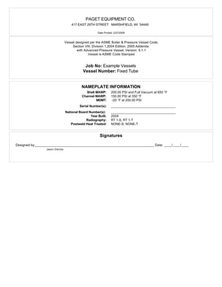
  • 1. PAGET EQUIPMENT CO. 417 EAST 29TH STREET MARSHFIELD, WI 54449 Date Printed: 2/27/2006 Vessel designed per the ASME Boiler & Pressure Vessel Code, Section VIII, Division 1,2004 Edition, 2005 Addenda with Advanced Pressure Vessel, Version: 9.1.1 Vessel is ASME Code Stamped Job No: Example Vessels Vessel Number: Fixed Tube NAMEPLATE INFORMATION Shell MAWP: 200.00 PSI and Full Vacuum at 650 °F Channel MAWP: 150.00 PSI at 350 °F MDMT: -20 °F at 200.00 PSI Serial Number(s): __________________________________ National Board Number(s): __________________________________ Year Built: 2004 Radiography: RT 1-S, RT 1-T Postweld Heat Treated: NONE-S, NONE-T Signatures Designed by:_______________________________________________________________ Date: ____/____/____ Jason Diercks
  • 2. PAGET EQUIPMENT CO. Shell 1 Job No: Example Vessels Vessel Number:Fixed Tube Number: 1 Mark Number: S1 Date Printed: 2/27/2006 Cylindrical Shell Design Information Design Pressure: 200.00 PSI Design Temperature: 650 °F Static Head: 0.00 PSI Joint Efficiency: 100 % Shell Material: SA-516 Gr 70 Factor B Chart: CS-2 Material Stress (hot): 18800 PSI Shell Length: 250.0000 in. Material Stress (cold): 20000 PSI Corrosion Allowance: 0.0625 in. Actual Circumferential Stress: 16970 PSI External Corrosion Allowance: 0.0000 in. Actual Longitudinal Stress: 8385 PSI Inside Diameter (new): 42.0000 in. Inside Diameter (corroded): 42.1250 in. Specific Gravity: 1.00 Shell Surface Area: 232.48 Sq. Ft. Weight of Fluid: 12527.48 lb. Shell Estimated Volume: 1499.57 Gal. Total Flooded Shell Weight: 15466.45 lb. Shell Weight: 2938.97 lb. Minimum Design Metal Temperature Data Min. Temperature Curve: B Pressure at MDMT: 200.00 PSI UCS-66(b) reduction: Yes Minimum Design Metal Temperature: -20 °F UCS-68(c) reduction: No Computed Minimum Temperature: -35 °F External Pressure Data Design Pressure (Pa): 15.00 PSI Design Temperature: 650 °F Dimension L: 125.0000 in. Ext. Minimum t: 0.2783 in. Ext. Nominal t: 0.3125 in. Minimum L/Do: 2.9326 Nominal L/Do: 2.9326 Minimum Do/t: 197.5210 Nominal Do/t: 170.5000 Minimum Factor A: 0.0001770 Nominal Factor A:0.0002268 Minimum Factor B: 2224 PSI Nominal Factor B: 2849 PSI Design Thickness Calculations Longitudinal Stress Calculations per Paragraph UG-27(c)(2) t = PR 2SE + 0.4P = 200.00 * 21.0625 2 * 18800 * 1.00 + 0.4 * 200.00 = 0.1118 + 0.0625 (corrosion) + 0.0000 (ext. corrosion) = minimum of 0.1743 in. Circumferential Stress Calculations per UG-27(c)(1) t = PR SE - 0.6P = 200.00 * 21.0625 18800 * 1.00 - 0.6 * 200.00 = 0.2255 + 0.0625 (corrosion) + 0.0000 (ext. corrosion) = minimum of 0.2880 in. Maximum External Pressure Calculation per Paragraph UG-28 Pa (using nominalt) = 4B 3(Do / t) = 4 * 2849 3 * ( 42.6250 / 0.2500 ) = maximum external pressure of 22.28 PSI Extreme Fiber Elongation Calculation per Paragraph UCS-79 Elongation = 50t Rf = 50 * 0.3125 21.1563 = elongation of 0.74 % Nominal Shell Thickness Selected = 0.3125 in. Advanced Pressure Vessel version: 9.1.1 ©Computer Engineering, Inc. Section VIII, Division 1, 2004 Edition, 2005 AddendaPage 1 of 76
  • 3. PAGET EQUIPMENT CO. 5" Inlet Job No: Example Vessels Vessel Number:Fixed Tube Number: 1 Mark Number: N2 ID Number: 1 Date Printed: 2/27/2006 Nozzle Design Information Design Pressure: 200.00 PSI Design Temperature: 650 °F Static Head: 0.00 PSI Nozzle Efficiency (E): 100 % Nozzle Material: SA-106 Gr B Joint Efficiency (E 1): 1.00 Factor B Chart: CS-2 External Projection: 6.0000 in. Allowable Stress at Design Temperature (Sn): 17100 PSI Internal Projection: 0.0000 in. Allowable Stress at Ambient Temperature: 17100 PSI Inside Corrosion Allowance: 0.0625 in. Correction Factor (F): 1.00 External Corrosion Allowance: 0.0000 in. Passes through a Category A Joint: No Nozzle Pipe Size: 5 Nozzle Pipe Schedule: 80 Nozzle ID (new): 4.8130 in. Nozzle Wall Thickness(new): 0.3750 in. Nozzle ID (corroded): 4.9380 in. Nozzle Wall Thickness(corroded): 0.3125 in. Outer "h" Limit: 0.6250 in. Upper Weld Leg Size(Weld 41): 0.2500 in. Internal "h" Limit: 0.6250 in. Internal Weld Leg Size(Weld 43): 0.0000 in. OD, Limit of Reinforcement: 9.8760 in. Outside Groove Weld Depth: 0.3125 in. Minimum Design Metal Temperature Min. Temp. Curve: B Pressure at MDMT: 0.00 PSI UCS-66(b) reduction: Yes Minimum Design Metal Temperature: -20 °F UCS-68(c) reduction: No Computed Minimum Temperature: -155 °F Reinforcing Pad Information Reinforcing Material: SA-516 Gr 70 Allowable Stress at Design Temperature(Sp): 18800 PSI Allowable Stress at Ambient Temperature: 20000 PSI Reinforcing Plate Thickness(te): 0.2500 in. Repad to Vessel Weld Leg Size(Weld 42): 0.1786 in. OD, Reinforcing Plate(Dp): 8.0000 in. Repad to Nozzle Groove Weld Depth: 0.2500 in. Host Component: Shell 1 - Shell 1 Material: SA-516 Gr 70 Shell wall thickness(new): 0.3125 in. Material Stress(Sv): 18800 PSI Shell wall thickness(corroded): 0.2500 in. Nozzle Detail Information Upper Weld Leg Size(Weld 41): 0.2500 in. Nozzle Wall Thickness(tn): 0.3750 in. Outside Groove Weld Depth: 0.3125 in. Repad to Vessel Weld Leg Size(Weld 42): 0.1786 in. Repad Thickness(te): 0.2500 in. Nozzle passes through the vessel, attached by a groove weld. Pipe Size: 5 Schedule: 80 Nozzle is adequate for UG-45 requirements. Opening is adequately reinforced for Internal Pressure. Opening is adequately reinforced for External Pressure. Weld Strength Paths are adequate. Advanced Pressure Vessel version: 9.1.1 ©Computer Engineering, Inc. Section VIII, Division 1, 2004 Edition, 2005 AddendaPage 2 of 76
  • 4. PAGET EQUIPMENT CO. 5" Inlet Job No: Example Vessels Vessel Number:Fixed Tube Number: 1 Mark Number: N2 ID Number: 1 Date Printed: 2/27/2006 Required Shell Thickness per Paragraph UG-37(a) tr = PR SE - 0.6P = 200.00 * 21.0625 18800 * 1 - 0.6 * 200.00 = 0.2255 in. Nozzle Required Thickness Calculations Required Nozzle Thickness for Internal Pressure per Paragraph UG-37(a) trn = PRn SE - 0.6P = 200.00 * 2.4690 17100 * 1 - 0.6 * 200.00 = 0.0291 in. Required Nozzle Thickness for External Pressure per Paragraph UG-37(a) trn = 3 * Do * Pa 4B = 3 * 5.5630 * 15.00 4 * 3283 = 0.0193 in. Strength Reduction Factors fr1 = Sn Sv = 17100 18800 = 0.9096 fr2 = Sn Sv = 17100 18800 = 0.9096 fr3 = Sn Sv = 17100 18800 = 0.9096 fr4 = Sp Sv = 18800 18800 = 1.0000 UG-45 Thickness Calculations Nozzle Thickness for Pressure Loading (plus corrosion) per Paragraph UG-45(a) t = PRn SE - 0.6P + Ca + ext. Ca = 200.00 * 2.4690 17100 * 1.00 - 0.6 * 200.00 + 0.0625 + 0.0000 = 0.0916 in. Nozzle Thickness for Internal Pressure (plus corrosion) per Paragraph UG-45(b)(1) t = PR SE - 0.6P + Ca + ext. Ca = 200.00 * 21.0625 18800 * 1 - 0.6 * 200.00 + 0.0625 + 0.0000 = 0.2880 in. Nozzle Thickness for External Pressure (plus corrosion) per Paragraph UG-45(b)(2) t = PR SE - 0.6P + Ca + ext. Ca = 15.00 * 21.0625 18800 * 1 - 0.6 * 15.00 + 0.0625 + 0.0000 = 0.1250 in. Minimum Thickness for Internal and External Pressure per Paragraph UG-45(b)(3) t = Greater of the thicknesses determined by UG-45(b)(1) or UG-45(b)(2) = 0.2880 in. Minimum Thickness of Standard Wall Pipe (plus corrosion) per Paragraph UG-45(b)(4) t = minimum thickness of standard wall pipe + Ca + ext. Ca = 0.2882 in. Nozzle Minimum Thickness per Paragraph UG-45(b) t = Smallest of UG-45(b)(3) or UG-45(b)(4) = 0.2880 in. Wall thickness = tn * 0.875(pipe) = 0.3281 is greater than or equal to UG-45 value of 0.2880 Advanced Pressure Vessel version: 9.1.1 ©Computer Engineering, Inc. Section VIII, Division 1, 2004 Edition, 2005 AddendaPage 3 of 76
  • 5. PAGET EQUIPMENT CO. 5" Inlet Job No: Example Vessels Vessel Number:Fixed Tube Number: 1 Mark Number: N2 ID Number: 1 Date Printed: 2/27/2006 Nozzle Reinforcement Calculations Area Required for Internal Pressure A = d tr F + 2 tn tr F (1 - fr1) = (4.9380 * 0.2255 * 1.00) + (2 * 0.3125 * 0.2255 * 1.00 * (1 - 0.9096)) = 1.1263 sq. in. Area Available - Internal Pressure A1 Formula 1= d(E1 t - F tr) - 2tn(E1 t - F tr)(1 - fr1) = 4.9380 * (1.00 * 0.2500 - 1.00 * 0.2255) - 2 * 0.3125 * (1.00 * 0.2500 - 1.00 * 0.2255) * (1 - 0.9096) = 0.1196 sq. in. A1 Formula 2 = 2(t + tn)(E1 t - F tr) - 2tn(E1 t - F tr)(1 - fr1) = 2 * (0.2500 + 0.3125)(1.00 * 0.2500 - 1.00 * 0.2255) - 2 * 0.3125 * (1.00 * 0.2500 - 1.00 * 0.2255) * (1 - 0.9096) = 0.0262 sq. in. A1 = Larger value of A1 Formula 1 and A1 Formula 2 = 0.1196 sq. in. A2 Formula 1= 5(tn - trn) fr2 t = 5(0.3125 - 0.0291) * 0.9096 * 0.2500 = 0.3222 sq. in. A2 Formula 2= 2(tn - trn) fr2 (2.5 tn + te ) = 2(0.3125 - 0.0291) * 0.9096 * (2.5 * 0.3125 + 0.2500) = 0.5317 sq. in. A2 = Smaller value of A2 Formula 1 and A2 Formula 2 = 0.3222 sq. in. A3 = Smaller value of the following : 5 * t * t i * fr2 = 5 * 0.2500 * 0.2500 * 0.9096 = 0.2842 sq. in. 5 * ti * ti * fr2 = 5 * 0.2500 * 0.2500 * 0.9096 = 0.2842 sq. in. 2 * h * ti * fr2 = 2 * 0.0000 * 0.2500 * 0.9096= 0.0000 sq. in. = 0.0000 sq. in. A41 = (leg)Š * fr3 = (0.2500)Š * 0.9096 = 0.0568 sq. in. A42 = (leg)Š * fr4 = (0.1786)Š * 1.0000 = 0.0319 sq. in. A43 = (leg)Š * fr2 = 0 * 0.9096 = 0.0000 sq. in. A5 = (Dp - d - 2tn) te fr4 = (8.0000 - 4.9380 - 2 * 0.3125) * 0.2500 * 1.0000 = 0.6093 sq. in. Area Available (Internal Pressure) = A1 + A2 + A3 + A41 + A42 + A43 + A5 = 1.1398 sq. in., which is greater than A (1.1263) Advanced Pressure Vessel version: 9.1.1 ©Computer Engineering, Inc. Section VIII, Division 1, 2004 Edition, 2005 AddendaPage 4 of 76
  • 6. PAGET EQUIPMENT CO. 5" Inlet Job No: Example Vessels Vessel Number:Fixed Tube Number: 1 Mark Number: N2 ID Number: 1 Date Printed: 2/27/2006 Nozzle Reinforcement Calculations Area Required for External Pressure A = • * (d tr F + 2 tn tr F (1 - fr1)) = • * ((4.9380 * 0.2158 * 1.0) + (2 * 0.3125 * 0.2158 * 1.0 * (1 - 0.9096))) = 0.5389 sq. in. Area Available - External Pressure A1 Formula 1= d(E1 t - F tr) - 2tn(E1 t - F tr)(1 - fr1) = 4.9380 * (1.00 * 0.2500 - 1.00 * 0.2158) - 2 * 0.3125 * (1.00 * 0.2500 - 1.00 * 0.2158) * (1 - 0.9096) = 0.1669 sq. in. A1 Formula 2 = 2(t + tn)(E1 t - F tr) - 2tn(E1 t - F tr)(1 - fr1) = 2 * (0.2500 + 0.3125)(1.00 * 0.2500 - 1.00 * 0.2158) - 2 * 0.3125 * (1.00 * 0.2500 - 1.00 * 0.2158) * (1 - 0.9096) = 0.0365 sq. in. A1 = Larger value of A1 Formula 1 and A1 Formula 2 = 0.1669 sq. in. A2 Formula 1= 5(tn - trn) fr2 t = 5(0.3125 - 0.0193) * 0.9096 * 0.2500 = 0.3334 sq. in. A2 Formula 2= 2(tn - trn) fr2 (2.5 tn + te ) = 2(0.3125 - 0.0193) * 0.9096 * (2.5 * 0.3125 + 0.2500) = 0.5500 sq. in. A2 = Smaller value of A2 Formula 1 and A2 Formula 2 = 0.3334 sq. in. A3 = Smaller value of the following : 5 * t * t i * fr2 = 5 * 0.2500 * 0.2500 * 0.9096 = 0.2842 sq. in. 5 * ti * ti * fr2 = 5 * 0.2500 * 0.2500 * 0.9096 = 0.2842 sq. in. 2 * h * ti * fr2 = 2 * 0.0000 * 0.2500 * 0.9096= 0.0000 sq. in. = 0.0000 sq. in. A41 = (leg)Š * fr3 = (0.2500)Š * 0.9096 = 0.0568 sq. in. A42 = (leg)Š * fr4 = (0.1786)Š * 1.0000 = 0.0319 sq. in. A43 = (leg)Š * fr2 = 0 * 0.9096 = 0.0000 sq. in. A5 = (Dp - d - 2tn) te fr4 = (8.0000 - 4.9380 - 2 * 0.3125) * 0.2500 * 1.0000 = 0.6093 sq. in. Area Available (External Pressure) = A1 + A2 + A3 + A41 + A42 + A43 + A5 = 1.1983 sq. in., which is greater than A (0.5389) Advanced Pressure Vessel version: 9.1.1 ©Computer Engineering, Inc. Section VIII, Division 1, 2004 Edition, 2005 AddendaPage 5 of 76
  • 7. PAGET EQUIPMENT CO. 5" Inlet Job No: Example Vessels Vessel Number:Fixed Tube Number: 1 Mark Number: N2 ID Number: 1 Date Printed: 2/27/2006 Nozzle Weld Strength Calculations Attachment Weld Strength per Paragraph UW-16 Weld 41 tmin = smaller of 0.75, te, or tn = smaller of 0.75, 0.2500, or 0.3125 = 0.2500 in. Weld 41 Leg min. = (smaller of 0.25 or (tmin * 0.7)) + ext. CA 0.7 = 0.1750 0.7 = 0.2500 in. Weld 41, actual weld leg = 0.2500 in. Weld 42 tmin = smaller of 0.75, t, or te = smaller of 0.75, 0.2500, or 0.2500 = 0.2500 in. Weld 42 Leg min. = 0.5 * tmin + ext. CA 0.7 = 0.5 * 0.2500 + 0.0000 0.7 = 0.1786 in. Weld 42, actual weld leg = 0.1786 in. Unit Stresses per Paragraphs UG-45(c) and UW-15 Nozzle wall in shear = 0.70 * Sn = 0.70 * 17100 = 11970 PSI Upper fillet, Weld 41, in shear = 0.49 * Material Stress = 0.49 * 17100 = 8379 PSI Vessel groove weld, in tension = 0.74 * Material Stress = 0.74 * 17100 = 12654 PSI Outer fillet, Weld 42, in shear = 0.49 * Material Stress = 0.49 * 18800 = 9212 PSI Repad groove weld, in tension = 0.74 * Material Stress = 0.74 * 17100 = 12654 PSI Strength of Connection Elements Nozzle wall in shear = • * m * mean nozzle diameter * tn * Nozzle wall in shear unit stress = • * m * 5.2505 * 0.3125 * 11970 = 30800 lb. Upper fillet in shear = • * m * Nozzle OD * weld leg * upper fillet in shear unit stress= • * m * 5.5630 * 0.2500 * 8379 = 18300 lb. Groove Weld in Tension = • * m * Nozzle OD * groove depth * groove weld tension unit stress = • * m * 5.5630 * 0.2500 * 12654 = 27600 lb. Outer fillet in shear = • * m * Plate OD * weld leg * outer fillet in shear unit stress= • * m * 8.0000 * 0.1786 * 9212 = 20700 lb. Repad groove weld = • * m * Nozzle OD * Groove Depth * repad groove weld in tension unit stress = • * m * 5.5630 * 0.2500 * 12654 = 27600 lb. Load to be carried by welds, per UG-41(b)(1) and Fig. UG-41.1 sketch (a) W = [A - A1 + 2 tn fr1(E1t - Ftr)] Sv = [1.1263 - 0.1196 + 2 * 0.3125 * 0.9096 * (1.00 * 0.2500 - 1.0000 * 0.2255)] * 18800 = 19200 lb. W1-1 = (A2 + A5 + A41 + A42) * Sv = (0.3222 + 0.6093 + 0.0568 + 0.0319) * 18800 = 19200 lb. W2-2 = (A2 + A3 + A41 + A43 + 2 tn t fr1) Sv = (0.3222 + 0.0000 + 0.0568 + 0.0000 + 2 * 0.3125 * 0.2500 * 0.9096) * 18800 = 9800 lb. W3-3 = (A2 + A3 + A5 + A41 + A42 + A43 + 2 tn t fr1) * Sv = (0.3222 + 0.0000 + 0.6093 + 0.0568 + 0.0319 + 0.0000 + 2 * 0.3125 * 0.2500 * 0.9096) * 18800 = 21900 lb. Check Strength Paths Path 1-1 = Outer fillet in shear + Nozzle wall in shear = 20700 + 30800 = 51500 lb. Path 2-2 = Upper fillet in shear + Repad groove weld + Groove weld in tension + Inner fillet in shear = 18300 + 27600 + 27600 + 0 = 73500 lb. Path 3-3 = Outer fillet in shear + Inner fillet in shear + Groove weld in tension = 20700 + 0 + 27600 = 48300 lb. Advanced Pressure Vessel version: 9.1.1 ©Computer Engineering, Inc. Section VIII, Division 1, 2004 Edition, 2005 AddendaPage 6 of 76
  • 8. PAGET EQUIPMENT CO. 5" Inlet Job No: Example Vessels Vessel Number:Fixed Tube Number: 1 Mark Number: N2 ID Number: 1 Date Printed: 2/27/2006 Plate Strength = A5 * Sp = 0.6093 * 18800 = 11455 lb. Outer fillet weld strength(20700) is greater than plate strength(11455). Advanced Pressure Vessel version: 9.1.1 ©Computer Engineering, Inc. Section VIII, Division 1, 2004 Edition, 2005 AddendaPage 7 of 76
  • 9. PAGET EQUIPMENT CO. 5" Outlet Job No: Example Vessels Vessel Number:Fixed Tube Number: 2 Mark Number: N2 ID Number: 2 Date Printed: 2/27/2006 Nozzle Design Information Design Pressure: 200.00 PSI Design Temperature: 650 °F Static Head: 0.00 PSI Nozzle Efficiency (E): 100 % Nozzle Material: SA-106 Gr B Joint Efficiency (E 1): 1.00 Factor B Chart: CS-2 External Projection: 6.0000 in. Allowable Stress at Design Temperature (Sn): 17100 PSI Internal Projection: 0.0000 in. Allowable Stress at Ambient Temperature: 17100 PSI Inside Corrosion Allowance: 0.0625 in. Correction Factor (F): 1.00 External Corrosion Allowance: 0.0000 in. Passes through a Category A Joint: No Nozzle Pipe Size: 5 Nozzle Pipe Schedule: 80 Nozzle ID (new): 4.8130 in. Nozzle Wall Thickness(new): 0.3750 in. Nozzle ID (corroded): 4.9380 in. Nozzle Wall Thickness(corroded): 0.3125 in. Outer "h" Limit: 0.6250 in. Upper Weld Leg Size(Weld 41): 0.2500 in. Internal "h" Limit: 0.6250 in. Internal Weld Leg Size(Weld 43): 0.0000 in. OD, Limit of Reinforcement: 9.8760 in. Outside Groove Weld Depth: 0.3125 in. Minimum Design Metal Temperature Min. Temp. Curve: B Pressure at MDMT: 0.00 PSI UCS-66(b) reduction: Yes Minimum Design Metal Temperature: -20 °F UCS-68(c) reduction: No Computed Minimum Temperature: -155 °F Reinforcing Pad Information Reinforcing Material: SA-516 Gr 70 Allowable Stress at Design Temperature(Sp): 18800 PSI Allowable Stress at Ambient Temperature: 20000 PSI Reinforcing Plate Thickness(te): 0.2500 in. Repad to Vessel Weld Leg Size(Weld 42): 0.1786 in. OD, Reinforcing Plate(Dp): 8.0000 in. Repad to Nozzle Groove Weld Depth: 0.2500 in. Host Component: Shell 1 - Shell 1 Material: SA-516 Gr 70 Shell wall thickness(new): 0.3125 in. Material Stress(Sv): 18800 PSI Shell wall thickness(corroded): 0.2500 in. Nozzle Detail Information Upper Weld Leg Size(Weld 41): 0.2500 in. Nozzle Wall Thickness(tn): 0.3750 in. Outside Groove Weld Depth: 0.3125 in. Repad to Vessel Weld Leg Size(Weld 42): 0.1786 in. Repad Thickness(te): 0.2500 in. Nozzle passes through the vessel, attached by a groove weld. Pipe Size: 5 Schedule: 80 Nozzle is adequate for UG-45 requirements. Opening is adequately reinforced for Internal Pressure. Opening is adequately reinforced for External Pressure. Weld Strength Paths are adequate. Advanced Pressure Vessel version: 9.1.1 ©Computer Engineering, Inc. Section VIII, Division 1, 2004 Edition, 2005 AddendaPage 8 of 76
  • 10. PAGET EQUIPMENT CO. 5" Outlet Job No: Example Vessels Vessel Number:Fixed Tube Number: 2 Mark Number: N2 ID Number: 2 Date Printed: 2/27/2006 Required Shell Thickness per Paragraph UG-37(a) tr = PR SE - 0.6P = 200.00 * 21.0625 18800 * 1 - 0.6 * 200.00 = 0.2255 in. Nozzle Required Thickness Calculations Required Nozzle Thickness for Internal Pressure per Paragraph UG-37(a) trn = PRn SE - 0.6P = 200.00 * 2.4690 17100 * 1 - 0.6 * 200.00 = 0.0291 in. Required Nozzle Thickness for External Pressure per Paragraph UG-37(a) trn = 3 * Do * Pa 4B = 3 * 5.5630 * 15.00 4 * 3283 = 0.0193 in. Strength Reduction Factors fr1 = Sn Sv = 17100 18800 = 0.9096 fr2 = Sn Sv = 17100 18800 = 0.9096 fr3 = Sn Sv = 17100 18800 = 0.9096 fr4 = Sp Sv = 18800 18800 = 1.0000 UG-45 Thickness Calculations Nozzle Thickness for Pressure Loading (plus corrosion) per Paragraph UG-45(a) t = PRn SE - 0.6P + Ca + ext. Ca = 200.00 * 2.4690 17100 * 1.00 - 0.6 * 200.00 + 0.0625 + 0.0000 = 0.0916 in. Nozzle Thickness for Internal Pressure (plus corrosion) per Paragraph UG-45(b)(1) t = PR SE - 0.6P + Ca + ext. Ca = 200.00 * 21.0625 18800 * 1 - 0.6 * 200.00 + 0.0625 + 0.0000 = 0.2880 in. Nozzle Thickness for External Pressure (plus corrosion) per Paragraph UG-45(b)(2) t = PR SE - 0.6P + Ca + ext. Ca = 15.00 * 21.0625 18800 * 1 - 0.6 * 15.00 + 0.0625 + 0.0000 = 0.1250 in. Minimum Thickness for Internal and External Pressure per Paragraph UG-45(b)(3) t = Greater of the thicknesses determined by UG-45(b)(1) or UG-45(b)(2) = 0.2880 in. Minimum Thickness of Standard Wall Pipe (plus corrosion) per Paragraph UG-45(b)(4) t = minimum thickness of standard wall pipe + Ca + ext. Ca = 0.2882 in. Nozzle Minimum Thickness per Paragraph UG-45(b) t = Smallest of UG-45(b)(3) or UG-45(b)(4) = 0.2880 in. Wall thickness = tn * 0.875(pipe) = 0.3281 is greater than or equal to UG-45 value of 0.2880 Advanced Pressure Vessel version: 9.1.1 ©Computer Engineering, Inc. Section VIII, Division 1, 2004 Edition, 2005 AddendaPage 9 of 76
  • 11. PAGET EQUIPMENT CO. 5" Outlet Job No: Example Vessels Vessel Number:Fixed Tube Number: 2 Mark Number: N2 ID Number: 2 Date Printed: 2/27/2006 Nozzle Reinforcement Calculations Area Required for Internal Pressure A = d tr F + 2 tn tr F (1 - fr1) = (4.9380 * 0.2255 * 1.00) + (2 * 0.3125 * 0.2255 * 1.00 * (1 - 0.9096)) = 1.1263 sq. in. Area Available - Internal Pressure A1 Formula 1= d(E1 t - F tr) - 2tn(E1 t - F tr)(1 - fr1) = 4.9380 * (1.00 * 0.2500 - 1.00 * 0.2255) - 2 * 0.3125 * (1.00 * 0.2500 - 1.00 * 0.2255) * (1 - 0.9096) = 0.1196 sq. in. A1 Formula 2 = 2(t + tn)(E1 t - F tr) - 2tn(E1 t - F tr)(1 - fr1) = 2 * (0.2500 + 0.3125)(1.00 * 0.2500 - 1.00 * 0.2255) - 2 * 0.3125 * (1.00 * 0.2500 - 1.00 * 0.2255) * (1 - 0.9096) = 0.0262 sq. in. A1 = Larger value of A1 Formula 1 and A1 Formula 2 = 0.1196 sq. in. A2 Formula 1= 5(tn - trn) fr2 t = 5(0.3125 - 0.0291) * 0.9096 * 0.2500 = 0.3222 sq. in. A2 Formula 2= 2(tn - trn) fr2 (2.5 tn + te ) = 2(0.3125 - 0.0291) * 0.9096 * (2.5 * 0.3125 + 0.2500) = 0.5317 sq. in. A2 = Smaller value of A2 Formula 1 and A2 Formula 2 = 0.3222 sq. in. A3 = Smaller value of the following : 5 * t * t i * fr2 = 5 * 0.2500 * 0.2500 * 0.9096 = 0.2842 sq. in. 5 * ti * ti * fr2 = 5 * 0.2500 * 0.2500 * 0.9096 = 0.2842 sq. in. 2 * h * ti * fr2 = 2 * 0.0000 * 0.2500 * 0.9096= 0.0000 sq. in. = 0.0000 sq. in. A41 = (leg)Š * fr3 = (0.2500)Š * 0.9096 = 0.0568 sq. in. A42 = (leg)Š * fr4 = (0.1786)Š * 1.0000 = 0.0319 sq. in. A43 = (leg)Š * fr2 = 0 * 0.9096 = 0.0000 sq. in. A5 = (Dp - d - 2tn) te fr4 = (8.0000 - 4.9380 - 2 * 0.3125) * 0.2500 * 1.0000 = 0.6093 sq. in. Area Available (Internal Pressure) = A1 + A2 + A3 + A41 + A42 + A43 + A5 = 1.1398 sq. in., which is greater than A (1.1263) Advanced Pressure Vessel version: 9.1.1 ©Computer Engineering, Inc. Section VIII, Division 1, 2004 Edition, 2005 AddendaPage 10 of 76
  • 12. PAGET EQUIPMENT CO. 5" Outlet Job No: Example Vessels Vessel Number:Fixed Tube Number: 2 Mark Number: N2 ID Number: 2 Date Printed: 2/27/2006 Nozzle Reinforcement Calculations Area Required for External Pressure A = • * (d tr F + 2 tn tr F (1 - fr1)) = • * ((4.9380 * 0.2158 * 1.0) + (2 * 0.3125 * 0.2158 * 1.0 * (1 - 0.9096))) = 0.5389 sq. in. Area Available - External Pressure A1 Formula 1= d(E1 t - F tr) - 2tn(E1 t - F tr)(1 - fr1) = 4.9380 * (1.00 * 0.2500 - 1.00 * 0.2158) - 2 * 0.3125 * (1.00 * 0.2500 - 1.00 * 0.2158) * (1 - 0.9096) = 0.1669 sq. in. A1 Formula 2 = 2(t + tn)(E1 t - F tr) - 2tn(E1 t - F tr)(1 - fr1) = 2 * (0.2500 + 0.3125)(1.00 * 0.2500 - 1.00 * 0.2158) - 2 * 0.3125 * (1.00 * 0.2500 - 1.00 * 0.2158) * (1 - 0.9096) = 0.0365 sq. in. A1 = Larger value of A1 Formula 1 and A1 Formula 2 = 0.1669 sq. in. A2 Formula 1= 5(tn - trn) fr2 t = 5(0.3125 - 0.0193) * 0.9096 * 0.2500 = 0.3334 sq. in. A2 Formula 2= 2(tn - trn) fr2 (2.5 tn + te ) = 2(0.3125 - 0.0193) * 0.9096 * (2.5 * 0.3125 + 0.2500) = 0.5500 sq. in. A2 = Smaller value of A2 Formula 1 and A2 Formula 2 = 0.3334 sq. in. A3 = Smaller value of the following : 5 * t * t i * fr2 = 5 * 0.2500 * 0.2500 * 0.9096 = 0.2842 sq. in. 5 * ti * ti * fr2 = 5 * 0.2500 * 0.2500 * 0.9096 = 0.2842 sq. in. 2 * h * ti * fr2 = 2 * 0.0000 * 0.2500 * 0.9096= 0.0000 sq. in. = 0.0000 sq. in. A41 = (leg)Š * fr3 = (0.2500)Š * 0.9096 = 0.0568 sq. in. A42 = (leg)Š * fr4 = (0.1786)Š * 1.0000 = 0.0319 sq. in. A43 = (leg)Š * fr2 = 0 * 0.9096 = 0.0000 sq. in. A5 = (Dp - d - 2tn) te fr4 = (8.0000 - 4.9380 - 2 * 0.3125) * 0.2500 * 1.0000 = 0.6093 sq. in. Area Available (External Pressure) = A1 + A2 + A3 + A41 + A42 + A43 + A5 = 1.1983 sq. in., which is greater than A (0.5389) Advanced Pressure Vessel version: 9.1.1 ©Computer Engineering, Inc. Section VIII, Division 1, 2004 Edition, 2005 AddendaPage 11 of 76
  • 13. PAGET EQUIPMENT CO. 5" Outlet Job No: Example Vessels Vessel Number:Fixed Tube Number: 2 Mark Number: N2 ID Number: 2 Date Printed: 2/27/2006 Nozzle Weld Strength Calculations Attachment Weld Strength per Paragraph UW-16 Weld 41 tmin = smaller of 0.75, te, or tn = smaller of 0.75, 0.2500, or 0.3125 = 0.2500 in. Weld 41 Leg min. = (smaller of 0.25 or (tmin * 0.7)) + ext. CA 0.7 = 0.1750 0.7 = 0.2500 in. Weld 41, actual weld leg = 0.2500 in. Weld 42 tmin = smaller of 0.75, t, or te = smaller of 0.75, 0.2500, or 0.2500 = 0.2500 in. Weld 42 Leg min. = 0.5 * tmin + ext. CA 0.7 = 0.5 * 0.2500 + 0.0000 0.7 = 0.1786 in. Weld 42, actual weld leg = 0.1786 in. Unit Stresses per Paragraphs UG-45(c) and UW-15 Nozzle wall in shear = 0.70 * Sn = 0.70 * 17100 = 11970 PSI Upper fillet, Weld 41, in shear = 0.49 * Material Stress = 0.49 * 17100 = 8379 PSI Vessel groove weld, in tension = 0.74 * Material Stress = 0.74 * 17100 = 12654 PSI Outer fillet, Weld 42, in shear = 0.49 * Material Stress = 0.49 * 18800 = 9212 PSI Repad groove weld, in tension = 0.74 * Material Stress = 0.74 * 17100 = 12654 PSI Strength of Connection Elements Nozzle wall in shear = • * m * mean nozzle diameter * tn * Nozzle wall in shear unit stress = • * m * 5.2505 * 0.3125 * 11970 = 30800 lb. Upper fillet in shear = • * m * Nozzle OD * weld leg * upper fillet in shear unit stress= • * m * 5.5630 * 0.2500 * 8379 = 18300 lb. Groove Weld in Tension = • * m * Nozzle OD * groove depth * groove weld tension unit stress = • * m * 5.5630 * 0.2500 * 12654 = 27600 lb. Outer fillet in shear = • * m * Plate OD * weld leg * outer fillet in shear unit stress= • * m * 8.0000 * 0.1786 * 9212 = 20700 lb. Repad groove weld = • * m * Nozzle OD * Groove Depth * repad groove weld in tension unit stress = • * m * 5.5630 * 0.2500 * 12654 = 27600 lb. Load to be carried by welds, per UG-41(b)(1) and Fig. UG-41.1 sketch (a) W = [A - A1 + 2 tn fr1(E1t - Ftr)] Sv = [1.1263 - 0.1196 + 2 * 0.3125 * 0.9096 * (1.00 * 0.2500 - 1.0000 * 0.2255)] * 18800 = 19200 lb. W1-1 = (A2 + A5 + A41 + A42) * Sv = (0.3222 + 0.6093 + 0.0568 + 0.0319) * 18800 = 19200 lb. W2-2 = (A2 + A3 + A41 + A43 + 2 tn t fr1) Sv = (0.3222 + 0.0000 + 0.0568 + 0.0000 + 2 * 0.3125 * 0.2500 * 0.9096) * 18800 = 9800 lb. W3-3 = (A2 + A3 + A5 + A41 + A42 + A43 + 2 tn t fr1) * Sv = (0.3222 + 0.0000 + 0.6093 + 0.0568 + 0.0319 + 0.0000 + 2 * 0.3125 * 0.2500 * 0.9096) * 18800 = 21900 lb. Check Strength Paths Path 1-1 = Outer fillet in shear + Nozzle wall in shear = 20700 + 30800 = 51500 lb. Path 2-2 = Upper fillet in shear + Repad groove weld + Groove weld in tension + Inner fillet in shear = 18300 + 27600 + 27600 + 0 = 73500 lb. Path 3-3 = Outer fillet in shear + Inner fillet in shear + Groove weld in tension = 20700 + 0 + 27600 = 48300 lb. Advanced Pressure Vessel version: 9.1.1 ©Computer Engineering, Inc. Section VIII, Division 1, 2004 Edition, 2005 AddendaPage 12 of 76
  • 14. PAGET EQUIPMENT CO. 5" Outlet Job No: Example Vessels Vessel Number:Fixed Tube Number: 2 Mark Number: N2 ID Number: 2 Date Printed: 2/27/2006 Plate Strength = A5 * Sp = 0.6093 * 18800 = 11455 lb. Outer fillet weld strength(20700) is greater than plate strength(11455). Advanced Pressure Vessel version: 9.1.1 ©Computer Engineering, Inc. Section VIII, Division 1, 2004 Edition, 2005 AddendaPage 13 of 76
  • 15. PAGET EQUIPMENT CO. 3.5" Inlet Job No: Example Vessels Vessel Number:Fixed Tube Number: 4 Mark Number: N5 ID Number: 4 Date Printed: 2/27/2006 Nozzle Design Information Design Pressure: 150.00 PSI Design Temperature: 350 °F Static Head: 0.00 PSI Nozzle Efficiency (E): 100 % Nozzle Material: SA-106 Gr B Joint Efficiency (E 1): 1.00 Factor B Chart: CS-2 External Projection: 6.0000 in. Allowable Stress at Design Temperature (Sn): 17100 PSI Internal Projection: 0.0000 in. Allowable Stress at Ambient Temperature: 17100 PSI Inside Corrosion Allowance: 0.0625 in. Correction Factor (F): 1.00 External Corrosion Allowance: 0.0000 in. Passes through a Category A Joint: No Nozzle Pipe Size: 3.5 Nozzle Pipe Schedule: 80 Nozzle ID (new): 3.3640 in. Nozzle Wall Thickness(new): 0.3180 in. Nozzle ID (corroded): 3.4890 in. Nozzle Wall Thickness(corroded): 0.2555 in. Outer "h" Limit: 0.4688 in. Upper Weld Leg Size(Weld 41): 0.1875 in. Internal "h" Limit: 0.4688 in. Internal Weld Leg Size(Weld 43): 0.0000 in. OD, Limit of Reinforcement: 6.9780 in. Outside Groove Weld Depth: 0.2500 in. Minimum Design Metal Temperature Min. Temp. Curve: B Pressure at MDMT: 0.00 PSI UCS-66(b) reduction: Yes Minimum Design Metal Temperature: -20 °F UCS-68(c) reduction: No Computed Minimum Temperature: -155 °F Reinforcing Pad Information Reinforcing Material: SA-516 Gr 70 Allowable Stress at Design Temperature(Sp): 20000 PSI Allowable Stress at Ambient Temperature: 20000 PSI Reinforcing Plate Thickness(te): 0.1875 in. Repad to Vessel Weld Leg Size(Weld 42): 0.1339 in. OD, Reinforcing Plate(Dp): 6.0000 in. Repad to Nozzle Groove Weld Depth: 0.1875 in. Host Component: 2 - Left Channel Shell Material: SA-516 Gr 70 Channel wall thickness(new): 0.2500 in. Material Stress(Sv): 20000 PSI Channel wall thickness(corroded): 0.1875 in. Nozzle Detail Information Upper Weld Leg Size(Weld 41): 0.1875 in. Nozzle Wall Thickness(tn): 0.3180 in. Outside Groove Weld Depth: 0.2500 in. Repad to Vessel Weld Leg Size(Weld 42): 0.1339 in. Repad Thickness(te): 0.1875 in. Nozzle passes through the vessel, attached by a groove weld. Pipe Size: 3.5 Schedule: 80 Nozzle is adequate for UG-45 requirements. Opening is adequately reinforced for Internal Pressure. Opening is adequately reinforced for External Pressure. Reinforcement calculations are not required per UG-36(c)(3)(a)See Uw-14 for exceptions. Weld Strength Paths are adequate. Advanced Pressure Vessel version: 9.1.1 ©Computer Engineering, Inc. Section VIII, Division 1, 2004 Edition, 2005 AddendaPage 14 of 76
  • 16. PAGET EQUIPMENT CO. 3.5" Inlet Job No: Example Vessels Vessel Number:Fixed Tube Number: 4 Mark Number: N5 ID Number: 4 Date Printed: 2/27/2006 Required Channel Thickness per Paragraph UG-37(a) tr = PR SE - 0.6P = 150.00 * 21.0625 20000 * 1 - 0.6 * 150.00 = 0.1587 in. Nozzle Required Thickness Calculations Required Nozzle Thickness for Internal Pressure per Paragraph UG-37(a) trn = PRn SE - 0.6P = 150.00 * 1.7445 17100 * 1 - 0.6 * 150.00 = 0.0154 in. Required Nozzle Thickness for External Pressure per Paragraph UG-37(a) trn = 3 * Do * Pa 4B = 3 * 4.0000 * 15.00 4 * 2931 = 0.0154 in. Strength Reduction Factors fr1 = Sn Sv = 17100 20000 = 0.8550 fr2 = Sn Sv = 17100 20000 = 0.8550 fr3 = Sn Sv = 17100 20000 = 0.8550 fr4 = Sp Sv = 20000 20000 = 1.0000 UG-45 Thickness Calculations Nozzle Thickness for Pressure Loading (plus corrosion) per Paragraph UG-45(a) t = PRn SE - 0.6P + Ca + ext. Ca = 150.00 * 1.7445 17100 * 1.00 - 0.6 * 150.00 + 0.0625 + 0.0000 = 0.0779 in. Nozzle Thickness for Internal Pressure (plus corrosion) per Paragraph UG-45(b)(1) t = PR SE - 0.6P + Ca + ext. Ca = 150.00 * 21.0625 20000 * 1 - 0.6 * 150.00 + 0.0625 + 0.0000 = 0.2212 in. Nozzle Thickness for External Pressure (plus corrosion) per Paragraph UG-45(b)(2) t = PR SE - 0.6P + Ca + ext. Ca = 15.00 * 21.0625 20000 * 1 - 0.6 * 15.00 + 0.0625 + 0.0000 = 0.1250 in. Minimum Thickness for Internal and External Pressure per Paragraph UG-45(b)(3) t = Greater of the thicknesses determined by UG-45(b)(1) or UG-45(b)(2) = 0.2212 in. Minimum Thickness of Standard Wall Pipe (plus corrosion) per Paragraph UG-45(b)(4) t = minimum thickness of standard wall pipe + Ca + ext. Ca = 0.2602 in. Nozzle Minimum Thickness per Paragraph UG-45(b) t = Smallest of UG-45(b)(3) or UG-45(b)(4) = 0.2212 in. Wall thickness = tn * 0.875(pipe) = 0.2782 is greater than or equal to UG-45 value of 0.2212 Advanced Pressure Vessel version: 9.1.1 ©Computer Engineering, Inc. Section VIII, Division 1, 2004 Edition, 2005 AddendaPage 15 of 76
  • 17. PAGET EQUIPMENT CO. 3.5" Inlet Job No: Example Vessels Vessel Number:Fixed Tube Number: 4 Mark Number: N5 ID Number: 4 Date Printed: 2/27/2006 Nozzle Weld Strength Calculations Attachment Weld Strength per Paragraph UW-16 Weld 41 tmin = smaller of 0.75, te, or tn = smaller of 0.75, 0.1875, or 0.2555 = 0.1875 in. Weld 41 Leg min. = (smaller of 0.25 or (tmin * 0.7)) + ext. CA 0.7 = 0.1313 0.7 = 0.1875 in. Weld 41, actual weld leg = 0.1875 in. Weld 42 tmin = smaller of 0.75, t, or te = smaller of 0.75, 0.1875, or 0.1875 = 0.1875 in. Weld 42 Leg min. = 0.5 * tmin + ext. CA 0.7 = 0.5 * 0.1875 + 0.0000 0.7 = 0.1339 in. Weld 42, actual weld leg = 0.1339 in. Unit Stresses per Paragraphs UG-45(c) and UW-15 Nozzle wall in shear = 0.70 * Sn = 0.70 * 17100 = 11970 PSI Upper fillet, Weld 41, in shear = 0.49 * Material Stress = 0.49 * 17100 = 8379 PSI Vessel groove weld, in tension = 0.74 * Material Stress = 0.74 * 17100 = 12654 PSI Outer fillet, Weld 42, in shear = 0.49 * Material Stress = 0.49 * 20000 = 9800 PSI Repad groove weld, in tension = 0.74 * Material Stress = 0.74 * 17100 = 12654 PSI Strength of Connection Elements Nozzle wall in shear = • * m * mean nozzle diameter * tn * Nozzle wall in shear unit stress = • * m * 3.7445 * 0.2555 * 11970 = 18000 lb. Upper fillet in shear = • * m * Nozzle OD * weld leg * upper fillet in shear unit stress= • * m * 4.0000 * 0.1875 * 8379 = 9870 lb. Groove Weld in Tension = • * m * Nozzle OD * groove depth * groove weld tension unit stress = • * m * 4.0000 * 0.1875 * 12654 = 14900 lb. Outer fillet in shear = • * m * Plate OD * weld leg * outer fillet in shear unit stress= • * m * 6.0000 * 0.1339 * 9800 = 12400 lb. Repad groove weld = • * m * Nozzle OD * Groove Depth * repad groove weld in tension unit stress = • * m * 4.0000 * 0.1875 * 12654 = 14900 lb. Load to be carried by welds, per UG-41(b)(1) and Fig. UG-41.1 sketch (a) W = [A - A1 + 2 tn fr1(E1t - Ftr)] Sv = [0.5655 - 0.0983 + 2 * 0.2555 * 0.8550 * (1.00 * 0.1875 - 1.0000 * 0.1587)] * 20000 = 9600 lb. W1-1 = (A2 + A5 + A41 + A42) * Sv = (0.1925 + 0.3750 + 0.0301 + 0.0179) * 20000 = 12300 lb. W2-2 = (A2 + A3 + A41 + A43 + 2 tn t fr1) Sv = (0.1925 + 0.0000 + 0.0301 + 0.0000 + 2 * 0.2555 * 0.1875 * 0.8550) * 20000 = 6090 lb. W3-3 = (A2 + A3 + A5 + A41 + A42 + A43 + 2 tn t fr1) * Sv = (0.1925 + 0.0000 + 0.3750 + 0.0301 + 0.0179 + 0.0000 + 2 * 0.2555 * 0.1875 * 0.8550) * 20000 = 13900 lb. Check Strength Paths Path 1-1 = Outer fillet in shear + Nozzle wall in shear = 12400 + 18000 = 30400 lb. Path 2-2 = Upper fillet in shear + Repad groove weld + Groove weld in tension + Inner fillet in shear = 9870 + 14900 + 14900 + 0 = 39670 lb. Path 3-3 = Outer fillet in shear + Inner fillet in shear + Groove weld in tension = 12400 + 0 + 14900 = 27300 lb. Advanced Pressure Vessel version: 9.1.1 ©Computer Engineering, Inc. Section VIII, Division 1, 2004 Edition, 2005 AddendaPage 16 of 76
  • 18. PAGET EQUIPMENT CO. 3.5" Inlet Job No: Example Vessels Vessel Number:Fixed Tube Number: 4 Mark Number: N5 ID Number: 4 Date Printed: 2/27/2006 Plate Strength = A5 * Sp = 0.3750 * 20000 = 7500 lb. Outer fillet weld strength(12400) is greater than plate strength(7500). Advanced Pressure Vessel version: 9.1.1 ©Computer Engineering, Inc. Section VIII, Division 1, 2004 Edition, 2005 AddendaPage 17 of 76
  • 19. PAGET EQUIPMENT CO. 3.5" Outlet Job No: Example Vessels Vessel Number:Fixed Tube Number: 6 Mark Number: N3 ID Number: 6 Date Printed: 2/27/2006 Nozzle Design Information Design Pressure: 150.00 PSI Design Temperature: 350 °F Static Head: 0.00 PSI Nozzle Efficiency (E): 100 % Nozzle Material: SA-106 Gr B Joint Efficiency (E 1): 1.00 Factor B Chart: CS-2 External Projection: 6.0000 in. Allowable Stress at Design Temperature (Sn): 17100 PSI Internal Projection: 0.0000 in. Allowable Stress at Ambient Temperature: 17100 PSI Inside Corrosion Allowance: 0.0625 in. Correction Factor (F): 1.00 External Corrosion Allowance: 0.0000 in. Passes through a Category A Joint: No Nozzle Pipe Size: 3.5 Nozzle Pipe Schedule: 80 Nozzle ID (new): 3.3640 in. Nozzle Wall Thickness(new): 0.3180 in. Nozzle ID (corroded): 3.4890 in. Nozzle Wall Thickness(corroded): 0.2555 in. Outer "h" Limit: 0.4688 in. Upper Weld Leg Size(Weld 41): 0.1875 in. Internal "h" Limit: 0.4688 in. Internal Weld Leg Size(Weld 43): 0.0000 in. OD, Limit of Reinforcement: 6.9780 in. Outside Groove Weld Depth: 0.2500 in. Minimum Design Metal Temperature Min. Temp. Curve: B Pressure at MDMT: 200.00 PSI UCS-66(b) reduction: Yes Minimum Design Metal Temperature: -20 °F UCS-68(c) reduction: No Computed Minimum Temperature: -155 °F Reinforcing Pad Information Reinforcing Material: SA-516 Gr 70 Allowable Stress at Design Temperature(Sp): 20000 PSI Allowable Stress at Ambient Temperature: 20000 PSI Reinforcing Plate Thickness(te): 0.1875 in. Repad to Vessel Weld Leg Size(Weld 42): 0.1339 in. OD, Reinforcing Plate(Dp): 6.0000 in. Repad to Nozzle Groove Weld Depth: 0.1875 in. Host Component: 1 - Right Channel Shell Material: SA-516 Gr 70 Channel wall thickness(new): 0.2500 in. Material Stress(Sv): 20000 PSI Channel wall thickness(corroded): 0.1875 in. Nozzle Detail Information Upper Weld Leg Size(Weld 41): 0.1875 in. Nozzle Wall Thickness(tn): 0.3180 in. Outside Groove Weld Depth: 0.2500 in. Repad to Vessel Weld Leg Size(Weld 42): 0.1339 in. Repad Thickness(te): 0.1875 in. Nozzle passes through the vessel, attached by a groove weld. Pipe Size: 3.5 Schedule: 80 Nozzle is adequate for UG-45 requirements. Opening is adequately reinforced for Internal Pressure. Opening is adequately reinforced for External Pressure. Reinforcement calculations are not required per UG-36(c)(3)(a)See Uw-14 for exceptions. Weld Strength Paths are adequate. Advanced Pressure Vessel version: 9.1.1 ©Computer Engineering, Inc. Section VIII, Division 1, 2004 Edition, 2005 AddendaPage 18 of 76
  • 20. PAGET EQUIPMENT CO. 3.5" Outlet Job No: Example Vessels Vessel Number:Fixed Tube Number: 6 Mark Number: N3 ID Number: 6 Date Printed: 2/27/2006 Required Channel Thickness per Paragraph UG-37(a) tr = PR SE - 0.6P = 150.00 * 21.0625 20000 * 1 - 0.6 * 150.00 = 0.1587 in. Nozzle Required Thickness Calculations Required Nozzle Thickness for Internal Pressure per Paragraph UG-37(a) trn = PRn SE - 0.6P = 150.00 * 1.7445 17100 * 1 - 0.6 * 150.00 = 0.0154 in. Required Nozzle Thickness for External Pressure per Paragraph UG-37(a) trn = 3 * Do * Pa 4B = 3 * 4.0000 * 15.00 4 * 2931 = 0.0154 in. Strength Reduction Factors fr1 = Sn Sv = 17100 20000 = 0.8550 fr2 = Sn Sv = 17100 20000 = 0.8550 fr3 = Sn Sv = 17100 20000 = 0.8550 fr4 = Sp Sv = 20000 20000 = 1.0000 UG-45 Thickness Calculations Nozzle Thickness for Pressure Loading (plus corrosion) per Paragraph UG-45(a) t = PRn SE - 0.6P + Ca + ext. Ca = 150.00 * 1.7445 17100 * 1.00 - 0.6 * 150.00 + 0.0625 + 0.0000 = 0.0779 in. Nozzle Thickness for Internal Pressure (plus corrosion) per Paragraph UG-45(b)(1) t = PR SE - 0.6P + Ca + ext. Ca = 150.00 * 21.0625 20000 * 1 - 0.6 * 150.00 + 0.0625 + 0.0000 = 0.2212 in. Nozzle Thickness for External Pressure (plus corrosion) per Paragraph UG-45(b)(2) t = PR SE - 0.6P + Ca + ext. Ca = 15.00 * 21.0625 20000 * 1 - 0.6 * 15.00 + 0.0625 + 0.0000 = 0.1250 in. Minimum Thickness for Internal and External Pressure per Paragraph UG-45(b)(3) t = Greater of the thicknesses determined by UG-45(b)(1) or UG-45(b)(2) = 0.2212 in. Minimum Thickness of Standard Wall Pipe (plus corrosion) per Paragraph UG-45(b)(4) t = minimum thickness of standard wall pipe + Ca + ext. Ca = 0.2602 in. Nozzle Minimum Thickness per Paragraph UG-45(b) t = Smallest of UG-45(b)(3) or UG-45(b)(4) = 0.2212 in. Wall thickness = tn * 0.875(pipe) = 0.2782 is greater than or equal to UG-45 value of 0.2212 Advanced Pressure Vessel version: 9.1.1 ©Computer Engineering, Inc. Section VIII, Division 1, 2004 Edition, 2005 AddendaPage 19 of 76
  • 21. PAGET EQUIPMENT CO. 3.5" Outlet Job No: Example Vessels Vessel Number:Fixed Tube Number: 6 Mark Number: N3 ID Number: 6 Date Printed: 2/27/2006 Nozzle Weld Strength Calculations Attachment Weld Strength per Paragraph UW-16 Weld 41 tmin = smaller of 0.75, te, or tn = smaller of 0.75, 0.1875, or 0.2555 = 0.1875 in. Weld 41 Leg min. = (smaller of 0.25 or (tmin * 0.7)) + ext. CA 0.7 = 0.1313 0.7 = 0.1875 in. Weld 41, actual weld leg = 0.1875 in. Weld 42 tmin = smaller of 0.75, t, or te = smaller of 0.75, 0.1875, or 0.1875 = 0.1875 in. Weld 42 Leg min. = 0.5 * tmin + ext. CA 0.7 = 0.5 * 0.1875 + 0.0000 0.7 = 0.1339 in. Weld 42, actual weld leg = 0.1339 in. Unit Stresses per Paragraphs UG-45(c) and UW-15 Nozzle wall in shear = 0.70 * Sn = 0.70 * 17100 = 11970 PSI Upper fillet, Weld 41, in shear = 0.49 * Material Stress = 0.49 * 17100 = 8379 PSI Vessel groove weld, in tension = 0.74 * Material Stress = 0.74 * 17100 = 12654 PSI Outer fillet, Weld 42, in shear = 0.49 * Material Stress = 0.49 * 20000 = 9800 PSI Repad groove weld, in tension = 0.74 * Material Stress = 0.74 * 17100 = 12654 PSI Strength of Connection Elements Nozzle wall in shear = • * m * mean nozzle diameter * tn * Nozzle wall in shear unit stress = • * m * 3.7445 * 0.2555 * 11970 = 18000 lb. Upper fillet in shear = • * m * Nozzle OD * weld leg * upper fillet in shear unit stress= • * m * 4.0000 * 0.1875 * 8379 = 9870 lb. Groove Weld in Tension = • * m * Nozzle OD * groove depth * groove weld tension unit stress = • * m * 4.0000 * 0.1875 * 12654 = 14900 lb. Outer fillet in shear = • * m * Plate OD * weld leg * outer fillet in shear unit stress= • * m * 6.0000 * 0.1339 * 9800 = 12400 lb. Repad groove weld = • * m * Nozzle OD * Groove Depth * repad groove weld in tension unit stress = • * m * 4.0000 * 0.1875 * 12654 = 14900 lb. Load to be carried by welds, per UG-41(b)(1) and Fig. UG-41.1 sketch (a) W = [A - A1 + 2 tn fr1(E1t - Ftr)] Sv = [0.5655 - 0.0983 + 2 * 0.2555 * 0.8550 * (1.00 * 0.1875 - 1.0000 * 0.1587)] * 20000 = 9600 lb. W1-1 = (A2 + A5 + A41 + A42) * Sv = (0.1925 + 0.3750 + 0.0301 + 0.0179) * 20000 = 12300 lb. W2-2 = (A2 + A3 + A41 + A43 + 2 tn t fr1) Sv = (0.1925 + 0.0000 + 0.0301 + 0.0000 + 2 * 0.2555 * 0.1875 * 0.8550) * 20000 = 6090 lb. W3-3 = (A2 + A3 + A5 + A41 + A42 + A43 + 2 tn t fr1) * Sv = (0.1925 + 0.0000 + 0.3750 + 0.0301 + 0.0179 + 0.0000 + 2 * 0.2555 * 0.1875 * 0.8550) * 20000 = 13900 lb. Check Strength Paths Path 1-1 = Outer fillet in shear + Nozzle wall in shear = 12400 + 18000 = 30400 lb. Path 2-2 = Upper fillet in shear + Repad groove weld + Groove weld in tension + Inner fillet in shear = 9870 + 14900 + 14900 + 0 = 39670 lb. Path 3-3 = Outer fillet in shear + Inner fillet in shear + Groove weld in tension = 12400 + 0 + 14900 = 27300 lb. Advanced Pressure Vessel version: 9.1.1 ©Computer Engineering, Inc. Section VIII, Division 1, 2004 Edition, 2005 AddendaPage 20 of 76
  • 22. PAGET EQUIPMENT CO. 3.5" Outlet Job No: Example Vessels Vessel Number:Fixed Tube Number: 6 Mark Number: N3 ID Number: 6 Date Printed: 2/27/2006 Plate Strength = A5 * Sp = 0.3750 * 20000 = 7500 lb. Outer fillet weld strength(12400) is greater than plate strength(7500). Advanced Pressure Vessel version: 9.1.1 ©Computer Engineering, Inc. Section VIII, Division 1, 2004 Edition, 2005 AddendaPage 21 of 76
  • 23. PAGET EQUIPMENT CO. Flange Pair, Mating to Shell Flange Job No: Example Vessels Vessel Number:Fixed Tube Number: 1 Mark Number: F1 Date Printed: 2/27/2006 Integral (Fig. 2-4(5)) Flange Design Information Design Pressure: 200.00 PSI Design Temperature: 650 °F Static Head: 0.00 PSI Corrosion Allowance: 0.0625 in. Material: SA-516 Gr 70 Factor B Chart: CS-2 Material Stress Hot(Sfo): 18800 PSI Outside Diameter (A): 50.2500 in. Material Stress Cold(Sfa): 20000 PSI Bolt Circle (C): 47.0000 in. Inside Diameter (B): 42.0000 in. Flange Weight: 718.93 lb. Flange MAWP (at design): 294.89 PSI Corroded Inside Diameter: 42.1250 in. Hub Thickness at Large End(g1): 0.2500 in. Hub Thickness at Small End(g0): 0.2500 in. Minimum Design Metal Temperature Impacts Required Bolting Information Material: SA-193 Gr B7 <=2.5" Material Stress Hot (Sb): 25000 PSI Material Stress Cold (Sa): 25000 PSI Bolt Size: 1 5/8 Threads Per Inch: 6 Nominal Bolt Diameter (a): 1.6250 in. Number of Bolts: 24 Bolt Hole Diameter: 1.7500 in. Bolt Root Area: 1.5150 sq. in. Gasket & Facing Information Material: Asbestos with suitable binder Configuration: Ring Type: 1/16 in. thick Seating Stress (y): 3700 PSI O.D. Contact Face: 45.0000 in. Gasket Width (N): 1.0000 in. Factor m: 2.75 Facing Sketch: 1a(1) Seating Column: Column II Host Component: 2 - Left Channel Shell Material: SA-516 Gr 70 Material Stress Hot (Sno): 20000 PSI Material Stress Cold (Sna): 20000 PSI Inside Diameter: 42.0000 in. Wall Thickness (tn): 0.2500 in. ASME Flange Calculations per Appendix 2 Gasket Seating Calculations(Table 2-5.2) b0 = N 2 = 1.0000 2 = 0.5000 in. Since b0 > 1/4 in., b = 0.5 b0 = 0.5 * 0.5000 = 0.3536 in. G = O.D. contact face - 2b = 45.0000 - (2 * 0.3536) = 44.2928 in. Bolting is Adequate for Flange Design Nominal Thickness is Adequate for Seating Conditions Nominal Thickness is Adequate for Operating Conditions Flange Thickness is Adequate for Flange Design Advanced Pressure Vessel version: 9.1.1 ©Computer Engineering, Inc. Section VIII, Division 1, 2004 Edition, 2005 AddendaPage 22 of 76
  • 24. PAGET EQUIPMENT CO. Flange Pair, Mating to Shell Flange Job No: Example Vessels Vessel Number:Fixed Tube Number: 1 Mark Number: F1 Date Printed: 2/27/2006 Load and Bolting Calculations Minimum W m2 = mbGy = 3.14159 * 0.3536 * 44.2928 * 3700 = 182053 lb. H = m 4 GŠP = 3.14159 4 * 44.2928Š * 200.00 = 308167 lb. Hp = 2bmGmP = 2 * 0.3536 * 3.14159 * 44.2928 * 2.75 * 200.00 = 54124 lb. Minimum W m1 = H + H p = 308167 + 54124 = 362291 lb. Am1 = Wm1 Sb = 362291 25000 = 14.4916 sq. in. Am2 = Wm2 Sa = 182053 25000 = 7.2821 sq. in. Am = Greater of A m1 or Am2 = greater of 14.4916 or 7.2821 = 14.4916 sq. in. Ab = Number of Bolts * Bolt Root Area = 24 * 1.5150 = 36.3600 sq. in. W = (Am+ Ab)Sa 2 = (14.4916 + 36.3600) * 25000 2 = 635645 lb. Ab >= Am, Bolting is Adequate for Flange Design Moment Calculations - Operating Conditions HD = m 4 BŠP = 3.1416 4 * 42.1250Š * 200.00 = 278740 lb. HG = W m1 - H = 362291 - 308167 = 54124 lb. HT = H - HD = 308167 - 278740 = 29427 lb. R = C - B 2 - g1 = 47.0000 - 42.1250 2 - 0.1875 = 2.2500 in. hD = R + g1 2 = 2.2500 + 0.1875 2 = 2.3438 in. hG = C - G 2 = 47.0000 - 44.2928 2 = 1.3536 in. hT = R + g1 + hG 2 = 2.2500 + 0.1875 + 1.3536 2 = 1.8956 in. MD = HDhD = 278740 * 2.3438 = 653311 in.-lb. MG = HG'hG = 54124 * 1.3536 = 73262 in.-lb. MT = HThT = 29427 * 1.8956 = 55782 in.-lb. Mo = MD + MG + MT = 653311 + 73262 + 55782 = 782355 in.-lb. Advanced Pressure Vessel version: 9.1.1 ©Computer Engineering, Inc. Section VIII, Division 1, 2004 Edition, 2005 AddendaPage 23 of 76
  • 25. PAGET EQUIPMENT CO. Flange Pair, Mating to Shell Flange Job No: Example Vessels Vessel Number:Fixed Tube Number: 1 Mark Number: F1 Date Printed: 2/27/2006 Moment Calculations - Gasket Seating Ms = Wh G = 635645 * 1.3536 = 860409 in.-lb. Shape Constants Calculated from Figure 2-7.1 K = A B = 50.2500 42.1250 = 1.1929 Y = 1 K - 1 ¥ ¦ 0.66845 + 5.71690 KŠlog10K KŠ - 1 § ¨ = 1 1.1929 - 1 ¥ ¦ 0.66845 + ¡ ¢ 5.7169 * 1.1929Š * log101.1929 1.1929Š - 1 £ ¤ § ¨ = 11.1025 T = KŠ(1 + 8.55246 log10K) - 1 (1.04720 + 1.9448KŠ)(K - 1) = 1.1929Š(1 + 8.55246 log101.1929) - 1 [1.04720 + (1.9448 * 1.1929Š) ] (1.1929 - 1) = 1.8418 U = KŠ(1 + 8.55246 log10K) - 1 1.36136(KŠ - 1)(K - 1) = 1.1929Š[1 + (8.55246 * log101.1929) ] - 1 1.36136(1.1929Š - 1)(1.1929 - 1) = 12.2005 Z = KŠ + 1 KŠ - 1 = 1.1929Š + 1 1.1929Š - 1 = 5.7280 h0 = Bg0 = 42.1250 * 0.1875 = 2.8104 in. h h0 = 0.0000 2.8104 = 0.0000 g1 g0 = 0.1875 0.1875 = 1.0000 Calculated from equations from TABLE 2-7.1 F = 0.9089 V = 0.5501 f = 1.0000 d = ¥ ¦ U V § ¨ h0g0Š = 12.2005 0.5501 * 2.8104 * 0.1875Š = 2.1913 in.‹ e = F h0 = 0.9089 2.8104 = 0.3234 in.-1 L = te + 1 T + t‹ d = (4.2500 * 0.3234) + 1 1.8418 + 4.2500‹ 2.1913 = 36.3212 Bolt Spacing Calculations Cf = 1, Correction factor not applied. Advanced Pressure Vessel version: 9.1.1 ©Computer Engineering, Inc. Section VIII, Division 1, 2004 Edition, 2005 AddendaPage 24 of 76
  • 26. PAGET EQUIPMENT CO. Flange Pair, Mating to Shell Flange Job No: Example Vessels Vessel Number:Fixed Tube Number: 1 Mark Number: F1 Date Printed: 2/27/2006 Stress Calculations - Operating Conditions SH = fCfMo Lg1ŠB = 1.0000 * 1.0000 * 782355 36.3212 * 0.1875Š * 42.1250 = 14545 PSI SR = (˜ te + 1 ) C fMo LtŠB = ( ˜ * 4.2500 * 0.3234 + 1 ) * 1.0000 * 782355 36.3212 * 4.2500Š * 42.1250 = 80 PSI ST = Y Cf Mo tŠB - (Z S R) = 11.1025 * 1.0000 * 782355 4.2500Š * 42.1250 - ( 5.7280 * 80 ) = 10958 PSI SH + SR 2 = ( 14545 + 80) 2 = 7313 PSI SH + ST 2 = ( 14545 + 10958) 2 = 12752 PSI Sc = Max ¥ ¦ SH + SR 2 , SH + ST 2 § ¨ = 12752 PSI SHmax = 1.5 Sfo = 1.5 * 18800 = 28200 PSI Since (SH <= SHmax), (ST <= Sfo), (SR <= Sfo), ( Sc <= Sfo ), nominal thickness isADEQUATE for operating conditions Stress Calculations - Gasket Seating SH = fCfMs Lg1ŠB = 1.0000 * 1.0000 * 860409 36.3212 * 0.1875Š * 42.1250 = 15996 PSI SR = (˜ te + 1) CfMs L tŠ B = [(˜ * 4.2500 * 0.3234) + 1] * 1.0000 * 860409 36.3212 * 4.2500Š * 42.1250 = 88 PSI ST = Y Cf Ms tŠ B - (Z S R) = 11.1025 * 1.0000 * 860409 4.2500Š * 42.1250 - ( 5.7280 * 88) = 12051 PSI SH + SR 2 = 15996 + 88 2 = 8042 PSI SH + ST 2 = 15996 + 12051 2 = 14024 PSI Sc = Max ¥ ¦ SH + SR 2 , SH + ST 2 § ¨ = 14024 PSI SHmax = 1.5 * S fa = 1.5 * 20000 = 30000 PSI Since (SH <= SHmax), (SR <= Sfa), (ST <= Sfa), ( Sc <= Sfa ), nominal thickness isADEQUATE for seating conditions Advanced Pressure Vessel version: 9.1.1 ©Computer Engineering, Inc. Section VIII, Division 1, 2004 Edition, 2005 AddendaPage 25 of 76
  • 27. PAGET EQUIPMENT CO. Flange Pair, Mating to Shell Flange Job No: Example Vessels Vessel Number:Fixed Tube Number: 1 Mark Number: F1 Date Printed: 2/27/2006 Rigidity Index per Appendix 2-14 - Operating Conditions J = 52.14 MoV LEg0Šh0KI = 52.14 * 782355 * 0.5501 36.3212 * 26.0x10Ž * 0.1875Š * 2.8104 * 0.3 = 0.80 J <= 1, design meets Flange Rigidity requirements for Operating Conditions Rigidity Index per Appendix 2-14 - Seating Conditions J = 52.14 MsV LEg0Šh0KI = 52.14 * 860409 * 0.5501 36.3212 * 26.0x10Ž * 0.1875Š * 2.8104 * 0.3 = 0.88 J <= 1, design meets Flange Rigidity requirements for Seating Conditions Minimum Thickness = 3.6834 in. Nominal Thickness Selected = 4.2500 in. Advanced Pressure Vessel version: 9.1.1 ©Computer Engineering, Inc. Section VIII, Division 1, 2004 Edition, 2005 AddendaPage 26 of 76
  • 28. PAGET EQUIPMENT CO. Mating Flange to Blind Cover on Left End Job No: Example Vessels Vessel Number:Fixed Tube Number: 2 Mark Number: F2 Date Printed: 2/27/2006 Integral (Fig. 2-4(5)) Flange Design Information Design Pressure: 150.00 PSI Design Temperature: 350 °F Static Head: 0.00 PSI Corrosion Allowance: 0.0625 in. Material: SA-516 Gr 70 Factor B Chart: CS-2 Material Stress Hot(Sfo): 20000 PSI Outside Diameter (A): 50.0000 in. Material Stress Cold(Sfa): 20000 PSI Bolt Circle (C): 46.7500 in. Inside Diameter (B): 42.0000 in. Flange Weight: 654.36 lb. Flange MAWP (at design): 278.82 PSI Corroded Inside Diameter: 42.1250 in. Hub Thickness at Large End(g1): 0.2500 in. Hub Thickness at Small End(g0): 0.2500 in. Minimum Design Metal Temperature Impacts Required Bolting Information Material: SA-193 Gr B7 <=2.5" Material Stress Hot (Sb): 25000 PSI Material Stress Cold (Sa): 25000 PSI Bolt Size: 1 5/8 Threads Per Inch: 6 Nominal Bolt Diameter (a): 1.6250 in. Number of Bolts: 24 Bolt Hole Diameter: 1.7500 in. Bolt Root Area: 1.5150 sq. in. Gasket & Facing Information Material: Asbestos with suitable binder Configuration: Ring Type: 1/16 in. thick Seating Stress (y): 3700 PSI O.D. Contact Face: 45.0000 in. Gasket Width (N): 1.0000 in. Factor m: 2.75 Facing Sketch: 1a(1) Seating Column: Column II Host Component: 2 - Left Channel Shell Material: SA-516 Gr 70 Material Stress Hot (Sno): 20000 PSI Material Stress Cold (Sna): 20000 PSI Inside Diameter: 42.0000 in. Wall Thickness (tn): 0.2500 in. ASME Flange Calculations per Appendix 2 Gasket Seating Calculations(Table 2-5.2) b0 = N 2 = 1.0000 2 = 0.5000 in. Since b0 > 1/4 in., b = 0.5 b0 = 0.5 * 0.5000 = 0.3536 in. G = O.D. contact face - 2b = 45.0000 - (2 * 0.3536) = 44.2928 in. Bolting is Adequate for Flange Design Nominal Thickness is Adequate for Seating Conditions Nominal Thickness is Adequate for Operating Conditions Flange Thickness is Adequate for Flange Design Advanced Pressure Vessel version: 9.1.1 ©Computer Engineering, Inc. Section VIII, Division 1, 2004 Edition, 2005 AddendaPage 27 of 76
  • 29. PAGET EQUIPMENT CO. Mating Flange to Blind Cover on Left End Job No: Example Vessels Vessel Number:Fixed Tube Number: 2 Mark Number: F2 Date Printed: 2/27/2006 Load and Bolting Calculations Minimum W m2 = mbGy = 3.14159 * 0.3536 * 44.2928 * 3700 = 182053 lb. H = m 4 GŠP = 3.14159 4 * 44.2928Š * 150.00 = 231125 lb. Hp = 2bmGmP = 2 * 0.3536 * 3.14159 * 44.2928 * 2.75 * 150.00 = 40593 lb. Minimum W m1 = H + H p = 231125 + 40593 = 271718 lb. Am1 = Wm1 Sb = 271718 25000 = 10.8687 sq. in. Am2 = Wm2 Sa = 182053 25000 = 7.2821 sq. in. Am = Greater of A m1 or Am2 = greater of 10.8687 or 7.2821 = 10.8687 sq. in. Ab = Number of Bolts * Bolt Root Area = 24 * 1.5150 = 36.3600 sq. in. W = (Am+ Ab)Sa 2 = (10.8687 + 36.3600) * 25000 2 = 590359 lb. Ab >= Am, Bolting is Adequate for Flange Design Moment Calculations - Operating Conditions HD = m 4 BŠP = 3.1416 4 * 42.1250Š * 150.00 = 209055 lb. HG = W m1 - H = 271718 - 231125 = 40593 lb. HT = H - HD = 231125 - 209055 = 22070 lb. R = C - B 2 - g1 = 46.7500 - 42.1250 2 - 0.1875 = 2.1250 in. hD = R + g1 2 = 2.1250 + 0.1875 2 = 2.2188 in. hG = C - G 2 = 46.7500 - 44.2928 2 = 1.2286 in. hT = R + g1 + hG 2 = 2.1250 + 0.1875 + 1.2286 2 = 1.7706 in. MD = HDhD = 209055 * 2.2188 = 463851 in.-lb. MG = HG'hG = 40593 * 1.2286 = 49873 in.-lb. MT = HThT = 22070 * 1.7706 = 39077 in.-lb. Mo = MD + MG + MT = 463851 + 49873 + 39077 = 552801 in.-lb. Advanced Pressure Vessel version: 9.1.1 ©Computer Engineering, Inc. Section VIII, Division 1, 2004 Edition, 2005 AddendaPage 28 of 76
  • 30. PAGET EQUIPMENT CO. Mating Flange to Blind Cover on Left End Job No: Example Vessels Vessel Number:Fixed Tube Number: 2 Mark Number: F2 Date Printed: 2/27/2006 Moment Calculations - Gasket Seating Ms = Wh G = 590359 * 1.2286 = 725315 in.-lb. Shape Constants Calculated from Figure 2-7.1 K = A B = 50.0000 42.1250 = 1.1869 Y = 1 K - 1 ¥ ¦ 0.66845 + 5.71690 KŠlog10K KŠ - 1 § ¨ = 1 1.1869 - 1 ¥ ¦ 0.66845 + ¡ ¢ 5.7169 * 1.1869Š * log101.1869 1.1869Š - 1 £ ¤ § ¨ = 11.4216 T = KŠ(1 + 8.55246 log10K) - 1 (1.04720 + 1.9448KŠ)(K - 1) = 1.1869Š(1 + 8.55246 log101.1869) - 1 [1.04720 + (1.9448 * 1.1869Š) ] (1.1869 - 1) = 1.8442 U = KŠ(1 + 8.55246 log10K) - 1 1.36136(KŠ - 1)(K - 1) = 1.1869Š[1 + (8.55246 * log101.1869) ] - 1 1.36136(1.1869Š - 1)(1.1869 - 1) = 12.5512 Z = KŠ + 1 KŠ - 1 = 1.1869Š + 1 1.1869Š - 1 = 5.8932 h0 = Bg0 = 42.1250 * 0.1875 = 2.8104 in. h h0 = 0.0000 2.8104 = 0.0000 g1 g0 = 0.1875 0.1875 = 1.0000 Calculated from equations from TABLE 2-7.1 F = 0.9089 V = 0.5501 f = 1.0000 d = ¥ ¦ U V § ¨ h0g0Š = 12.5512 0.5501 * 2.8104 * 0.1875Š = 2.2543 in.‹ e = F h0 = 0.9089 2.8104 = 0.3234 in.-1 L = te + 1 T + t‹ d = (4.0000 * 0.3234) + 1 1.8442 + 4.0000‹ 2.2543 = 29.6339 Bolt Spacing Calculations Cf = 1, Correction factor not applied. Advanced Pressure Vessel version: 9.1.1 ©Computer Engineering, Inc. Section VIII, Division 1, 2004 Edition, 2005 AddendaPage 29 of 76
  • 31. PAGET EQUIPMENT CO. Mating Flange to Blind Cover on Left End Job No: Example Vessels Vessel Number:Fixed Tube Number: 2 Mark Number: F2 Date Printed: 2/27/2006 Stress Calculations - Operating Conditions SH = fCfMo Lg1ŠB = 1.0000 * 1.0000 * 552801 29.6339 * 0.1875Š * 42.1250 = 12596 PSI SR = (˜ te + 1 ) C fMo LtŠB = ( ˜ * 4.0000 * 0.3234 + 1 ) * 1.0000 * 552801 29.6339 * 4.0000Š * 42.1250 = 75 PSI ST = Y Cf Mo tŠB - (Z S R) = 11.4216 * 1.0000 * 552801 4.0000Š * 42.1250 - ( 5.8932 * 75 ) = 8926 PSI SH + SR 2 = ( 12596 + 75) 2 = 6336 PSI SH + ST 2 = ( 12596 + 8926) 2 = 10761 PSI Sc = Max ¥ ¦ SH + SR 2 , SH + ST 2 § ¨ = 10761 PSI SHmax = 1.5 Sfo = 1.5 * 20000 = 30000 PSI Since (SH <= SHmax), (ST <= Sfo), (SR <= Sfo), ( Sc <= Sfo ), nominal thickness isADEQUATE for operating conditions Stress Calculations - Gasket Seating SH = fCfMs Lg1ŠB = 1.0000 * 1.0000 * 725315 29.6339 * 0.1875Š * 42.1250 = 16527 PSI SR = (˜ te + 1) CfMs L tŠ B = [(˜ * 4.0000 * 0.3234) + 1] * 1.0000 * 725315 29.6339 * 4.0000Š * 42.1250 = 99 PSI ST = Y Cf Ms tŠ B - (Z S R) = 11.4216 * 1.0000 * 725315 4.0000Š * 42.1250 - ( 5.8932 * 99) = 11708 PSI SH + SR 2 = 16527 + 99 2 = 8313 PSI SH + ST 2 = 16527 + 11708 2 = 14118 PSI Sc = Max ¥ ¦ SH + SR 2 , SH + ST 2 § ¨ = 14118 PSI SHmax = 1.5 * S fa = 1.5 * 20000 = 30000 PSI Since (SH <= SHmax), (SR <= Sfa), (ST <= Sfa), ( Sc <= Sfa ), nominal thickness isADEQUATE for seating conditions Advanced Pressure Vessel version: 9.1.1 ©Computer Engineering, Inc. Section VIII, Division 1, 2004 Edition, 2005 AddendaPage 30 of 76
  • 32. PAGET EQUIPMENT CO. Mating Flange to Blind Cover on Left End Job No: Example Vessels Vessel Number:Fixed Tube Number: 2 Mark Number: F2 Date Printed: 2/27/2006 Rigidity Index per Appendix 2-14 - Operating Conditions J = 52.14 MoV LEg0Šh0KI = 52.14 * 552801 * 0.5501 29.6339 * 28.1x10Ž * 0.1875Š * 2.8104 * 0.3 = 0.64 J <= 1, design meets Flange Rigidity requirements for Operating Conditions Rigidity Index per Appendix 2-14 - Seating Conditions J = 52.14 MsV LEg0Šh0KI = 52.14 * 725315 * 0.5501 29.6339 * 28.1x10Ž * 0.1875Š * 2.8104 * 0.3 = 0.84 J <= 1, design meets Flange Rigidity requirements for Seating Conditions Minimum Thickness = 3.4751 in. Nominal Thickness Selected = 4.0000 in. Advanced Pressure Vessel version: 9.1.1 ©Computer Engineering, Inc. Section VIII, Division 1, 2004 Edition, 2005 AddendaPage 31 of 76
  • 33. PAGET EQUIPMENT CO. Blind Cover for Left End Job No: Example Vessels Vessel Number:Fixed Tube Number: 3 Mark Number: F3 Date Printed: 2/27/2006 Blind Flange Design Information Design Pressure: 150.00 PSI Design Temperature: 350 °F Static Head: 0.00 PSI Corrosion Allowance: 0.0625 in. Material: SA-516 Gr 70 Factor B Chart: CS-2 Material Stress Hot(Sfo): 20000 PSI Outside Diameter (A): 50.0000 in. Material Stress Cold(Sfa): 20000 PSI Bolt Circle (C): 46.7500 in. End Diameter (ID): 42.0000 in. Flange Weight: 1389.17 lb. Flange MAWP (at design): 173.71 PSI Head Factor C: 0.3000 Weld Efficiency: 100 % Minimum Design Metal Temperature Min. Temperature Curve: B Pressure at MDMT: 150.00 PSI UCS-66(b) Reduction: Yes Minimum Design Metal Temperature: -20 °F UCS-68(c) Reduction: Yes Computed Minimum Design Temperature: -32 °F Bolting Information Material: SA-193 Gr B7 <=2.5" Material Stress Hot (Sb): 25000 PSI Material Stress Cold (Sa): 25000 PSI Bolt Size: 1 5/8 Threads Per Inch: 6 Nominal Bolt Diameter (a): 1.6250 in. Number of Bolts: 24 Bolt Hole Diameter: 1.7500 in. Bolt Root Area: 1.5150 sq. in. Gasket & Facing Information Material: Asbestos with suitable binder Configuration: Ring Type: 1/16 in. thick Seating Stress (y): 3700 PSI O.D. Contact Face: 45.0000 in. Gasket Width (N): 1.0000 in. Factor m: 2.75 Facing Sketch: 1a(1) Seating Column: Column II ASME Flange Calculations per Appendix 2 Gasket Seating Calculations(Table 2-5.2) b0 = N 2 = 1.0000 2 = 0.5000 in. Since b0 > 1/4 in., b = 0.5 b0 = 0.5 * 0.5000 = 0.3536 in. G = O.D. contact face - 2b = 45.0000 - (2 * 0.3536) = 44.2928 in. Bolting is Adequate for Flange Design Nominal Thickness is Adequate for Seating Conditions Nominal Thickness is Adequate for Operating Conditions Flange Thickness is Adequate for Flange Design Nominal Thickness Selected = 2.5000 in. Advanced Pressure Vessel version: 9.1.1 ©Computer Engineering, Inc. Section VIII, Division 1, 2004 Edition, 2005 AddendaPage 32 of 76
  • 34. PAGET EQUIPMENT CO. Blind Cover for Left End Job No: Example Vessels Vessel Number:Fixed Tube Number: 3 Mark Number: F3 Date Printed: 2/27/2006 Load and Bolting Calculations Minimum W m2 = mbGy = 3.14159 * 0.3536 * 44.2928 * 3700 = 182053 lb. H = m 4 GŠP = 3.14159 4 * 44.2928Š * 150.00 = 231125 lb. Hp = 2bmGmP = 2 * 0.3536 * 3.14159 * 44.2928 * 2.75 * 150.00 = 40593 lb. Minimum W m1 = H + H p = 231125 + 40593 = 271718 lb. Am1 = Wm1 Sb = 271718 25000 = 10.8687 sq. in. Am2 = Wm2 Sa = 182053 25000 = 7.2821 sq. in. Am = Greater of A m1 or Am2 = greater of 10.8687 or 7.2821 = 10.8687 sq. in. Ab = Number of Bolts * Bolt Root Area = 24 * 1.5150 = 36.3600 sq. in. W = (Am+ Ab)Sa 2 = (10.8687 + 36.3600) * 25000 2 = 590359 lb. hG = (C - G) 2 = ( 46.7500 - 44.2928 ) 2 = 1.2286 in. Ab >= Am, Bolting is Adequate for Flange Design Thickness Calculations Operating Minimum t = G CP SE + 1.9Wm1hG SEG‹ = 44.2928 * 0.3000 * 150.00 20000 * 1.00 + 1.9 * 271718 * 1.2286 20000 * 1.00 * 44.2928‹ = 2.2650 in. Seating Minimum t = G 1.9WhG SEG‹ = 44.2928 * 1.9 * 590359 * 1.2286 20000 * 1.00 * 44.2928‹ = 1.2473 in. Mininum t = maximum(2.2650, 1.2473) + CA = 2.2650 + 0.0625 = 2.3275 in. Advanced Pressure Vessel version: 9.1.1 ©Computer Engineering, Inc. Section VIII, Division 1, 2004 Edition, 2005 AddendaPage 33 of 76
  • 35. PAGET EQUIPMENT CO. Flange Pair, Mates to Flange on Left Channel Shell Job No: Example Vessels Vessel Number:Fixed Tube Number: 4 Mark Number: F4 Date Printed: 2/27/2006 Integral (Fig. 2-4(5)) Flange Design Information Design Pressure: 200.00 PSI Design Temperature: 650 °F Static Head: 0.00 PSI Corrosion Allowance: 0.0625 in. Material: SA-516 Gr 70 Factor B Chart: CS-2 Material Stress Hot(Sfo): 18800 PSI Outside Diameter (A): 50.2500 in. Material Stress Cold(Sfa): 20000 PSI Bolt Circle (C): 47.0000 in. Inside Diameter (B): 42.0000 in. Flange Weight: 761.22 lb. Flange MAWP (at design): 325.57 PSI Corroded Inside Diameter: 42.1250 in. Hub Thickness at Large End(g1): 0.3125 in. Hub Thickness at Small End(g0): 0.3125 in. Minimum Design Metal Temperature Impacts Required Bolting Information Material: SA-193 Gr B7 <=2.5" Material Stress Hot (Sb): 25000 PSI Material Stress Cold (Sa): 25000 PSI Bolt Size: 1 5/8 Threads Per Inch: 6 Nominal Bolt Diameter (a): 1.6250 in. Number of Bolts: 24 Bolt Hole Diameter: 1.7500 in. Bolt Root Area: 1.5150 sq. in. Gasket & Facing Information Material: Asbestos with suitable binder Configuration: Ring Type: 1/16 in. thick Seating Stress (y): 3700 PSI O.D. Contact Face: 45.0000 in. Gasket Width (N): 1.0000 in. Factor m: 2.75 Facing Sketch: 1a(1) Seating Column: Column II Host Component: Shell 1 - Shell 1 Material: SA-516 Gr 70 Material Stress Hot (Sno): 18800 PSI Material Stress Cold (Sna): 20000 PSI Inside Diameter: 42.0000 in. Wall Thickness (tn): 0.3125 in. ASME Flange Calculations per Appendix 2 Gasket Seating Calculations(Table 2-5.2) b0 = N 2 = 1.0000 2 = 0.5000 in. Since b0 > 1/4 in., b = 0.5 b0 = 0.5 * 0.5000 = 0.3536 in. G = O.D. contact face - 2b = 45.0000 - (2 * 0.3536) = 44.2928 in. Bolting is Adequate for Flange Design Nominal Thickness is Adequate for Seating Conditions Nominal Thickness is Adequate for Operating Conditions Flange Thickness is Adequate for Flange Design Advanced Pressure Vessel version: 9.1.1 ©Computer Engineering, Inc. Section VIII, Division 1, 2004 Edition, 2005 AddendaPage 34 of 76
  • 36. PAGET EQUIPMENT CO. Flange Pair, Mates to Flange on Left Channel Shell Job No: Example Vessels Vessel Number:Fixed Tube Number: 4 Mark Number: F4 Date Printed: 2/27/2006 Load and Bolting Calculations Minimum W m2 = mbGy = 3.14159 * 0.3536 * 44.2928 * 3700 = 182053 lb. H = m 4 GŠP = 3.14159 4 * 44.2928Š * 200.00 = 308167 lb. Hp = 2bmGmP = 2 * 0.3536 * 3.14159 * 44.2928 * 2.75 * 200.00 = 54124 lb. Minimum W m1 = H + H p = 308167 + 54124 = 362291 lb. Am1 = Wm1 Sb = 362291 25000 = 14.4916 sq. in. Am2 = Wm2 Sa = 182053 25000 = 7.2821 sq. in. Am = Greater of A m1 or Am2 = greater of 14.4916 or 7.2821 = 14.4916 sq. in. Ab = Number of Bolts * Bolt Root Area = 24 * 1.5150 = 36.3600 sq. in. W = (Am+ Ab)Sa 2 = (14.4916 + 36.3600) * 25000 2 = 635645 lb. Ab >= Am, Bolting is Adequate for Flange Design Moment Calculations - Operating Conditions HD = m 4 BŠP = 3.1416 4 * 42.1250Š * 200.00 = 278740 lb. HG = W m1 - H = 362291 - 308167 = 54124 lb. HT = H - HD = 308167 - 278740 = 29427 lb. R = C - B 2 - g1 = 47.0000 - 42.1250 2 - 0.2500 = 2.1875 in. hD = R + g1 2 = 2.1875 + 0.2500 2 = 2.3125 in. hG = C - G 2 = 47.0000 - 44.2928 2 = 1.3536 in. hT = R + g1 + hG 2 = 2.1875 + 0.2500 + 1.3536 2 = 1.8956 in. MD = HDhD = 278740 * 2.3125 = 644586 in.-lb. MG = HG'hG = 54124 * 1.3536 = 73262 in.-lb. MT = HThT = 29427 * 1.8956 = 55782 in.-lb. Mo = MD + MG + MT = 644586 + 73262 + 55782 = 773630 in.-lb. Advanced Pressure Vessel version: 9.1.1 ©Computer Engineering, Inc. Section VIII, Division 1, 2004 Edition, 2005 AddendaPage 35 of 76
  • 37. PAGET EQUIPMENT CO. Flange Pair, Mates to Flange on Left Channel Shell Job No: Example Vessels Vessel Number:Fixed Tube Number: 4 Mark Number: F4 Date Printed: 2/27/2006 Moment Calculations - Gasket Seating Ms = Wh G = 635645 * 1.3536 = 860409 in.-lb. Shape Constants Calculated from Figure 2-7.1 K = A B = 50.2500 42.1250 = 1.1929 Y = 1 K - 1 ¥ ¦ 0.66845 + 5.71690 KŠlog10K KŠ - 1 § ¨ = 1 1.1929 - 1 ¥ ¦ 0.66845 + ¡ ¢ 5.7169 * 1.1929Š * log101.1929 1.1929Š - 1 £ ¤ § ¨ = 11.1025 T = KŠ(1 + 8.55246 log10K) - 1 (1.04720 + 1.9448KŠ)(K - 1) = 1.1929Š(1 + 8.55246 log101.1929) - 1 [1.04720 + (1.9448 * 1.1929Š) ] (1.1929 - 1) = 1.8418 U = KŠ(1 + 8.55246 log10K) - 1 1.36136(KŠ - 1)(K - 1) = 1.1929Š[1 + (8.55246 * log101.1929) ] - 1 1.36136(1.1929Š - 1)(1.1929 - 1) = 12.2005 Z = KŠ + 1 KŠ - 1 = 1.1929Š + 1 1.1929Š - 1 = 5.7280 h0 = Bg0 = 42.1250 * 0.2500 = 3.2452 in. h h0 = 0.0000 3.2452 = 0.0000 g1 g0 = 0.2500 0.2500 = 1.0000 Calculated from equations from TABLE 2-7.1 F = 0.9089 V = 0.5501 f = 1.0000 d = ¥ ¦ U V § ¨ h0g0Š = 12.2005 0.5501 * 3.2452 * 0.2500Š = 4.4984 in.‹ e = F h0 = 0.9089 3.2452 = 0.2801 in.-1 L = te + 1 T + t‹ d = (4.5000 * 0.2801) + 1 1.8418 + 4.5000‹ 4.4984 = 21.4845 Bolt Spacing Calculations Cf = 1, Correction factor not applied. Advanced Pressure Vessel version: 9.1.1 ©Computer Engineering, Inc. Section VIII, Division 1, 2004 Edition, 2005 AddendaPage 36 of 76
  • 38. PAGET EQUIPMENT CO. Flange Pair, Mates to Flange on Left Channel Shell Job No: Example Vessels Vessel Number:Fixed Tube Number: 4 Mark Number: F4 Date Printed: 2/27/2006 Stress Calculations - Operating Conditions SH = fCfMo Lg1ŠB = 1.0000 * 1.0000 * 773630 21.4845 * 0.2500Š * 42.1250 = 13677 PSI SR = (˜ te + 1 ) C fMo LtŠB = ( ˜ * 4.5000 * 0.2801 + 1 ) * 1.0000 * 773630 21.4845 * 4.5000Š * 42.1250 = 113 PSI ST = Y Cf Mo tŠB - (Z S R) = 11.1025 * 1.0000 * 773630 4.5000Š * 42.1250 - ( 5.7280 * 113 ) = 9422 PSI SH + SR 2 = ( 13677 + 113) 2 = 6895 PSI SH + ST 2 = ( 13677 + 9422) 2 = 11550 PSI Sc = Max ¥ ¦ SH + SR 2 , SH + ST 2 § ¨ = 11550 PSI SHmax = 1.5 Sfo = 1.5 * 18800 = 28200 PSI Since (SH <= SHmax), (ST <= Sfo), (SR <= Sfo), ( Sc <= Sfo ), nominal thickness isADEQUATE for operating conditions Stress Calculations - Gasket Seating SH = fCfMs Lg1ŠB = 1.0000 * 1.0000 * 860409 21.4845 * 0.2500Š * 42.1250 = 15211 PSI SR = (˜ te + 1) CfMs L tŠ B = [(˜ * 4.5000 * 0.2801) + 1] * 1.0000 * 860409 21.4845 * 4.5000Š * 42.1250 = 126 PSI ST = Y Cf Ms tŠ B - (Z S R) = 11.1025 * 1.0000 * 860409 4.5000Š * 42.1250 - ( 5.7280 * 126) = 10477 PSI SH + SR 2 = 15211 + 126 2 = 7669 PSI SH + ST 2 = 15211 + 10477 2 = 12844 PSI Sc = Max ¥ ¦ SH + SR 2 , SH + ST 2 § ¨ = 12844 PSI SHmax = 1.5 * S fa = 1.5 * 20000 = 30000 PSI Since (SH <= SHmax), (SR <= Sfa), (ST <= Sfa), ( Sc <= Sfa ), nominal thickness isADEQUATE for seating conditions Advanced Pressure Vessel version: 9.1.1 ©Computer Engineering, Inc. Section VIII, Division 1, 2004 Edition, 2005 AddendaPage 37 of 76
  • 39. PAGET EQUIPMENT CO. Flange Pair, Mates to Flange on Left Channel Shell Job No: Example Vessels Vessel Number:Fixed Tube Number: 4 Mark Number: F4 Date Printed: 2/27/2006 Rigidity Index per Appendix 2-14 - Operating Conditions J = 52.14 MoV LEg0Šh0KI = 52.14 * 773630 * 0.5501 21.4845 * 26.0x10Ž * 0.2500Š * 3.2452 * 0.3 = 0.65 J <= 1, design meets Flange Rigidity requirements for Operating Conditions Rigidity Index per Appendix 2-14 - Seating Conditions J = 52.14 MsV LEg0Šh0KI = 52.14 * 860409 * 0.5501 21.4845 * 26.0x10Ž * 0.2500Š * 3.2452 * 0.3 = 0.73 J <= 1, design meets Flange Rigidity requirements for Seating Conditions Minimum Thickness = 3.7512 in. Nominal Thickness Selected = 4.5000 in. Advanced Pressure Vessel version: 9.1.1 ©Computer Engineering, Inc. Section VIII, Division 1, 2004 Edition, 2005 AddendaPage 38 of 76
  • 40. PAGET EQUIPMENT CO. Flange Pair, Mates with Flange on Shell Job No: Example Vessels Vessel Number:Fixed Tube Number: 5 Mark Number: F5 Date Printed: 2/27/2006 Integral (Fig. 2-4(5)) Flange Design Information Design Pressure: 200.00 PSI Design Temperature: 650 °F Static Head: 0.00 PSI Corrosion Allowance: 0.0625 in. Material: SA-516 Gr 70 Factor B Chart: CS-2 Material Stress Hot(Sfo): 18800 PSI Outside Diameter (A): 50.2500 in. Material Stress Cold(Sfa): 20000 PSI Bolt Circle (C): 47.0000 in. Inside Diameter (B): 42.0000 in. Flange Weight: 761.22 lb. Flange MAWP (at design): 339.78 PSI Corroded Inside Diameter: 42.1250 in. Hub Thickness at Large End(g1): 0.2500 in. Hub Thickness at Small End(g0): 0.2500 in. Minimum Design Metal Temperature Impacts Required Bolting Information Material: SA-193 Gr B7 <=2.5" Material Stress Hot (Sb): 25000 PSI Material Stress Cold (Sa): 25000 PSI Bolt Size: 1 5/8 Threads Per Inch: 6 Nominal Bolt Diameter (a): 1.6250 in. Number of Bolts: 24 Bolt Hole Diameter: 1.7500 in. Bolt Root Area: 1.5150 sq. in. Gasket & Facing Information Material: Asbestos with suitable binder Configuration: Ring Type: 1/16 in. thick Seating Stress (y): 3700 PSI O.D. Contact Face: 45.0000 in. Gasket Width (N): 1.0000 in. Factor m: 2.75 Facing Sketch: 1a(1) Seating Column: Column II Host Component: 1 - Right Channel Shell Material: SA-516 Gr 70 Material Stress Hot (Sno): 20000 PSI Material Stress Cold (Sna): 20000 PSI Inside Diameter: 42.0000 in. Wall Thickness (tn): 0.2500 in. ASME Flange Calculations per Appendix 2 Gasket Seating Calculations(Table 2-5.2) b0 = N 2 = 1.0000 2 = 0.5000 in. Since b0 > 1/4 in., b = 0.5 b0 = 0.5 * 0.5000 = 0.3536 in. G = O.D. contact face - 2b = 45.0000 - (2 * 0.3536) = 44.2928 in. Bolting is Adequate for Flange Design Nominal Thickness is Adequate for Seating Conditions Nominal Thickness is Adequate for Operating Conditions Flange Thickness is Adequate for Flange Design Advanced Pressure Vessel version: 9.1.1 ©Computer Engineering, Inc. Section VIII, Division 1, 2004 Edition, 2005 AddendaPage 39 of 76
  • 41. PAGET EQUIPMENT CO. Flange Pair, Mates with Flange on Shell Job No: Example Vessels Vessel Number:Fixed Tube Number: 5 Mark Number: F5 Date Printed: 2/27/2006 Load and Bolting Calculations Minimum W m2 = mbGy = 3.14159 * 0.3536 * 44.2928 * 3700 = 182053 lb. H = m 4 GŠP = 3.14159 4 * 44.2928Š * 200.00 = 308167 lb. Hp = 2bmGmP = 2 * 0.3536 * 3.14159 * 44.2928 * 2.75 * 200.00 = 54124 lb. Minimum W m1 = H + H p = 308167 + 54124 = 362291 lb. Am1 = Wm1 Sb = 362291 25000 = 14.4916 sq. in. Am2 = Wm2 Sa = 182053 25000 = 7.2821 sq. in. Am = Greater of A m1 or Am2 = greater of 14.4916 or 7.2821 = 14.4916 sq. in. Ab = Number of Bolts * Bolt Root Area = 24 * 1.5150 = 36.3600 sq. in. W = (Am+ Ab)Sa 2 = (14.4916 + 36.3600) * 25000 2 = 635645 lb. Ab >= Am, Bolting is Adequate for Flange Design Moment Calculations - Operating Conditions HD = m 4 BŠP = 3.1416 4 * 42.1250Š * 200.00 = 278740 lb. HG = W m1 - H = 362291 - 308167 = 54124 lb. HT = H - HD = 308167 - 278740 = 29427 lb. R = C - B 2 - g1 = 47.0000 - 42.1250 2 - 0.1875 = 2.2500 in. hD = R + g1 2 = 2.2500 + 0.1875 2 = 2.3438 in. hG = C - G 2 = 47.0000 - 44.2928 2 = 1.3536 in. hT = R + g1 + hG 2 = 2.2500 + 0.1875 + 1.3536 2 = 1.8956 in. MD = HDhD = 278740 * 2.3438 = 653311 in.-lb. MG = HG'hG = 54124 * 1.3536 = 73262 in.-lb. MT = HThT = 29427 * 1.8956 = 55782 in.-lb. Mo = MD + MG + MT = 653311 + 73262 + 55782 = 782355 in.-lb. Advanced Pressure Vessel version: 9.1.1 ©Computer Engineering, Inc. Section VIII, Division 1, 2004 Edition, 2005 AddendaPage 40 of 76
  • 42. PAGET EQUIPMENT CO. Flange Pair, Mates with Flange on Shell Job No: Example Vessels Vessel Number:Fixed Tube Number: 5 Mark Number: F5 Date Printed: 2/27/2006 Moment Calculations - Gasket Seating Ms = Wh G = 635645 * 1.3536 = 860409 in.-lb. Shape Constants Calculated from Figure 2-7.1 K = A B = 50.2500 42.1250 = 1.1929 Y = 1 K - 1 ¥ ¦ 0.66845 + 5.71690 KŠlog10K KŠ - 1 § ¨ = 1 1.1929 - 1 ¥ ¦ 0.66845 + ¡ ¢ 5.7169 * 1.1929Š * log101.1929 1.1929Š - 1 £ ¤ § ¨ = 11.1025 T = KŠ(1 + 8.55246 log10K) - 1 (1.04720 + 1.9448KŠ)(K - 1) = 1.1929Š(1 + 8.55246 log101.1929) - 1 [1.04720 + (1.9448 * 1.1929Š) ] (1.1929 - 1) = 1.8418 U = KŠ(1 + 8.55246 log10K) - 1 1.36136(KŠ - 1)(K - 1) = 1.1929Š[1 + (8.55246 * log101.1929) ] - 1 1.36136(1.1929Š - 1)(1.1929 - 1) = 12.2005 Z = KŠ + 1 KŠ - 1 = 1.1929Š + 1 1.1929Š - 1 = 5.7280 h0 = Bg0 = 42.1250 * 0.1875 = 2.8104 in. h h0 = 0.0000 2.8104 = 0.0000 g1 g0 = 0.1875 0.1875 = 1.0000 Calculated from equations from TABLE 2-7.1 F = 0.9089 V = 0.5501 f = 1.0000 d = ¥ ¦ U V § ¨ h0g0Š = 12.2005 0.5501 * 2.8104 * 0.1875Š = 2.1913 in.‹ e = F h0 = 0.9089 2.8104 = 0.3234 in.-1 L = te + 1 T + t‹ d = (4.5000 * 0.3234) + 1 1.8418 + 4.5000‹ 2.1913 = 42.9180 Bolt Spacing Calculations Cf = 1, Correction factor not applied. Advanced Pressure Vessel version: 9.1.1 ©Computer Engineering, Inc. Section VIII, Division 1, 2004 Edition, 2005 AddendaPage 41 of 76
  • 43. PAGET EQUIPMENT CO. Flange Pair, Mates with Flange on Shell Job No: Example Vessels Vessel Number:Fixed Tube Number: 5 Mark Number: F5 Date Printed: 2/27/2006 Stress Calculations - Operating Conditions SH = fCfMo Lg1ŠB = 1.0000 * 1.0000 * 782355 42.9180 * 0.1875Š * 42.1250 = 12309 PSI SR = (˜ te + 1 ) C fMo LtŠB = ( ˜ * 4.5000 * 0.3234 + 1 ) * 1.0000 * 782355 42.9180 * 4.5000Š * 42.1250 = 63 PSI ST = Y Cf Mo tŠB - (Z S R) = 11.1025 * 1.0000 * 782355 4.5000Š * 42.1250 - ( 5.7280 * 63 ) = 9822 PSI SH + SR 2 = ( 12309 + 63) 2 = 6186 PSI SH + ST 2 = ( 12309 + 9822) 2 = 11066 PSI Sc = Max ¥ ¦ SH + SR 2 , SH + ST 2 § ¨ = 11066 PSI SHmax = 1.5 Sfo = 1.5 * 18800 = 28200 PSI Since (SH <= SHmax), (ST <= Sfo), (SR <= Sfo), ( Sc <= Sfo ), nominal thickness isADEQUATE for operating conditions Stress Calculations - Gasket Seating SH = fCfMs Lg1ŠB = 1.0000 * 1.0000 * 860409 42.9180 * 0.1875Š * 42.1250 = 13537 PSI SR = (˜ te + 1) CfMs L tŠ B = [(˜ * 4.5000 * 0.3234) + 1] * 1.0000 * 860409 42.9180 * 4.5000Š * 42.1250 = 69 PSI ST = Y Cf Ms tŠ B - (Z S R) = 11.1025 * 1.0000 * 860409 4.5000Š * 42.1250 - ( 5.7280 * 69) = 10803 PSI SH + SR 2 = 13537 + 69 2 = 6803 PSI SH + ST 2 = 13537 + 10803 2 = 12170 PSI Sc = Max ¥ ¦ SH + SR 2 , SH + ST 2 § ¨ = 12170 PSI SHmax = 1.5 * S fa = 1.5 * 20000 = 30000 PSI Since (SH <= SHmax), (SR <= Sfa), (ST <= Sfa), ( Sc <= Sfa ), nominal thickness isADEQUATE for seating conditions Advanced Pressure Vessel version: 9.1.1 ©Computer Engineering, Inc. Section VIII, Division 1, 2004 Edition, 2005 AddendaPage 42 of 76
  • 44. PAGET EQUIPMENT CO. Flange Pair, Mates with Flange on Shell Job No: Example Vessels Vessel Number:Fixed Tube Number: 5 Mark Number: F5 Date Printed: 2/27/2006 Rigidity Index per Appendix 2-14 - Operating Conditions J = 52.14 MoV LEg0Šh0KI = 52.14 * 782355 * 0.5501 42.9180 * 26.0x10Ž * 0.1875Š * 2.8104 * 0.3 = 0.68 J <= 1, design meets Flange Rigidity requirements for Operating Conditions Rigidity Index per Appendix 2-14 - Seating Conditions J = 52.14 MsV LEg0Šh0KI = 52.14 * 860409 * 0.5501 42.9180 * 26.0x10Ž * 0.1875Š * 2.8104 * 0.3 = 0.75 J <= 1, design meets Flange Rigidity requirements for Seating Conditions Minimum Thickness = 3.6834 in. Nominal Thickness Selected = 4.5000 in. Advanced Pressure Vessel version: 9.1.1 ©Computer Engineering, Inc. Section VIII, Division 1, 2004 Edition, 2005 AddendaPage 43 of 76
  • 45. PAGET EQUIPMENT CO. Mates to Blind Cover on Right End Job No: Example Vessels Vessel Number:Fixed Tube Number: 6 Mark Number: F6 Date Printed: 2/27/2006 Integral (Fig. 2-4(5)) Flange Design Information Design Pressure: 150.00 PSI Design Temperature: 350 °F Static Head: 0.00 PSI Corrosion Allowance: 0.0625 in. Material: SA-516 Gr 70 Factor B Chart: CS-2 Material Stress Hot(Sfo): 20000 PSI Outside Diameter (A): 50.0000 in. Material Stress Cold(Sfa): 20000 PSI Bolt Circle (C): 46.7500 in. Inside Diameter (B): 42.0000 in. Flange Weight: 654.36 lb. Flange MAWP (at design): 278.82 PSI Corroded Inside Diameter: 42.1250 in. Hub Thickness at Large End(g1): 0.2500 in. Hub Thickness at Small End(g0): 0.2500 in. Minimum Design Metal Temperature Impacts Required Bolting Information Material: SA-193 Gr B7 <=2.5" Material Stress Hot (Sb): 25000 PSI Material Stress Cold (Sa): 25000 PSI Bolt Size: 1 5/8 Threads Per Inch: 6 Nominal Bolt Diameter (a): 1.6250 in. Number of Bolts: 24 Bolt Hole Diameter: 1.7500 in. Bolt Root Area: 1.5150 sq. in. Gasket & Facing Information Material: Asbestos with suitable binder Configuration: Ring Type: 1/16 in. thick Seating Stress (y): 3700 PSI O.D. Contact Face: 45.0000 in. Gasket Width (N): 1.0000 in. Factor m: 2.75 Facing Sketch: 1a(1) Seating Column: Column II Host Component: 1 - Right Channel Shell Material: SA-516 Gr 70 Material Stress Hot (Sno): 20000 PSI Material Stress Cold (Sna): 20000 PSI Inside Diameter: 42.0000 in. Wall Thickness (tn): 0.2500 in. ASME Flange Calculations per Appendix 2 Gasket Seating Calculations(Table 2-5.2) b0 = N 2 = 1.0000 2 = 0.5000 in. Since b0 > 1/4 in., b = 0.5 b0 = 0.5 * 0.5000 = 0.3536 in. G = O.D. contact face - 2b = 45.0000 - (2 * 0.3536) = 44.2928 in. Bolting is Adequate for Flange Design Nominal Thickness is Adequate for Seating Conditions Nominal Thickness is Adequate for Operating Conditions Flange Thickness is Adequate for Flange Design Advanced Pressure Vessel version: 9.1.1 ©Computer Engineering, Inc. Section VIII, Division 1, 2004 Edition, 2005 AddendaPage 44 of 76
  • 46. PAGET EQUIPMENT CO. Mates to Blind Cover on Right End Job No: Example Vessels Vessel Number:Fixed Tube Number: 6 Mark Number: F6 Date Printed: 2/27/2006 Load and Bolting Calculations Minimum W m2 = mbGy = 3.14159 * 0.3536 * 44.2928 * 3700 = 182053 lb. H = m 4 GŠP = 3.14159 4 * 44.2928Š * 150.00 = 231125 lb. Hp = 2bmGmP = 2 * 0.3536 * 3.14159 * 44.2928 * 2.75 * 150.00 = 40593 lb. Minimum W m1 = H + H p = 231125 + 40593 = 271718 lb. Am1 = Wm1 Sb = 271718 25000 = 10.8687 sq. in. Am2 = Wm2 Sa = 182053 25000 = 7.2821 sq. in. Am = Greater of A m1 or Am2 = greater of 10.8687 or 7.2821 = 10.8687 sq. in. Ab = Number of Bolts * Bolt Root Area = 24 * 1.5150 = 36.3600 sq. in. W = (Am+ Ab)Sa 2 = (10.8687 + 36.3600) * 25000 2 = 590359 lb. Ab >= Am, Bolting is Adequate for Flange Design Moment Calculations - Operating Conditions HD = m 4 BŠP = 3.1416 4 * 42.1250Š * 150.00 = 209055 lb. HG = W m1 - H = 271718 - 231125 = 40593 lb. HT = H - HD = 231125 - 209055 = 22070 lb. R = C - B 2 - g1 = 46.7500 - 42.1250 2 - 0.1875 = 2.1250 in. hD = R + g1 2 = 2.1250 + 0.1875 2 = 2.2188 in. hG = C - G 2 = 46.7500 - 44.2928 2 = 1.2286 in. hT = R + g1 + hG 2 = 2.1250 + 0.1875 + 1.2286 2 = 1.7706 in. MD = HDhD = 209055 * 2.2188 = 463851 in.-lb. MG = HG'hG = 40593 * 1.2286 = 49873 in.-lb. MT = HThT = 22070 * 1.7706 = 39077 in.-lb. Mo = MD + MG + MT = 463851 + 49873 + 39077 = 552801 in.-lb. Advanced Pressure Vessel version: 9.1.1 ©Computer Engineering, Inc. Section VIII, Division 1, 2004 Edition, 2005 AddendaPage 45 of 76
  • 47. PAGET EQUIPMENT CO. Mates to Blind Cover on Right End Job No: Example Vessels Vessel Number:Fixed Tube Number: 6 Mark Number: F6 Date Printed: 2/27/2006 Moment Calculations - Gasket Seating Ms = Wh G = 590359 * 1.2286 = 725315 in.-lb. Shape Constants Calculated from Figure 2-7.1 K = A B = 50.0000 42.1250 = 1.1869 Y = 1 K - 1 ¥ ¦ 0.66845 + 5.71690 KŠlog10K KŠ - 1 § ¨ = 1 1.1869 - 1 ¥ ¦ 0.66845 + ¡ ¢ 5.7169 * 1.1869Š * log101.1869 1.1869Š - 1 £ ¤ § ¨ = 11.4216 T = KŠ(1 + 8.55246 log10K) - 1 (1.04720 + 1.9448KŠ)(K - 1) = 1.1869Š(1 + 8.55246 log101.1869) - 1 [1.04720 + (1.9448 * 1.1869Š) ] (1.1869 - 1) = 1.8442 U = KŠ(1 + 8.55246 log10K) - 1 1.36136(KŠ - 1)(K - 1) = 1.1869Š[1 + (8.55246 * log101.1869) ] - 1 1.36136(1.1869Š - 1)(1.1869 - 1) = 12.5512 Z = KŠ + 1 KŠ - 1 = 1.1869Š + 1 1.1869Š - 1 = 5.8932 h0 = Bg0 = 42.1250 * 0.1875 = 2.8104 in. h h0 = 0.0000 2.8104 = 0.0000 g1 g0 = 0.1875 0.1875 = 1.0000 Calculated from equations from TABLE 2-7.1 F = 0.9089 V = 0.5501 f = 1.0000 d = ¥ ¦ U V § ¨ h0g0Š = 12.5512 0.5501 * 2.8104 * 0.1875Š = 2.2543 in.‹ e = F h0 = 0.9089 2.8104 = 0.3234 in.-1 L = te + 1 T + t‹ d = (4.0000 * 0.3234) + 1 1.8442 + 4.0000‹ 2.2543 = 29.6339 Bolt Spacing Calculations Cf = 1, Correction factor not applied. Advanced Pressure Vessel version: 9.1.1 ©Computer Engineering, Inc. Section VIII, Division 1, 2004 Edition, 2005 AddendaPage 46 of 76
  • 48. PAGET EQUIPMENT CO. Mates to Blind Cover on Right End Job No: Example Vessels Vessel Number:Fixed Tube Number: 6 Mark Number: F6 Date Printed: 2/27/2006 Stress Calculations - Operating Conditions SH = fCfMo Lg1ŠB = 1.0000 * 1.0000 * 552801 29.6339 * 0.1875Š * 42.1250 = 12596 PSI SR = (˜ te + 1 ) C fMo LtŠB = ( ˜ * 4.0000 * 0.3234 + 1 ) * 1.0000 * 552801 29.6339 * 4.0000Š * 42.1250 = 75 PSI ST = Y Cf Mo tŠB - (Z S R) = 11.4216 * 1.0000 * 552801 4.0000Š * 42.1250 - ( 5.8932 * 75 ) = 8926 PSI SH + SR 2 = ( 12596 + 75) 2 = 6336 PSI SH + ST 2 = ( 12596 + 8926) 2 = 10761 PSI Sc = Max ¥ ¦ SH + SR 2 , SH + ST 2 § ¨ = 10761 PSI SHmax = 1.5 Sfo = 1.5 * 20000 = 30000 PSI Since (SH <= SHmax), (ST <= Sfo), (SR <= Sfo), ( Sc <= Sfo ), nominal thickness isADEQUATE for operating conditions Stress Calculations - Gasket Seating SH = fCfMs Lg1ŠB = 1.0000 * 1.0000 * 725315 29.6339 * 0.1875Š * 42.1250 = 16527 PSI SR = (˜ te + 1) CfMs L tŠ B = [(˜ * 4.0000 * 0.3234) + 1] * 1.0000 * 725315 29.6339 * 4.0000Š * 42.1250 = 99 PSI ST = Y Cf Ms tŠ B - (Z S R) = 11.4216 * 1.0000 * 725315 4.0000Š * 42.1250 - ( 5.8932 * 99) = 11708 PSI SH + SR 2 = 16527 + 99 2 = 8313 PSI SH + ST 2 = 16527 + 11708 2 = 14118 PSI Sc = Max ¥ ¦ SH + SR 2 , SH + ST 2 § ¨ = 14118 PSI SHmax = 1.5 * S fa = 1.5 * 20000 = 30000 PSI Since (SH <= SHmax), (SR <= Sfa), (ST <= Sfa), ( Sc <= Sfa ), nominal thickness isADEQUATE for seating conditions Advanced Pressure Vessel version: 9.1.1 ©Computer Engineering, Inc. Section VIII, Division 1, 2004 Edition, 2005 AddendaPage 47 of 76
  • 49. PAGET EQUIPMENT CO. Mates to Blind Cover on Right End Job No: Example Vessels Vessel Number:Fixed Tube Number: 6 Mark Number: F6 Date Printed: 2/27/2006 Rigidity Index per Appendix 2-14 - Operating Conditions J = 52.14 MoV LEg0Šh0KI = 52.14 * 552801 * 0.5501 29.6339 * 28.1x10Ž * 0.1875Š * 2.8104 * 0.3 = 0.64 J <= 1, design meets Flange Rigidity requirements for Operating Conditions Rigidity Index per Appendix 2-14 - Seating Conditions J = 52.14 MsV LEg0Šh0KI = 52.14 * 725315 * 0.5501 29.6339 * 28.1x10Ž * 0.1875Š * 2.8104 * 0.3 = 0.84 J <= 1, design meets Flange Rigidity requirements for Seating Conditions Minimum Thickness = 3.4751 in. Nominal Thickness Selected = 4.0000 in. Advanced Pressure Vessel version: 9.1.1 ©Computer Engineering, Inc. Section VIII, Division 1, 2004 Edition, 2005 AddendaPage 48 of 76
  • 50. PAGET EQUIPMENT CO. Blind Cover on Right End Job No: Example Vessels Vessel Number:Fixed Tube Number: 7 Mark Number: F7 Date Printed: 2/27/2006 Blind Flange Design Information Design Pressure: 150.00 PSI Design Temperature: 350 °F Static Head: 0.00 PSI Corrosion Allowance: 0.0625 in. Material: SA-516 Gr 70 Factor B Chart: CS-2 Material Stress Hot(Sfo): 18800 PSI Outside Diameter (A): 50.0000 in. Material Stress Cold(Sfa): 20000 PSI Bolt Circle (C): 46.7500 in. End Diameter (ID): 42.0000 in. Flange Weight: 1389.17 lb. Flange MAWP (at design): 163.29 PSI Head Factor C: 0.3000 Weld Efficiency: 100 % Minimum Design Metal Temperature Min. Temperature Curve: B Pressure at MDMT: 150.00 PSI UCS-66(b) Reduction: Yes Minimum Design Metal Temperature: -20 °F UCS-68(c) Reduction: Yes Computed Minimum Design Temperature: -29 °F Bolting Information Material: SA-193 Gr B7 <=2.5" Material Stress Hot (Sb): 25000 PSI Material Stress Cold (Sa): 25000 PSI Bolt Size: Threads Per Inch: 0 Nominal Bolt Diameter (a): 1.6250 in. Number of Bolts: 24 Bolt Hole Diameter: 1.7500 in. Bolt Root Area: 1.5150 sq. in. Gasket & Facing Information Material: Asbestos with suitable binder Configuration: Ring Type: 1/16 in. thick Seating Stress (y): 3700 PSI O.D. Contact Face: 45.0000 in. Gasket Width (N): 1.0000 in. Factor m: 2.75 Facing Sketch: 1a(1) Seating Column: Column II ASME Flange Calculations per Appendix 2 Gasket Seating Calculations(Table 2-5.2) b0 = N 2 = 1.0000 2 = 0.5000 in. Since b0 > 1/4 in., b = 0.5 b0 = 0.5 * 0.5000 = 0.3536 in. G = O.D. contact face - 2b = 45.0000 - (2 * 0.3536) = 44.2928 in. Bolting is Adequate for Flange Design Nominal Thickness is Adequate for Seating Conditions Nominal Thickness is Adequate for Operating Conditions Flange Thickness is Adequate for Flange Design Nominal Thickness Selected = 2.5000 in. Advanced Pressure Vessel version: 9.1.1 ©Computer Engineering, Inc. Section VIII, Division 1, 2004 Edition, 2005 AddendaPage 49 of 76
  • 51. PAGET EQUIPMENT CO. Blind Cover on Right End Job No: Example Vessels Vessel Number:Fixed Tube Number: 7 Mark Number: F7 Date Printed: 2/27/2006 Load and Bolting Calculations Minimum W m2 = mbGy = 3.14159 * 0.3536 * 44.2928 * 3700 = 182053 lb. H = m 4 GŠP = 3.14159 4 * 44.2928Š * 150.00 = 231125 lb. Hp = 2bmGmP = 2 * 0.3536 * 3.14159 * 44.2928 * 2.75 * 150.00 = 40593 lb. Minimum W m1 = H + H p = 231125 + 40593 = 271718 lb. Am1 = Wm1 Sb = 271718 25000 = 10.8687 sq. in. Am2 = Wm2 Sa = 182053 25000 = 7.2821 sq. in. Am = Greater of A m1 or Am2 = greater of 10.8687 or 7.2821 = 10.8687 sq. in. Ab = Number of Bolts * Bolt Root Area = 24 * 1.5150 = 36.3600 sq. in. W = (Am+ Ab)Sa 2 = (10.8687 + 36.3600) * 25000 2 = 590359 lb. hG = (C - G) 2 = ( 46.7500 - 44.2928 ) 2 = 1.2286 in. Ab >= Am, Bolting is Adequate for Flange Design Thickness Calculations Operating Minimum t = G CP SE + 1.9Wm1hG SEG‹ = 44.2928 * 0.3000 * 150.00 18800 * 1.00 + 1.9 * 271718 * 1.2286 18800 * 1.00 * 44.2928‹ = 2.3362 in. Seating Minimum t = G 1.9WhG SEG‹ = 44.2928 * 1.9 * 590359 * 1.2286 20000 * 1.00 * 44.2928‹ = 1.2473 in. Mininum t = maximum(2.3362, 1.2473) + CA = 2.3362 + 0.0625 = 2.3987 in. Advanced Pressure Vessel version: 9.1.1 ©Computer Engineering, Inc. Section VIII, Division 1, 2004 Edition, 2005 AddendaPage 50 of 76
  • 52. PAGET EQUIPMENT CO. Flange Pair, Mates to Flange on Right Channel Shell Job No: Example Vessels Vessel Number:Fixed Tube Number: 8 Mark Number: F4 Date Printed: 2/27/2006 Integral (Fig. 2-4(5)) Flange Design Information Design Pressure: 200.00 PSI Design Temperature: 650 °F Static Head: 0.00 PSI Corrosion Allowance: 0.0625 in. Material: SA-516 Gr 70 Factor B Chart: CS-2 Material Stress Hot(Sfo): 18800 PSI Outside Diameter (A): 50.2500 in. Material Stress Cold(Sfa): 20000 PSI Bolt Circle (C): 47.0000 in. Inside Diameter (B): 42.0000 in. Flange Weight: 767.98 lb. Flange MAWP (at design): 332.69 PSI Corroded Inside Diameter: 42.1250 in. Hub Thickness at Large End(g1): 0.3125 in. Hub Thickness at Small End(g0): 0.3125 in. Minimum Design Metal Temperature Impacts Required Bolting Information Material: SA-193 Gr B7 <=2.5" Material Stress Hot (Sb): 25000 PSI Material Stress Cold (Sa): 25000 PSI Bolt Size: 1 5/8 Threads Per Inch: 6 Nominal Bolt Diameter (a): 1.6250 in. Number of Bolts: 24 Bolt Hole Diameter: 1.7500 in. Bolt Root Area: 1.5150 sq. in. Gasket & Facing Information Material: Asbestos with suitable binder Configuration: Ring Type: 1/16 in. thick Seating Stress (y): 3700 PSI O.D. Contact Face: 45.0000 in. Gasket Width (N): 1.0000 in. Factor m: 2.75 Facing Sketch: 1a(1) Seating Column: Column II Host Component: Shell 1 - Shell 1 Material: SA-516 Gr 70 Material Stress Hot (Sno): 18800 PSI Material Stress Cold (Sna): 20000 PSI Inside Diameter: 42.0000 in. Wall Thickness (tn): 0.3125 in. ASME Flange Calculations per Appendix 2 Gasket Seating Calculations(Table 2-5.2) b0 = N 2 = 1.0000 2 = 0.5000 in. Since b0 > 1/4 in., b = 0.5 b0 = 0.5 * 0.5000 = 0.3536 in. G = O.D. contact face - 2b = 45.0000 - (2 * 0.3536) = 44.2928 in. Bolting is Adequate for Flange Design Nominal Thickness is Adequate for Seating Conditions Nominal Thickness is Adequate for Operating Conditions Flange Thickness is Adequate for Flange Design Advanced Pressure Vessel version: 9.1.1 ©Computer Engineering, Inc. Section VIII, Division 1, 2004 Edition, 2005 AddendaPage 51 of 76
  • 53. PAGET EQUIPMENT CO. Flange Pair, Mates to Flange on Right Channel Shell Job No: Example Vessels Vessel Number:Fixed Tube Number: 8 Mark Number: F4 Date Printed: 2/27/2006 Load and Bolting Calculations Minimum W m2 = mbGy = 3.14159 * 0.3536 * 44.2928 * 3700 = 182053 lb. H = m 4 GŠP = 3.14159 4 * 44.2928Š * 200.00 = 308167 lb. Hp = 2bmGmP = 2 * 0.3536 * 3.14159 * 44.2928 * 2.75 * 200.00 = 54124 lb. Minimum W m1 = H + H p = 308167 + 54124 = 362291 lb. Am1 = Wm1 Sb = 362291 25000 = 14.4916 sq. in. Am2 = Wm2 Sa = 182053 25000 = 7.2821 sq. in. Am = Greater of A m1 or Am2 = greater of 14.4916 or 7.2821 = 14.4916 sq. in. Ab = Number of Bolts * Bolt Root Area = 24 * 1.5150 = 36.3600 sq. in. W = (Am+ Ab)Sa 2 = (14.4916 + 36.3600) * 25000 2 = 635645 lb. Ab >= Am, Bolting is Adequate for Flange Design Moment Calculations - Operating Conditions HD = m 4 BŠP = 3.1416 4 * 42.1250Š * 200.00 = 278740 lb. HG = W m1 - H = 362291 - 308167 = 54124 lb. HT = H - HD = 308167 - 278740 = 29427 lb. R = C - B 2 - g1 = 47.0000 - 42.1250 2 - 0.2500 = 2.1875 in. hD = R + g1 2 = 2.1875 + 0.2500 2 = 2.3125 in. hG = C - G 2 = 47.0000 - 44.2928 2 = 1.3536 in. hT = R + g1 + hG 2 = 2.1875 + 0.2500 + 1.3536 2 = 1.8956 in. MD = HDhD = 278740 * 2.3125 = 644586 in.-lb. MG = HG'hG = 54124 * 1.3536 = 73262 in.-lb. MT = HThT = 29427 * 1.8956 = 55782 in.-lb. Mo = MD + MG + MT = 644586 + 73262 + 55782 = 773630 in.-lb. Advanced Pressure Vessel version: 9.1.1 ©Computer Engineering, Inc. Section VIII, Division 1, 2004 Edition, 2005 AddendaPage 52 of 76
  • 54. PAGET EQUIPMENT CO. Flange Pair, Mates to Flange on Right Channel Shell Job No: Example Vessels Vessel Number:Fixed Tube Number: 8 Mark Number: F4 Date Printed: 2/27/2006 Moment Calculations - Gasket Seating Ms = Wh G = 635645 * 1.3536 = 860409 in.-lb. Shape Constants Calculated from Figure 2-7.1 K = A B = 50.2500 42.1250 = 1.1929 Y = 1 K - 1 ¥ ¦ 0.66845 + 5.71690 KŠlog10K KŠ - 1 § ¨ = 1 1.1929 - 1 ¥ ¦ 0.66845 + ¡ ¢ 5.7169 * 1.1929Š * log101.1929 1.1929Š - 1 £ ¤ § ¨ = 11.1025 T = KŠ(1 + 8.55246 log10K) - 1 (1.04720 + 1.9448KŠ)(K - 1) = 1.1929Š(1 + 8.55246 log101.1929) - 1 [1.04720 + (1.9448 * 1.1929Š) ] (1.1929 - 1) = 1.8418 U = KŠ(1 + 8.55246 log10K) - 1 1.36136(KŠ - 1)(K - 1) = 1.1929Š[1 + (8.55246 * log101.1929) ] - 1 1.36136(1.1929Š - 1)(1.1929 - 1) = 12.2005 Z = KŠ + 1 KŠ - 1 = 1.1929Š + 1 1.1929Š - 1 = 5.7280 h0 = Bg0 = 42.1250 * 0.2500 = 3.2452 in. h h0 = 0.0000 3.2452 = 0.0000 g1 g0 = 0.2500 0.2500 = 1.0000 Calculated from equations from TABLE 2-7.1 F = 0.9089 V = 0.5501 f = 1.0000 d = ¥ ¦ U V § ¨ h0g0Š = 12.2005 0.5501 * 3.2452 * 0.2500Š = 4.4984 in.‹ e = F h0 = 0.9089 3.2452 = 0.2801 in.-1 L = te + 1 T + t‹ d = (4.5400 * 0.2801) + 1 1.8418 + 4.5400‹ 4.4984 = 22.0356 Bolt Spacing Calculations Cf = 1, Correction factor not applied. Advanced Pressure Vessel version: 9.1.1 ©Computer Engineering, Inc. Section VIII, Division 1, 2004 Edition, 2005 AddendaPage 53 of 76
  • 55. PAGET EQUIPMENT CO. Flange Pair, Mates to Flange on Right Channel Shell Job No: Example Vessels Vessel Number:Fixed Tube Number: 8 Mark Number: F4 Date Printed: 2/27/2006 Stress Calculations - Operating Conditions SH = fCfMo Lg1ŠB = 1.0000 * 1.0000 * 773630 22.0356 * 0.2500Š * 42.1250 = 13335 PSI SR = (˜ te + 1 ) C fMo LtŠB = ( ˜ * 4.5400 * 0.2801 + 1 ) * 1.0000 * 773630 22.0356 * 4.5400Š * 42.1250 = 109 PSI ST = Y Cf Mo tŠB - (Z S R) = 11.1025 * 1.0000 * 773630 4.5400Š * 42.1250 - ( 5.7280 * 109 ) = 9268 PSI SH + SR 2 = ( 13335 + 109) 2 = 6722 PSI SH + ST 2 = ( 13335 + 9268) 2 = 11302 PSI Sc = Max ¥ ¦ SH + SR 2 , SH + ST 2 § ¨ = 11302 PSI SHmax = 1.5 Sfo = 1.5 * 18800 = 28200 PSI Since (SH <= SHmax), (ST <= Sfo), (SR <= Sfo), ( Sc <= Sfo ), nominal thickness isADEQUATE for operating conditions Stress Calculations - Gasket Seating SH = fCfMs Lg1ŠB = 1.0000 * 1.0000 * 860409 22.0356 * 0.2500Š * 42.1250 = 14831 PSI SR = (˜ te + 1) CfMs L tŠ B = [(˜ * 4.5400 * 0.2801) + 1] * 1.0000 * 860409 22.0356 * 4.5400Š * 42.1250 = 121 PSI ST = Y Cf Ms tŠ B - (Z S R) = 11.1025 * 1.0000 * 860409 4.5400Š * 42.1250 - ( 5.7280 * 121) = 10309 PSI SH + SR 2 = 14831 + 121 2 = 7476 PSI SH + ST 2 = 14831 + 10309 2 = 12570 PSI Sc = Max ¥ ¦ SH + SR 2 , SH + ST 2 § ¨ = 12570 PSI SHmax = 1.5 * S fa = 1.5 * 20000 = 30000 PSI Since (SH <= SHmax), (SR <= Sfa), (ST <= Sfa), ( Sc <= Sfa ), nominal thickness isADEQUATE for seating conditions Advanced Pressure Vessel version: 9.1.1 ©Computer Engineering, Inc. Section VIII, Division 1, 2004 Edition, 2005 AddendaPage 54 of 76
  • 56. PAGET EQUIPMENT CO. Flange Pair, Mates to Flange on Right Channel Shell Job No: Example Vessels Vessel Number:Fixed Tube Number: 8 Mark Number: F4 Date Printed: 2/27/2006 Rigidity Index per Appendix 2-14 - Operating Conditions J = 52.14 MoV LEg0Šh0KI = 52.14 * 773630 * 0.5501 22.0356 * 26.0x10Ž * 0.2500Š * 3.2452 * 0.3 = 0.64 J <= 1, design meets Flange Rigidity requirements for Operating Conditions Rigidity Index per Appendix 2-14 - Seating Conditions J = 52.14 MsV LEg0Šh0KI = 52.14 * 860409 * 0.5501 22.0356 * 26.0x10Ž * 0.2500Š * 3.2452 * 0.3 = 0.71 J <= 1, design meets Flange Rigidity requirements for Seating Conditions Minimum Thickness = 3.7512 in. Nominal Thickness Selected = 4.5400 in. Advanced Pressure Vessel version: 9.1.1 ©Computer Engineering, Inc. Section VIII, Division 1, 2004 Edition, 2005 AddendaPage 55 of 76
  • 57. PAGET EQUIPMENT CO. Right Channel Shell Job No: Example Vessels Vessel Number:Fixed Tube Number: 1 Mark Number: SC2 Date Printed: 2/27/2006 Cylindrical Channel Shell Design Information Design Pressure: 150.00 PSI Design Temperature: 350 °F Static Head: 0.00 PSI Joint Efficiency: 100 % Channel Shell Material: SA-516 Gr 70 Factor B Chart: CS-2 Material Stress (hot): 20000 PSI Channel Shell Length: 30.0000 in. Material Stress (cold): 20000 PSI Corrosion Allowance: 0.0625 in. Actual Circumferential Stress: 16940 PSI External Corrosion Allowance: 0.0000 in. Actual Longitudinal Stress: 8395 PSI Inside Diameter (new): 42.0000 in. Inside Diameter (corroded): 42.1250 in. Specific Gravity: 1.00 Channel Shell Surface Area: 27.82 Sq. Ft. Weight of Fluid: 1503.30 lb. Channel Shell Estimated Volume: 179.95 Gal. Total Flooded Channel Shell Weight: 1785.02 lb. Channel Shell Weight: 281.72 lb. Minimum Design Metal Temperature Data Min. Temperature Curve: B Pressure at MDMT: 200.00 PSI UCS-66(b) reduction: Yes Minimum Design Metal Temperature: -20 °F UCS-68(c) reduction: No Computed Minimum Temperature: -20 °F External Pressure Data Design Pressure (Pa): 15.00 PSI Design Temperature: 650 °F Dimension L: 30.0000 in. Ext. Minimum t: 0.1849 in. Ext. Nominal t: 0.2500 in. Minimum L/Do: 0.7059 Nominal L/Do: 0.7059 Minimum Do/t: 347.2220 Nominal Do/t: 226.6670 Minimum Factor A: 0.0003112 Nominal Factor A:0.0005952 Minimum Factor B: 3910 PSI Nominal Factor B: 7268 PSI Design Thickness Calculations Longitudinal Stress Calculations per Paragraph UG-27(c)(2) t = PR 2SE + 0.4P = 150.00 * 21.0625 2 * 20000 * 1.00 + 0.4 * 150.00 = 0.0789 + 0.0625 (corrosion) + 0.0000 (ext. corrosion) = minimum of 0.1414 in. Circumferential Stress Calculations per UG-27(c)(1) t = PR SE - 0.6P = 150.00 * 21.0625 20000 * 1.00 - 0.6 * 150.00 = 0.1587 + 0.0625 (corrosion) + 0.0000 (ext. corrosion) = minimum of 0.2212 in. Maximum External Pressure Calculation per Paragraph UG-28 Pa (using nominalt) = 4B 3(Do / t) = 4 * 7268 3 * ( 42.5000 / 0.1875 ) = maximum external pressure of 42.75 PSI Extreme Fiber Elongation Calculation per Paragraph UCS-79 Elongation = 50t Rf = 50 * 0.2500 21.1250 = elongation of 0.59 % Nominal Channel Shell Thickness Selected = 0.2500 in. Advanced Pressure Vessel version: 9.1.1 ©Computer Engineering, Inc. Section VIII, Division 1, 2004 Edition, 2005 AddendaPage 56 of 76
  • 58. PAGET EQUIPMENT CO. Left Channel Shell Job No: Example Vessels Vessel Number:Fixed Tube Number: 2 Mark Number: SC2 Date Printed: 2/27/2006 Cylindrical Channel Shell Design Information Design Pressure: 150.00 PSI Design Temperature: 350 °F Static Head: 0.00 PSI Joint Efficiency: 100 % Channel Shell Material: SA-516 Gr 70 Factor B Chart: CS-2 Material Stress (hot): 20000 PSI Channel Shell Length: 30.0000 in. Material Stress (cold): 20000 PSI Corrosion Allowance: 0.0625 in. Actual Circumferential Stress: 16940 PSI External Corrosion Allowance: 0.0000 in. Actual Longitudinal Stress: 8395 PSI Inside Diameter (new): 42.0000 in. Inside Diameter (corroded): 42.1250 in. Specific Gravity: 1.00 Channel Shell Surface Area: 27.82 Sq. Ft. Weight of Fluid: 1503.30 lb. Channel Shell Estimated Volume: 179.95 Gal. Total Flooded Channel Shell Weight: 1785.02 lb. Channel Shell Weight: 281.72 lb. Minimum Design Metal Temperature Data Min. Temperature Curve: B Pressure at MDMT: 200.00 PSI UCS-66(b) reduction: Yes Minimum Design Metal Temperature: -20 °F UCS-68(c) reduction: No Computed Minimum Temperature: -20 °F External Pressure Data Design Pressure (Pa): 15.00 PSI Design Temperature: 650 °F Dimension L: 30.0000 in. Ext. Minimum t: 0.1849 in. Ext. Nominal t: 0.2500 in. Minimum L/Do: 0.7059 Nominal L/Do: 0.7059 Minimum Do/t: 347.2220 Nominal Do/t: 226.6670 Minimum Factor A: 0.0003112 Nominal Factor A:0.0005952 Minimum Factor B: 3910 PSI Nominal Factor B: 7268 PSI Design Thickness Calculations Longitudinal Stress Calculations per Paragraph UG-27(c)(2) t = PR 2SE + 0.4P = 150.00 * 21.0625 2 * 20000 * 1.00 + 0.4 * 150.00 = 0.0789 + 0.0625 (corrosion) + 0.0000 (ext. corrosion) = minimum of 0.1414 in. Circumferential Stress Calculations per UG-27(c)(1) t = PR SE - 0.6P = 150.00 * 21.0625 20000 * 1.00 - 0.6 * 150.00 = 0.1587 + 0.0625 (corrosion) + 0.0000 (ext. corrosion) = minimum of 0.2212 in. Maximum External Pressure Calculation per Paragraph UG-28 Pa (using nominalt) = 4B 3(Do / t) = 4 * 7268 3 * ( 42.5000 / 0.1875 ) = maximum external pressure of 42.75 PSI Extreme Fiber Elongation Calculation per Paragraph UCS-79 Elongation = 50t Rf = 50 * 0.2500 21.1250 = elongation of 0.59 % Nominal Channel Shell Thickness Selected = 0.2500 in. Advanced Pressure Vessel version: 9.1.1 ©Computer Engineering, Inc. Section VIII, Division 1, 2004 Edition, 2005 AddendaPage 57 of 76