SlideShare a Scribd company logo
1 of 30
Download to read offline
Titolo:
Riparazione e rinforzo dello strato corticale di calcestruzzo all’interno di una galleria
ferroviaria
di LAMANNA Luigi Franco (multi-disciplinary, full-service engineering consultant) (* )
Title of the article:
Repair and reinforcement of the cortical layer of concrete inside a railway tunnel
by LAMANNA Luigi Franco (multi-disciplinary, full-service engineering consultant) (*)
Premessa
Prima di passare alle tecniche di riparazione ed ai materiali da impiegare per il rinforzo dello “strato
corticale” di calcestruzzo, all’interno di una galleria ferroviaria, è doveroso fare una premessa premettendo
che, sebbene si conoscono molte tecniche di riparazione, essi sono molto diversi tra di loro quando ci si trova
in presenza di un tunnel stradale, realizzato in calcestruzzo tradizionale o rinforzato con fibre, ed un tunnel
idraulico o ferroviario, realizzato in conci autoportanti prefabbricati o in cemento armato tradizionale, dove,
nel complesso, nel particolare, il concetto di durabilità è enormemente diverso.
Negli ultimi anni, nonostante una presa di coscienza sull’importanza della durabilità che ha permesso di
modificare la tecnologia, nella produzione del calcestruzzo, nonché un’attenta progettazione delle opere,
utilizzando nuovi limiti, ad oggi, non abbiamo ancora che poche informazioni disponibili sulla durevolezza
della vita delle opere in calcestruzzo a lungo termine.
Oggi si richiede che la vita utile minima delle strutture in calcestruzzo, che sono impiegate per opere in
sotterraneo, in particolar modo come per il settore del tunnelling, sia minimo di 100 anni, ed in taluni casi
sino ad arrivare a 200 anni.
Construction of a modern railway tunnel View of delamination portion
of cortical layer
In questo caso è sufficiente adottare i criteri di durabilità enunciati nelle norme europee e quelle
americane proposte dall’ ACI Comittee 201 (Guide of Durable Concrete in ACI Manual 1994).
Il calcestruzzo essendo un materiale rigido e quindi soggetto a fessurazioni quando insorgono, oltre alle
sollecitazioni di trazione, le variazioni igro-termiche. Ciò comporta la penetrazione degli agenti aggressivi
attraverso le fessure che si vengono a creare ed il successivo degrado del calcestruzzo.
Gli agenti aggressivi più conosciuti, che determinano il degrado del calcestruzzo sono, in particolare:
a) – l’aggressivita’ dell’ambiente: atmosfera (marina, industriale), acque (meteoriche, corsi d’acqua), clima
e microambiente con cui la struttura convive, come:
- vibrazioni;
- azione disgregazione meccanica, provocata dal gelo e disgelo;
- aggressione chimica, dovuta ai solfati, cloruri, sali di magnesio, olii, ecc.
b) – la durabilita’ intrinseca del calcestruzzo dovuto a deficienze tecnologiche, come:
- errato proporzionamento nella scelta dei materiali costituenti il calcestruzzo (cemento, additivi, acqua);
- macro e micro porosità diffusa o concentrata (un calcestrruzzo compatto, omogeneo ed impermeabile
offrira’ una maggiore resistenza alla penetrazione di acqua e gas rispetto ad un calcestruzzo di mediocre
qualita’, disomogeneo, fessurato e poroso).
Deterioration of cortical layer of concrete
c) – gli errori o carenze risalenti alla costruzione. Errori di esecuzione, come:
- la non corretta combinazione dei materiali calcestruzzo-acciaio e la non sufficiente attenzione al quadro
fessurativo del calcestruzzo causato ed accelerato da fenomeni meccanici, come urti e vibrazioni;
- esasperata tendenza allo sfruttamento completo della struttura per ragioni architettoniche ed
economiche.
Causes of corrosion due to stray or leakage currents.
Mentre ci sono anche, con una notevole influenza, le correnti vaganti, presenti nei tunnel di metropolitane
e ferroviari, specialmente al di sotto di zone urbane o di stazioni ferroviarie che, oltre all’ incendio hanno
un’azione diretta sul calcestruzzo, argomento poco dibattuto.
Le correnti vaganti
I tunnel ferroviari sono molto soggetti alla presenza di correnti vaganti i quali influiscono notevolmente la
corrosione delle armature presenti all’interno dei manufatti in calcestruzzo.
Vale la pena ricordare che per correnti vaganti (continue) si intendono quelle disperse da circuiti elettrici e
che, circolando nel terreno, entrano negli elementi metallici estranei al circuito ma in contatto con il
terreno, corrodendoli nelle zone di uscita del flusso. Le correnti vaganti non sono controllabili perché
quando vengono scaricate a terra dai binari ferroviari sovrastanti i tunnel assumono differenti direzioni.
Da indagini effettuate risulta che l’impiego di un calcestruzzo fibrorinforzato riduce notevolmente la
velocità di corrosione delle armature all’interno dei manufatti in calcestruzzo (in particolare dei conci)
senza provocare dissoluzione del metallo.
L’incendio
Una breve descrizione sull’azione di degradazione che il calcestruzzo subisce a causa di un incendio dipende
molto dalla temperatura che esso ha raggiunto nei suoi vari punti e dal tempo durante il quale queste
temperature hanno avuto modo di far sentire la loro azione.
Va ricordato che è fondamentale per poter stabilire lo stato di degradazione di una struttura in calcestruzzo
la conoscenza delle temperature raggiunte a diverse profondità nelle varie sezioni dell’elemento strutturale
di una galleria. Di questo argomento così importante parleremo, in modo più dettagliato, in un’altra
occasione.
Materiali per il ripristino
Il successo del ripristino di strutture in calcestruzzo armato degradate dipende fondamentalmente dalla
solidarizzazione (adesione) fra il nuovo materiale di ripristino ed il vecchio supporto in calcestruzzo.
A mio avviso, allo stato attuale della conoscenza tecnologica, anche per la velocità di esecuzione, senza
bloccare il traffico ferroviario, esistono tre categorie di materiali che presentano queste proprietà, e sono:
d) - le malte resinose (malte e/o calcestruzzi polimerici);
e) - le malte/calcestruzzi cementizi a ritiro compensato (reoplastiche e/o fibro-rinforzate e non) ;
f) - miscela di calcestruzzo ad elevatissime prestazioni Ultra-High-Performance-Concrete (UHPC).
Voglio ricordare che le malte resinose (formulati polimerici) presentano lo svantaggio che con il crescere
della temperatura, superiore ai 100° C, subiscono dei cambiamenti di natura chimico-fisica che portano al
decadimento delle loro caratteristiche meccaniche.
Typical example of repair of cortical layer of deteriorated concrete
d.1) - Malte resinose
Le malte resinose e/o i calcestruzzi resinosi sono masse di consistenza simile alle malte con leganti minerali
conosciute ed impiegate nell’edilizia, ma con legante a base resinosa. La consistenza di queste masse, da
fluida e scorrevole sino ad asciutta, dipende dalla loro formulazione.
Le caratteristiche tipiche di questi prodotti, che vengono generalmente chiamate malte sintetiche o
calcestruzzi polimerici, sono le straordinarie resistenze meccaniche e chimiche, le notevoli caratteristiche di
adesione ai comuni materiali da costruzione e la variabilità dei tempi di indurimento, da pochi minuti sino
a massimo un’ora.
Comunque senza addentrarci nel complesso mondo della CHIMICA delle resine, parleremo soltanto dei
formulati resinosi di quelli organici macromolecolari, derivanti dalla polimerizzazione di monomeri, in
particolare delle resine termoindurenti (molecole tridimensionali) la cui formazione di macromolecole si
ottiene per poliaddizione.
Analogamente a come si usa nell’edilizia , si chiamano malte resinose quelle con cariche inerti con
diametro max. inferiore ai 4 mm e calcestruzzi resinosi quelli con cariche inerti con diametro max.
superiore ai 4 mm. In particolare, le caratteristiche dei formulati per poliaddizione che suggerisco di
utilizzare, sono:
- Un legante precaricato, per conglomerati di resina impiegando inerti di quarzo di granulometria da
0,05 sino a 0,1 mm e deve presentare le seguenti caratteristiche meccaniche e deformabilità:
• resistenza alla compressione 1.050 kg/cm2
;
• resistenza alla flessione 650 kg/cm2
;
• resistenza alla trazione 450 kg/cm2
;
• modulo elastico 70.000 kg/cm2
;
• allungamento a rottura 0,8 %;
- un conglomerato di resina, realizzato in betoniera, come il precedente, ma caricato con inerti aventi
una precisa curva granulometrica per realizzare conglomerati resinosi con particolari caratteristiche
meccaniche e con un ritorno elastico, sotto sforzo di deformazione pari al 95% e deve presentare le
seguenti caratteristiche meccaniche e deformabilità:
• resistenza alla compressione 1.200 kg/cm2
;
• resistenza alla flessione 350 kg/cm2
;
• resistenza alla trazione 400 kg/cm2
;
• modulo elastico 250.000 kg/cm2
;
Tra gli inerti più usate per la riparazione corticale di calcestruzzi ammalorati è il quarzo, in una vasta gamma
di granulometria. La distribuzione granulometrica delle cariche influenza le caratteristiche meccaniche allo
stesso modo delle malte cementizie. Valori ottimali si ottengono con una curva granulometrica (la curva di
Fuller) che permette di avere il minimo di spazi vuoti. Quindi le particelle medie e fini hanno lo stesso scopo
di riempire le cavità grandi e piccole.
Esempio tipico di descrizione delle modalità di intervento e di riparazione corticale di strutture in
cemento armato con malte o calcestruzzi resinose:
d.1.1) - Battitura e saggio su tutte le superfici in calcestruzzo mediante attrezzi manuali per picchiettatura.
d.1.2) - Demolizione di ogni parte di calcestruzzo (placche) in fase di distacco o non dotata di sufficiente
resistenza o coerenza, mediante idro-demolizione eseguita con lance e pompe a 2.000 Bar o mediante
attrezzi manuali e/o con l’aiuto di un piccolo martello a funzionamento elettrico o pneumatico, fino alla
profondità dello spessore del copriferro.
d.1.2.a) - qualora la rimozione di placche di calcestruzzo ammalorato interessi spessori superiori
alla profondità del copriferro, dovranno intervenire poteri decisionali al fine di provvedere ai necessari
controlli e alle eventuali istruzioni che tale situazione comporta.
d.1.3) - Test-chimico per valutare la profondità di carbonatazione mediante spennellatura sulle parti
interessate (nella zona dei ferri di armatura messi a nudo) mediante un reagente chimico del tipo
fenolftaleina (raccomandazioni RILEM CPC-18-1983).
Con tale metodo, finché le parti “carbonate” non cambiano colore occorre continuare a demolire la massa
incoerente fino ad arrivare alle parti di calcestruzzo non carbonato rese visibili da una colorazione tra il
violetto ed il rosso.
d.1.4) - Scarifica meccanica dell’intera superficie corticale del calcestruzzo non ammalorato di almeno 1
cm., mediante scalpelli montati su apparecchiature azionate elettricamente e/o pneumaticamente fino a
mettere a nudo il sottofondo sano e compatto e renderlo sufficientemente scabro, per permettere
l’aggancio alla successiva regolarizzazione in malta pronta del tipo bicomponente adesiva, premiscelata,
costituita da inerti selezionati di fine granulometria, leganti idraulici modificati ed opportuni additivi
(Componente “A”) amalgamati con polimeri acrilici in emulsione (Componente “B”).
d.1.5) - Le armature in avanzato stato di degrado dovranno essere scoperte operando una rimozione
completa del calcestruzzo all’intorno del ferro.
d.1.6) - Dovranno essere rimosse anche quelle tracce di precedenti interventi di riparazione o di riporto
non più perfettamente aderenti.
Tali operazioni dovranno essere eseguite con mezzi manuali o comunque tali da non danneggiare, con
eccessive vibrazioni, lo strato di calcestruzzo non ammalorato, già sottoposto a sollecitazioni dinamiche
indotte dal traffico ferroviario.
d.1.7) - Accurata pulizia a mezzo di spazzolatura o meglio sabbiatura di tutte le superfici interessate dai
successivi trattamenti, con una completa rimozione di sostanze o depositi estranei come ruggine, oli, grassi,
pellicole superficiali sfarinanti.
Si ottiene così anche una adeguata rugosità delle superfici, utile per una migliore aderenza dei materiali di
riporto.
d.1.8) - I ferri dovranno essere ripuliti asportando completamente la ruggine secondo SSPC-SP10-63T al
grado Sa 2 ½ e ricoperti, a breve distanza, con successivi trattamenti.
d.1.9) - I ferri di armatura ripuliti dovranno essere trattati mediante l’applicazione a pennello in due mani,
a distanza di circa 2 ore l'una dall'altra, di una malta cementizia pennellabile bicomponente a base di leganti
idraulici, polveri silicee, inibitori di corrosione e dispersione di polimeri acrilici (consumo 3 kg. per m² - 2,6
mm. di spessore).
d.1.10) - Ove si rendesse necessario si può primerizzare tutta la superficie in calcestruzzo pulita mediante
l’applicazione di un “primer” in resina sintetica, in ragione di 300-500 gr. per m², per aumentare il potere di
aggrappo superficiale tra il vecchio conglomerato cementizio e il successivo materiale di riporto.
Il “primer” deve essere steso su un supporto, privo di incrostazioni e parti friabili, con pennello o sistema
airless, perché deve penetrare, anche per capillarità, nei pori del conglomerato cementizio e aderirvi
stabilmente dopo l’indurimento, in modo da costituire uno strato superficiale sufficientemente compatto
per accogliere il successivo materiale di riporto.
d.1.11) - I riporti in spessore per la ricostruzione del copriferro e di parti mancanti dovranno essere
realizzati:
d.1.12) - mediante applicazione di una malta pronta di resina sintetica del tipo bicomponente adesiva,
premiscelata, costituita da inerti minerali (0,1 - 3 mm.) in curva granulometrica nel rapporto legante :
quarzo = 1 : 8/13, selezionati di fine granulometria, leganti idraulici modificati ed opportuni additivi
(Componente “A”) amalgamati con polimeri in emulsione (Componente “B”) esente da solventi.
Questo impasto, senza aggiunta di acqua, dovrà formare una miscela cremosa tixotropica, con basso
modulo elastico, da applicare con uno spessore maggiore di 5 mm (resa circa 1.800 kg. per m³. di
Componente “A” + Componente “B”).
Composition of fillers of quartz aggregates for the study
of the Fuller Grunolemtric Curve
L'applicazione deve essere eseguita a spatola, con temperatura compresa tra i +5° C e i +35° C, su
sottofondo bagnato a rifiuto e successivamente finita con frattazzino di spugna.
La malta pronta in resina sintetica ha un elevato potere adesivo al ferro e al calcestruzzo ed un tempo di
indurimento abbastanza rapido (da qualche minuto sino ad un’ora max.).
Le superfici riparate e l'intera struttura potranno essere, se necessario, protette dal processo di
carbonizzazione mediante verniciatura protettiva.
d.1.13) - Eventuale posa in opera di rete metallica elettrosaldata, sulle superfici da risanare, e deve essere
applicata con il seguente criterio :
d.1.13a) - per spessori da risanare minori o uguali a cm. 2 : non è necessario l’impiego di rete
metallica elettrosaldata ;
d.1.13b) - per spessori da risanare fino a 4 cm. : occorre applicare una rete metallica elettrosaldata
con diametro del filo 3 mm., maglia 50x50 mm ;
d.1.13c) - per spessori da risanare fino a 6 cm. : occorre applicare una rete metallica elettrosaldata
con diametro del filo 4 mm., maglia 50x50 mm.
Resin mortar samples for mechanical strength tests
Mi preme ricordare che, nel caso di impiego di formulati resinosi, per riparazioni di fessurazioni occorre
impiegare formulati con un modulo elastico non superiore a 30.000 kg/cm2
onde evitare, quello che noi
addetti ai lavori chiamiamo, effetto cuneo; mentre nel caso di fessurazioni attive è importante che i
formulati abbiano un comportamento elastico con moduli inferiori a 10.000 kg/cm2
.
e.1) - Malte /calcestruzzi cementizi a ritiro compensato (reoplastiche e/o fibro-rinforzate e non)
Trattasi di una malta cementizia, pronta all’uso, con la sola aggiunta di acqua, utilizzata per realizzare
placcature a basso spessore sino a 3 - 4 cm, per strutture massicce e soggette prevalentemente a
compressione (circa 1.950 kg/m3
).
Oggi tutte le malte a ritiro compensato sono caratterizzate dal fatto che, oltre ai normali componenti, essi
contengono anche un agente espansivo in polvere e un certo quantitativo di fibre disperse nell’impasto.
In generale, le principali caratteristiche di questi calcestruzzi rispetto a quelli normali sono: una più alta
resistenza a flessione, una maggiore duttilità, una maggiore tenacità ed una maggiore resistenza a trazione
ed una elevata resistenza agli urti.
La loro particolare caratteristica è quella di bilanciare le sollecitazione di trazione differite prodotte dal
ritiro igrometrico impedito, attraverso una precompressione chimica del calcestruzzo ottenuta mediante
l’introduzione dell’ agente espansivo. Tale componente infatti, è in grado di produrre un’espansione
iniziale del calcestruzzo che, se adeguatamente contrastata dalla presenza di vincoli di varia natura, viene
trasformata in una sollecitazione di segno opposto a quella indotta dal ritiro igrometrico.
Solitamente tale vincolo è dato da una rete elettrosaldata (per compensare le espansioni in fase plastica
secondo UNI 8996).
La malta può essere anche impiegata con pompe a spruzzo (tipo intonacatrici) o con pompe per iniezioni.
La malta ha un elevato potere adesivo al ferro e al calcestruzzo ed un tempo di indurimento abbastanza
rapido.
Per contro, i calcestruzzi di “malta a ritiro compensato fibrorinforzati” presentano maggiori difficoltà di
messa in opera per la riparazione corticale per la presenza delle fibre che riducono sensibilmente la
lavorabilità dell’impasto e per la tendenza delle fibre stesse ad intrecciarsi formando delle “palle”. Per
quanto esistano molti tipi di fibre (in metallo, vetro, plastica, ecc.) – vedi di seguito alcune successive
considerazioni - quelle in acciaio sono quelle che danno le migliori prestazioni ma, purtroppo necessitano di
una prolungata maturazione umida. Questa è una ragione che limitano l’impiego di questa tipologia di
calcestruzzo.
Mechanical resistance test of resinous formulations
In pratica nel caso in cui l’idratazione dell’ agente espansivo fosse troppo rapida, rispetto a quella del
cemento, la coazione indotta nel calcestruzzo sarebbe assai ridotta in quanto gran parte dell’aumento del
volume avverrebbe in un momento in cui il calcestruzzo si trova ancora allo stato plastico. Al contrario, se la
cinetica di idratazione dell’ agente espansivo fosse molto lenta, come avviene usando un’altra tipologia di
espansivi a base di solfo di alluminati di calcio (anziché ossido di calcio o ossido misto di calcio e magnesio),
l’efficacia del processo espansivo sarebbe vincolata all’applicazione di una prolungata stagionatura umida
del calcestruzzo.
e.1.1) - Alcune raccomandazioni per l’esecuzione del ripristino nell’ applicazione della “malta /calcestruzzi
cementizi a ritiro compensato”
Le raccomandazioni ed i suggerimenti che seguono sono basati sull’ esperienza del sottoscritto consolidata
nell’ applicazione della malta/calcestruzzi cementizi a ritiro compensato reoplastica.
e.1.1.1) - nel caso di riporti di spessore superiori ai 2 cm occorre applicare una rete elettrosaldata fissata
mediante chiodi al sottofondo. Il sottofondo deve essere irruvidito usando una bocciardatrice sino al
calcestruzzo sano creando delle asperità di circa 0,5 cm che assicurino il contrasto all’espansione della
malta.
e.1.1.2) - l’impiego di fibre d’acciaio nel calcestruzzo proiettato è indicato quando questi servono per
contribuire ad aumentare la duttilità del conglomerato cementizio. In questo caso occorre eliminare la posa
della rete elettrosaldata.
e.1.1.3) - l’impiego delle fibre sintetiche in polipropilene si utilizzano per ottenere, allo stato fresco, una
maggiore tixotropicità e un controllo delle fessure durante la fase plastica e quindi una maggiore
impermeabilità.
Photos of typical fibers for mortar and concrete reinforcement:
a) Steel, b) PVA - Polyvinyl alcohol and c) PPHT - High tenacity polypropylene
e.1.2) - Caratteristiche dell’impasto indurito
e.1.2.1) – buona adesione al calcestruzzo vecchio;
e.1.2.2) - resistenza meccanica a compressione: circa 300 kg al cm² a 1 giorno e circa 900 kg al cm² a 28
giorni;
e.1.2.3) - resistenza meccanica a trazione per flessione: circa 60 kg al cm² a 1 giorno e oltre 120 kg al cm² a
28 giorni;
e.1.2.4) - pull-out: a 3 giorni 45 kg al cm² per barra di acciaio liscia e 200 kg al cm² per barra d’acciaio ad
aderenza migliorata; i corrispondenti valori a 28 giorni diventano: 80 kg al cm² ed oltre 330 kg al cm²;
e.1.2.5) - espansione libera: 0,3 % tra il tempo d’inizio indurimento (7 ore) e 24 ore;
e.1.2.6) - resistenza ai cicli di gelo e disgelo: dopo 300 cicli termici tra – 20° c e + 5° C il modulo elastico
dinamico è diminuito meno del 5 % (ASTM-C-233-73);
e.1.2.7) - modulo elastico dinamico: 350.000 kg al cm² a 7 giorni e 400.000 kg al cm² a 28 giorni;
e.1.2.8) - modulo elastico statico con carichi pari ad un terzo del carico di rottura: 280.000 kg al cm² a 7
giorni e 320.000 kg al cm² a 28 giorni.
f.1) – Miscela di calcestruzzo Ultra-High-Performance-Concrete (UHPC)
A seguire mi permetto di illustrare un vecchio studio, di notevole attualità ancora oggi, redatto da Stefano
Cangiano e Sara Sgobba, della Direzione Ricerca e Sviluppo i. lab, della CTG SPA, Italcementi Group di
Bergamo (Italia) i quali sottolineano come negli anni recenti, è stata sviluppata una nuova tecnica nel
campo della ricerca per il rinforzo, ripristino ed adeguamento sismico degli elementi RC . Questa soluzione
si basa sull'applicazione di un rivestimento sottile in calcestruzzo ad elevatissime prestazioni fibro-
rinforzato (UHPFRC) in virtù di una microstruttura cementizia estremamente compatta, ottenuta mediante
opportuna scelta dei prodotti costituenti la miscela.
Questo tipo di materiali, per loro natura sono molto fragili, però possiedono una elevata caratteristica di
tenacità e duttilità dovuta ad una efficace interazione con il fibro-rinforzo.
Applicazioni di riabilitazione e rinforzo del calcestruzzo possono essere realizzate con spessori molto ridotti
di UHPFRC (circa 30-40 mm) rispetto alle tecniche tradizionali basate sull’utilizzo di calcestruzzi ordinari.
Esiste un’ampia letteratura che illustra una grande efficacia di confinamento, miglioramento della tenacità
e rafforzamento di elementi strutturali verticali sotto carico assiale, con il vantaggio inoltre di non
apportare variazioni significative nelle dimensioni trasversali delle sezioni strutturali. Tra gli altri vantaggi vi
è inoltre un incremento di durabilità dovuta alla maggiore compattezza del materiale e l’ottima finitura
superficiale legata alle proprietà auto-compattanti, per cui il rivestimento in UHPFRC non necessita
successivamente di uno strato di intonaco superficiale.
Prove sperimentali hanno dimostrato che ci sono diversi vantaggi tecnici nell'utilizzo di materiali UHPFRC al
posto dei materiali tradizionali nel campo dell'adeguamento e della riabilitazione/rinforzo in quanto i
materiali cementizi hanno il vantaggio di non soffrire di successivi fenomeni di delaminazione e debonding
sotto carichi ciclici e di non presentare reazione al fuoco.
Ciò premesso, sul possibile utilizzo delle miscele UHPFRC nella riabilitazione strutturale, poco si conosce sul
comportamento micro-meccanico e sulle relative prestazioni in scala macroscopica dell’interfaccia tra
vecchio e nuovo calcestruzzo impiegando miscele UHPFRC.
f.1.1) – Una breve nota conclusiva sull’impiego delle miscele di calcestruzzo Ultra-High-Performance-
Concrete (UHPC)
Mi permetto di concludere con una breve nota conclusiva, come già ho avuto occasioni di illustrare un mio
personale parere sull’argomento, a riguardo i prodotti e le tecnologie che vengono oggi impiegati, in modo
confusionale, per il ripristino ed il rinforzo strutturale di un calcestruzzo tradizionale, utilizzando
erroneamente dei calcestruzzi ad elevatissima resistenza, denominati “UHPC”.
Questi, gli “UHPC”, non devono essere confusi, come spesso avviene nella realtà, con i calcestruzzi ad
elevatissima duttilità, denominati “SHCC” (Strain Hardening Cementitious Composites) o cementi
fibrorinforzati, ma sono dei derivati di quest’ultimi come lo sono anche:
- HPC (High Performance Concrete),
- HSC (High Strength Concrete),
- RPC (Reactive Powder Concrete),
- DSP (Densified with Small Particles),
- FRC (Fiber Reinforced Concrete),
- HPFRC (High Performance Fiber Reinforced Concrete),
- UHPFRC (Ultra High Performance Fiber Reinforced Concrete),
- ECC (Engineered Cementitious Composites),
- SCC (Self Compacting Concrete).
-
Gli “SHCC”, presentano delle grandissime capacità di deformarsi in una zona ben definita (localizzabile)
senza fratturarsi in modo incontrollato.
Ricordo che i calcestruzzi, denominati “Ultra High Performance Concrete” o brevemente “UHPC”, vengono
annoverati come “calcestruzzi ad elevatissime prestazioni” o commercialmente come materiale “GREEN”
perché nella formulazione della miscela non presenta resine o componenti plastici.
Mi permetto di fare presente, a mio avviso, che questi materiali cementizi, oggi vengono erroneamente
indicati, per “migliorare” i calcestruzzi tradizionali in termini di sicurezza strutturale, impiegandoli per
ripristini e rinforzi strutturali.
Mentre condivido il loro impiego come intonaci ed in modo particolare come elementi prefabbricati in
termini di “durabilita” perché, per la loro eccezionale reologia “SCC”, consentono di realizzare dei getti,
impiegando delle casseformi, degli spessori molto limitatati.
Secondo quanto sopra ho affermato alla voce f.1) , faccio presente che, gli “UHPC” presentano numerosi e
importanti caratteristiche, come:
• una assoluta impermeabilità. Infatti, l’ impiego di aggiunte minerali (p.es. fumo di silice) che, allocandosi
nei vuoti interstiziali lasciati dai granuli di cemento, determinano un sistema meno poroso, più densificato e
quindi meccanicamente più resistente oltre che impermeabile agli agenti aggressivi;
• una elevata durabilità (dalle 2 alle 3 volte rispetto al cemento tradizionale) e stabilità;
• una vasta gamma di colori personalizzabili;
• una enorme resistenza a cicli di gelo/disgelo;
e notevoli caratteristiche tecniche, come:
• una resistenza alla compressione ≥ 140 MPa;
• una resistenza alla flessione (matrice) ≥ 18 MPa;
• una resistenza alla flessione (rinforzato) ≥ 25 MPa;
• una energia di frattura 55 kN/m;
• il suo impiego in spessore unitario ≥ 2 mm;
• e dopo solo 4 anni una carbonatazione pari a 1.5 mm.
• un ridotto rapporto a/c (Acqua/CEmento) per l’impiego di additivi superfluidificanti;
• l’impiego di aggregati di frantumazione di alta qualità (basalto, granito, quarzite, ecc.) capaci di assicurare
un’elevata resistenza meccanica ed un’ottima adesione all’interfaccia tra aggregato e matrice cementizia;
• l’aggiunta di fibre che conferiscono al materiale un comportamento duttile (es. Calcestruzzo “Fiber
Reinforced Concrete” o “SHCC” (Strain Hardening Cementitious Composites) denominati cementi
fibrorinforzati [si può fare riferimento al Documento Tecnico CNR-DT 204 (2006) ].
Mi dispiace scrivere quanto segue ma, tali materiali, gli “UHPC”, purtroppo presentano alcune “criticità”,
in particolare riguardo al “ritiro igrometrico”, il quale ritiro compromette l’ “adesione” al vecchio
supporto in calcestruzzo tradizionale, oggetto di riparazione (dello strato corticale).
Purtroppo, questo fenomeno di distacco, è normale che si verifica dopo la riparazione dello strato corticale
con miscele di “UHPC”, con il successivo passaggio di un treno entro le successive 2 ore. Fenomeno che
viene riscontrato nelle zone di riparazione e di rinforzo di porzione di elementi strutturali, durante il
ripristino di vecchie gallerie ferroviarie.
Dalle immediate verifiche, ho sempre constatato che, la causa di distacco, è sempre dovuto al ritiro
igrometrico ed alla mancanza di adesione.
Mentre, il fenomeno di distacco, non si è verificato in quelle zone, dove è stata fatta la riparazione dello
strato corticale con l’impiego delle malte polimeriche (resinose).
Chiedo scusa hai colleghi che non condividono quanto brevemente ho voluto illustrare ma, queste mie
affermazioni, sono i risultati di una attenta attività di numerose applicazioni, in fase sperimentale, fatte in
diversi cantieri sul territorio nazionale dovute ad esigenze di rinforzo strutturale ed anche di adeguamento
sismico.
g) - Cosa si intende per calcestruzzo fibro-rinforzato
Vorrei ricordare com’è noto a tutti che aggiungendo al calcestruzzo fibre di varia natura, siano esse micro o
macro fibre, si ottiene un nuovo “materiale” dalle caratteristiche meccaniche differenti da un
convenzionale calcestruzzo.
Il conglomerato cementizio diventa fibro-rinforzato quando questi viene additivato con particolari fibre;
questi possono essere di:
- acciaio;
- materiale polimerico;
- materiale inorganico (carbonio, vetro).
Tale composito viene chiamato Calcestruzzo Fibro-rinforzato (Fiber Reinforced Concrete).
Invece quando si parla di un rinforzo costituito da fibre di acciaio questi viene chiamato Steel Fiber
Reinforced Concrete.
La valutazione delle differenti proprietà tecnologiche del FRC (Fiber Reinforced Concrete) viene effettuata
tramite prove unificate e normate alcune delle quali sono quelle tipiche utilizzate per il calcestruzzo
ordinario, altre create appositamente per il fibro-rinforzato.
Results of the flexural test of mortars reinforced with 1% (V1)
and 2% (V2) and 1% (B1) and 2% (B2) basalt glass fibers,
compared to that of the mortar unreinforced (TQ).
Dall’analisi dell’andamento delle curve carico-spostamento appare evidente che l’aggiunta di fibre
comporta il passaggio da una curva tipica di un materiale fragile (curva TQ) a curve caratteristiche di
materiali duttili.
Le fibre di vetro sembrano, peraltro, avere scarsa influenza sul comportamento elastico del materiale (la
pendenza del tratto iniziale delle curve TQ, V1, V2 è sostanzialmente la stessa), con una più decisa influenza
sui valori di picco delle resistenze a flessione. Viceversa, la presenza di fibre di basalto non si traduce in
sostanziali modifiche sui valori di picco delle resistenze a flessione, mentre sembra influenzare il
comportamento del materiale in fase elastica (la curva B2, in particolare, presenta una pendenza del tratto
iniziale decisamente inferiore rispetto alle altre).
Complessivamente, i migliori risultati sono stati ottenuti con il campione V2, che tra tutti i campioni
esaminati ha mostrato sia il valore di picco più elevato (circa 1.100 N) che la più ampia area sottesa dalla
curva (valore correlabile alla tenacità del materiale).
h) - Le Fibre
L’influenza delle fibre sulle proprietà meccaniche di un conglomerato cementizio dipende dalle proprietà
del materiale di cui sono costituite, in particolare dalla tenacità e dal modulo elastico a trazione, e da
alcuni parametri geometrici quali:
• la forma;
• la lunghezza;
• il diametro equivalente;
• il rapporto d’aspetto.
Accanto a fibre semplicemente rettilinee esistono fibre ondulate, uncinate, nervate, ad estremità
schiacciate, ecc.. La forma indica la geometria della linea d’asse delle fibre e l’eventuale variazione della
loro sezione trasversale.
Per lunghezza della fibra si intende la distanza tra le due estremità. Essa può differire dalla lunghezza della
linea d’asse del lamento nel caso di fibre non rettilinee (ondulate, uncinate, ecc.).
Compression stress-deformation behavior of ordinary concrete (green)
and one reinforced with metal fibers (yellow)
Il diametro equivalente è il diametro del cerchio di area equivalente alla sezione media della fibra. Il
rapporto d’aspetto è definito come il rapporto tra la lunghezza della bra e il suo diametro equivalente. A
parità di composizione e di dosaggio, l’efficacia delle fibre migliora se aumenta il rapporto d’aspetto e se la
forma assume un contorno irregolare che favorisca l’adesione alla matrice cementizia. A seconda del tipo e
del dosaggio di fibre impiegate, il comportamento meccanico del calcestruzzo fibro-rinforzato può differire
radicalmente da quello di un calcestruzzo ordinario.
h.1) - Comportamento a trazione
L’aggiunta di fibre non migliora la resistenza meccanica a trazione del calcestruzzo intesa come la
sollecitazione in corrispondenza della quale si verifica l’innesco della prima (o unica) fessura nella matrice di
un elemento sollecitato a trazione. Non vengono apprezzabilmente modificate le grandezze che caratte-
rizzano il comportamento del materiale prima della fessurazione, ossia, il modulo elastico a trazione (Et) e
la deformazione in corrispondenza dell’innesco della fessura (εf). L’aggiunta di fibre modifica sensibilmente,
invece, il comportamento a trazione della matrice cementizia in fase post-fessurativa.
h.2) - Comportamento a flessione
La figura che segue si riferisce a prove di flessione effettuate da Roberto TROLI e Francesca SIMONELLI della
società Engineering Concrete di TREVISO (Italia), per la caratterizzazione dei calcestruzzi fibro-rinforzati.
Sono stati effettuati due tipi di TEST a seconda della norma cui si riferisce la norma belga NBN B15-239, 239
e secondo la norma giapponese JSCE SF4. Altre norme, come la norma italiana UNI 11039, invece, la prova
deve essere condotta su travi di analoghe dimensioni ma caratterizzate dalla presenza di un intaglio nella
mezzeria del lembo inferiore. In entrambi i casi il comportamento flessionale è sempre definito sulla base di
una tensione nominale di trazione valutata ipotizzando un comportamento elastico lineare del provino.
Behavior of ordinary concrete (A) and reinforced concrete (B)
in the bending test by application of a load P as a function of the deflection
Nel calcestruzzo ordinario, al raggiungimento del carico che provoca l’innesco di una fessura, a partire dal
lembo maggior- mente teso (Pf), si assiste al collasso repentino dovuto alla rapida propagazione della
lesione nell’intero spessore del travetto: in altre parole, la deflessione al momento dell’apparizione della
prima fessura (δf) è di poco inferiore (e quasi coincidente) a quella che corrisponde alla completa rottura
(δr) come tipicamente avviene in un materiale fragile.
h.3) - La tenacità
Alla tenacità del calcestruzzo fibro-rinforzato (caratteristica opposta alla fragilità del calcestruzzo ordinario)
si deve la capacità di resistere agli urti, qualità particolarmente apprezzata nelle strutture sottoposte a
sollecitazioni impulsive e ripetute.
h.4) - La resistenza all’urto
La resistenza all’urto del calcestruzzo fibro-rinforzato con una prova basata sull’applicazione ripetuta di
colpi è determinata con un maglio fino a rottura del materiale. Con un rinforzo adeguato di fibre in acciaio,
il provino di calcestruzzo subisce un affossamento nella zona centrale in corrispondenza dell’area sulla
quale agisce il maglio, senza tuttavia subire mai alcuna frattura per l’elevatissima resistenza all’urto del
calcestruzzo fibro-rinforzato.
h.5) - La lavorabilità
L’aggiunta di fibre ad un conglomerato cementizio comporta, in genere, una riduzione della lavorabilità
dell’impasto rispetto al valore misurato prima dell’aggiunta (Liberato Ferrara and Alberto Meda,
“Relationships between bre distribution, workability and the mechanical properties of SFRC applied to
precast roof elements” - Materials and Structures, N.39, pp.411–420, 2006).
La riduzione della lavorabilità dipende, principalmente, dal dosaggio e dal rapporto d’aspetto delle fibre
impiegate.
Ai dosaggi di fibre usualmente impiegati nelle applicazioni correnti, comunque, è in genere possibile
ottenere un adeguato livello di lavorabilità aggiungendo e dosando opportunamente additivi
superfluidificanti e, se necessario, provvedendo ad aumentare la frazione aggregato fine dell’impasto e/o a
ridurre il diametro massimo dell’aggregato.
h.6) - Il ritiro igrometrico
Contrariamente a quanto comunemente ritenuto, l’aggiunta di fibre, di qualsiasi tipo e nei dosaggi
usualmente impiegati nelle applicazioni pratiche, non è in grado di ridurre apprezzabilmente il ritiro
igrometrico del calcestruzzo e neppure è in grado di ridurre l’apertura delle fessure indotte dal ritiro
contrastato da vincoli. Per contro, con l’aggiunta di fibre al calcestruzzo si può ridurre la propagazione delle
fessure dovute al ritiro igrometrico grazie all’azione di cucitura esercitata sui lembi delle lesioni che
eventualmente si innescano. Questo effetto è ormai largamente utilizzato aggiungendo fibre in acciaio o di
tipo polimerico al calcestruzzo in sostituzione delle reti elettrosaldate con funzione di controllo delle
fessurazioni da ritiro igrometrico.
h.7) - Il ritiro plastico
L’aggiunta di fibre di opportune dimensioni e dosaggio può contribuire a prevenire la formazione di
cavillature da ritiro plastico nei sistemi cementizi prematuramente esposti all’evaporazione d’acqua. Le
fibre che maggiormente risultano efficaci a tale scopo sono le micro-fibre polimeriche caratterizzate da
lunghezza compresa tra 3 e 20 mm e diametro dell’ordine di 0,05 ÷ 0,1 mm.
i) - Cosa si intende per riparazione o rinforzo strutturale di un’opera in conglomerato cementizio
Per riparazione o rinforzo strutturale di un’opera in conglomerato cementizio si intende quell’intervento
necessario per ridare l’originaria funzionalità e continuità ad una struttura, che si è degradata sotto l’azione
di agenti atmosferici, chimici, meccanici, sismici o a causa di un’errata esecuzione.
In particolare, occorre distinguere, tre tipi di interventi:
i.1) - Riparazione dello strato corticale di strutture in cemento armato per spessori sino alla
profondità del copriferro UNI-EN-1992-1-1 (armatura metallica esistente) , con ripristino della
sezione originaria di conglomerato resistente.
i.2) – Riparazione dello strato corticale di strutture in cemento armato per spessori superiori alla
profondità del copriferro UNI-EN-1992-1-1 (armatura metallica esistente) con ripristino della sezione
originaria di conglomerato resistente.
i.3) – Riparazione dello strato corticale di strutture in cemento armato per spessori superiori alla
profondità del copriferro UNI-EN-1992-1-1 (integrazione dell’armatura metallica esistente
mancante), con aumento della sezione originaria di conglomerato resistente.
Quest’ultimo punto non è oggetto della presente relazione tecnica – riparazione strato corticale - perchè l’
aumento della sezione di conglomerato resistente deve essere realizzata mediante getto entro cassero
allo scopo di ripristinare strutture come pilastri e travi creando le originarie caratteristiche strutturali del
progetto mediante un nuovo getto strutturalmente collaborante con l’esistente, entro casseri in lamiera e
quando gli spessori lo consentono.
L’armatura mancante o in avanzato stato di corrosione, deve essere integrata tramite giunzione, mediante
saldatura del tipo elettrico-manuale con elettrodo, utilizzando nuovi spezzoni di ferro del tipo acciaioso.
Come potete notare nello descrivere le varie modalità di intervento di riparazioni di strutture in cemento
armato, sempre con ripristino della sezione originaria o con aumento della sezione di conglomerato
resistente, oltre allo stato corticale esistono altri tipi riparazioni strutturali: lesioni passanti, crepe, giunti
rigidi, sempre di elementi portanti in cemento armato il cui ripristino può essere effettuato mediante
iniezioni a bassa pressione di formulati di resine sintetiche.
Come già detto e scritto in diverse occasioni, ognuno di noi cerca di comunicare con la propria esperienza, a
far sviluppare e dare una informazione adeguata alle nuove esigenze che il mercato globale richiede, in
particolare su come difendere le nostre strutture infrastrutturali, ricordando che è sempre importante
gestire lo sviluppo tecnologico solo e attraverso lo studio continuo della tecnologia dei materiali.
Conclusioni
In questa breve nota ho solo cercato di descrivere mettendo in evidenza le varie modalità di intervento di
riparazioni dello strato corticale in calcestruzzo di una galleria ferroviaria, con struttura in cemento armato,
sottolineando, in modo evidente, l’uso dei prodotti a matrice resinosa, oltre per le loro caratteristiche
capaci di sopportare sforzi decisamente maggiori avendo per di più un ritorno elastico istantaneo e quasi
completo, anche per il loro rapido indurimento.
Comunque, il successo del ripristino dipende fondamentalmente dalla solidarizzazione fra il nuovo
materiale che si impiega per il ripristino ed il vecchio supporto in calcestruzzo. In altre parole, l’ adesione
fra questi due materiali, non deve essere inferiore alla resistenza a trazione, del calcestruzzo da ripristinare.
Allo stato attuale della tecnologia conosciuta i prodotti a base di formulati resinosi sono quelli che
garantiscono le proprietà richieste perché presentano una forte azione di primer e di penetrazione nel
vecchio supporto, ed infine perché mantengono integre – per oltre 100 anni, nell’evolversi nel tempo, le
loro caratteristiche meccaniche.
Faccio inoltre presente che il nostro obiettivo deve essere mirato a contribuire ad a fare presente che
occorre difendere tutte le nostre strutture infrastrutturali attraverso una manutenzione programmata.
A tale riguardo ricordo ancora che la nostra rete ferroviaria è l’arteria vitale del mercato unico europeo, ed
occorre poter sempre contribuire, anche con una semplice riparazione dello strato corticale, per assicurare
quelle condizioni ottimali e uniformi richiesti dalla sicurezza specialmente di quello del trasporto su ferro.
Grazie dell’attenzione.
Article in English
Premise
Before moving on to the repair techniques and materials to be used for the reinforcement of the "cortical
layer" of concrete, inside a railway tunnel, it is necessary to make a premise premising that, although many
repair techniques are known, they are very different from each other when you are in the presence of a
road tunnel, made of traditional or fiber-reinforced concrete, and a hydraulic or railway tunnel, made of
prefabricated self-supporting ashlars or traditional reinforced concrete, where, overall, in particular, the
concept of durability is enormously different.
In recent years, despite an awareness of the importance of durability that has made it possible to change
the technology in the production of concrete, as well as careful design of the works, using new limits, to
date, we still have little information available on long-term durability of concrete works.
Today it is required that the minimum useful life of concrete structures, which are used for underground
works, especially as for the tunneling sector, is a minimum of 100 years, and in some cases up to 200 years.
Construction of a modern railway tunnel View of delamination portion
of cortical layer
In this case, it is sufficient to adopt the durability criteria set out in the European and American standards
proposed by the ACI Committee 201 (Guide of Durable Concrete in ACI Manual 1994).
Concrete being a rigid material and therefore subject to cracks when, in addition to tensile stresses, hygro-
thermal variations arise. This involves the penetration of aggressive agents through the cracks that are
created and the subsequent degradation of the concrete.
The most known aggressive agents, which determine the degradation of concrete are, in particular:
a) - the aggressiveness of the environment: atmosphere (marine, industrial), waters (meteoric, waterways),
climate and microenvironment with which the structure coexists, such as:
- vibrations;
- mechanical disintegration action, caused by freezing and thawing;
- chemical aggression, due to sulphates, chlorides, magnesium salts, oils, etc.
b) - the intrinsic durability of concrete due to technological deficiencies, such as:
- incorrect proportioning in the choice of the materials making up the concrete (cement, additives, water);
- widespread or concentrated macro and micro porosity (a compact, homogeneous and waterproof
concrete will offer greater resistance to the penetration of water and gas than a medium quality concrete,
uneven, cracked and porous).
Deterioration of cortical layer of concrete
c) - errors or deficiencies dating back to construction. Execution errors, such as:
- the incorrect combination of concrete-steel materials and insufficient attention to the cracking of concrete
caused and accelerated by mechanical phenomena, such as shocks and vibrations;
- exasperated tendency to fully exploit the structure for architectural and economic reasons.
Causes of corrosion due to stray or leakage currents.
While there are also, with considerable influence, stray currents, present in the tunnels of subways and
railways, especially below urban areas or railway stations which, in addition to the fire, have a direct action
on concrete, a topic little debated .
Stray currents
Railway tunnels are very subject to the presence of stray currents which greatly affect the corrosion of the
reinforcements inside the concrete products.
It is worth remembering that by stray (direct) currents we mean those dispersed by electrical circuits and
that, circulating in the ground, they enter the metal elements extraneous to the circuit but in contact with
the ground, corroding them in the areas where the flow is released. Stray currents are not controllable
because when they are discharged to the ground from the railway tracks above, the tunnels take different
directions.
Investigations have shown that the use of fiber-reinforced concrete significantly reduces the rate of
corrosion of the reinforcements inside the concrete products (in particular of the ashlars) without causing
dissolution of the metal.
The fire
A brief description of the degradation action that concrete undergoes due to a fire depends very much on
the temperature it has reached at its various points and on the time during which these temperatures have
had the opportunity to make their action felt.
It should be remembered that knowledge of the temperatures reached at different depths in the various
sections of the structural element of a tunnel is essential in order to establish the degradation state of a
concrete structure. We will talk about this important topic in more detail on another occasion.
Materials for restoration
Successful restoration of degraded reinforced concrete structures basically depends on the solidarity
(adhesion) between the new restoration material and the old concrete support.
In my opinion, in the current state of technological knowledge, also for the speed of execution, without
blocking rail traffic, there are three categories of materials that have these properties, and they are:
d) - resinous mortars (mortars and / or polymer concretes);
e) - compensated shrinkage mortars / concretes (rheoplastic and/or fiber-reinforced and non-reinforced);
f) - Ultra-High-Performance-Concrete (UHPC) concrete mix.
I want to remind you that the resin mortars (polymeric formulations) have the disadvantage that with the
increase of the temperature, higher than 100° C, they undergo chemical-physical changes which lead to the
decay of their mechanical characteristics.
Typical example of repair of cortical layer of deteriorated concrete
d.1) - Resinous mortars
Resinous mortars and/or resinous concretes are masses of a consistency similar to mortars with known
mineral binders and used in construction, but with a resin-based binder. The consistency of these masses,
from fluid and flowing to dry, depends on their formulation.
The typical characteristics of these products, which are generally called synthetic mortars or polymer
concretes, are the extraordinary mechanical and chemical resistance, the remarkable adhesion
characteristics to common building materials and the variability of the hardening times, from a few minutes
up to a maximum of 1 Now.
However, without going into the complex world of resin CHEMISTRY, we will only talk about the resinous
formulations of the macromolecular organic ones, deriving from the polymerization of monomers, in
particular of the thermosetting resins (three-dimensional molecules) whose formation of macromolecules
is obtained by poly-addition.
Similarly to how it is used in construction, resinous mortars are called those with inert fillers with a
maximum diameter. less than 4 mm and resinous concretes those with inert fillers with max. diameter.
greater than 4 mm. In particular, the characteristics of the polyaddition formulations that I suggest to use
are:
- a preloaded binder, for resin conglomerates using quartz aggregates of granulometry from 0.05 to 0.1 mm
and must have the following mechanical characteristics and deformability:
• compressive strength 1,050 kg / cm2
;
• flexural strength 650 kg / cm2
;
• tensile strength 450 kg / cm2
;
• elastic modulus 70.000 kg / cm2
;
• elongation at break 0.8 %;
- a resin conglomerate, made in a concrete mixer, like the previous one, but loaded with aggregates having a
precise granulometric curve to make resinous conglomerates with particular mechanical characteristics and
with an elastic return, under deformation effort equal to 95% and must have the following mechanical
characteristics and deformability:
• compressive strength 1,200 kg / cm2
;
• flexural strength 350 kg / cm2
;
• tensile strength 400 kg / cm2
;
• elastic modulus 250.000 kg / cm2
;
Among the most used aggregates for the cortical repair of deteriorated concretes is quartz, in a wide range
of granulometry. The granulometric distribution of fillers influences the mechanical characteristics in the
same way as cement mortars. Optimal values are obtained with a particle size curve (the Fuller curve)
which allows to have the minimum of empty spaces. So medium and fine particles have the same purpose
of filling large and small cavities.
Typical example of description of the methods of intervention and cortical repair of reinforced concrete
structures with mortars or resinous concretes:
d.1.1) - Beating and testing on all concrete surfaces using manual tapping tools.
d.1.2) - Demolition of any part of concrete (slabs) in the detachment phase or not endowed with sufficient
strength or consistency, by means of hydro-demolition performed with lances and pumps at 2,000 Bar or
by manual tools and/or with the help of a small electric or pneumatic hammer, up to the depth of the
concrete cover thickness.
d.1.2.a) - if the removal of deteriorated concrete plates affects thicknesses greater than the depth
of the concrete cover, decision-making powers must intervene in order to provide the necessary
checks and any instructions that this situation entails.
d.1.3) - Chemical test to evaluate the depth of carbonation by brushing on the interested parts (in the area
of the exposed reinforcement rods) by means of a chemical reagent of the phenolphthalein type
(recommendations RILEM CPC-18-1983).
With this method, as long as the "carbonate" parts do not change color, it is necessary to continue
demolishing the inconsistent mass until reaching the parts of non-carbonated concrete made visible by a
coloring between violet and red.
d.1.4) - Mechanical scarification of the entire cortical surface of the non-deteriorated concrete of at least 1
cm, by means of chisels mounted on electrically and/or pneumatically operated equipment until the
healthy and compact substratum is exposed and made sufficiently rough, to allow the coupling to the
subsequent regularization in ready-mixed two-component adhesive mortar, premixed, consisting of
selected aggregates of fine grain size, modified hydraulic binders and appropriate additives (Component
"A") mixed with acrylic polymers in emulsion (Component "B").
d.1.5) - Reinforcements in an advanced state of degradation must be discovered by performing a complete
removal of the concrete around the iron.
d.1.6) - Those traces of previous repair or carry-over operations which are no longer perfectly adherent
must also be removed.
These operations must be carried out with manual means or in any case such as not to damage, with
excessive vibrations, the layer of undamaged concrete, already subjected to dynamic stresses induced by
railway traffic.
d.1.7) - Careful cleaning by brushing or better sandblasting of all surfaces affected by subsequent
treatments, with complete removal of foreign substances or deposits such as rust, oils, greases, chalking
surface films.
An adequate roughness of the surfaces is also obtained, which is useful for a better adhesion of the filler
materials.
d.1.8) - The irons must be cleaned by completely removing the rust according to SSPC-SP10-63T to the Sa 2
½ grade and covered, at a short distance, with subsequent treatments.
d.1.9) - The cleaned reinforcement rods must be treated by applying two-component brushing mortar
based on hydraulic binders, silica powders with a brush in two coats, about 2 hours apart. , corrosion and
dispersion inhibitors of acrylic polymers (consumption 3 kg. per m² - 2.6 mm. thickness).
d.1.10) - If necessary, the entire clean concrete surface can be primed by applying a synthetic resin
"primer", in the ratio of 300-500 gr. per m², to increase the surface clinging power between the old cement
conglomerate and the subsequent filling material.
The "primer" must be spread on a substrate, free of incrustations and crumbly parts, with a brush or airless
system, because it must penetrate, also by capillarity, into the pores of the cement conglomerate and
adhere to it stably after hardening, so as to form one surface layer compact enough to accommodate the
subsequent filler material.
d.1.11) - The thick coatings for the reconstruction of the concrete cover and missing parts must be made:
d.1.12) - by applying a ready-mixed, ready-mixed two-component adhesive synthetic mortar made up of
mineral aggregates (0.1 - 3 mm.) in a grain size curve in the binding ratio: quartz = 1: 8/13, selected fine
grain size, modified hydraulic binders and appropriate additives (Component "A") mixed with emulsion
polymers (Component "B") free of solvents.
This mixture, without adding water, must form a thixotropic creamy mixture, with a low elastic modulus, to
be applied with a thickness greater than 5 mm (yield approximately 1,800 kg/m³ of Component "A" +
Component "B").
Composition of fillers of quartz aggregates for the study
of the Fuller Grunolemtric Curve
I would like to remind you that, in the case of the use of resinous formulations, for repairs of cracks it is
necessary to use formulations with an elastic modulus not exceeding 30,000 kg / cm2
in order to avoid what
we experts call, wedge effect; while in the case of active cracks it is important that the formulations have
an elastic behavior with modules less than 10,000 kg / cm2
.
e.1) - Mortars / cementitious concrete with compensated shrinkage (rheoplastic and / or fiber-reinforced
and non-reinforced)
This is a ready-to-use cement mortar, with the only addition of water, used to create low thickness plating
up to 3 - 4 cm, for massive structures and mainly subject to compression (about 1,950 kg / m3
).
Today all compensated shrinkage mortars are characterized by the fact that, in addition to the normal
components, they also contain an expansive powder agent and a certain amount of fibers dispersed in the
mix.
In general, the main characteristics of these concretes compared to normal ones are: higher flexural
strength, greater ductility, greater toughness and greater tensile strength and high impact resistance.
Their particular feature is to balance the deferred tensile stresses produced by the prevented hygrometric
shrinkage, through a chemical precompression of the concrete obtained by introducing the expansive
agent. In fact, this component is capable of producing an initial expansion of the concrete which, if
adequately contrasted by the presence of various constraints, is transformed into a stress of opposite sign
to that induced by the hygrometric shrinkage.
Usually this constraint is given by an electro-welded mesh (to compensate for expansions in the plastic
phase according to UNI 8996).
The mortar can also be used with spray pumps (plastering machines) or with injection pumps.
The mortar has a high adhesive power to iron and concrete and a fairly rapid hardening time.
On the other hand, "fiber-reinforced compensated shrinkage mortar" concretes present greater
difficulties in setting up for cortical repair due to the presence of fibers which significantly reduce the
workability of the mix and the tendency of the fibers themselves to intertwine forming "balls" ".
Although many types of fibers exist (in metal, glass, plastic, etc.) - see below some subsequent
considerations - those in steel are the ones that give the best performance but, unfortunately, need a
prolonged wet maturation. This is a reason that limits the use of this type of concrete.
Mechanical resistance test of resinous formulations
In practice, if the hydration of the expansive agent was too rapid, compared to that of the cement, the
coercion induced in the concrete would be very small since most of the increase in volume would occur at a
time when the concrete is located. still in the plastic state. On the contrary, if the hydration kinetics of the
expansive agent were very slow, as occurs using another type of sulfate-based expanses of calcium
aluminates (instead of calcium oxide or mixed calcium and magnesium oxide), the effectiveness of the
expansion process would be tied to the application of a prolonged wet seasoning of the concrete.
e.1.1) - Some recommendations for the restoration of the "compensated shrinkage mortar / concrete"
The following recommendations and suggestions are based on the experience of the undersigned
consolidated in the application of mortar/concretes with shrinkage compensated shrinkage.
e.1.1.1) - in the case of coatings with a thickness greater than 2 cm, an electro-welded mesh fixed with nails
to the substrate must be applied. The substrate must be roughened using a bushhammering machine up to
the healthy concrete creating roughnesses of about 0.5 cm which ensure the contrast to the expansion of
the mortar.
e.1.1.2) - the use of steel fibers in the projected concrete is indicated when these are used to help increase
the ductility of the cement mix. In this case, the laying of the welded mesh must be eliminated.
e.1.1.3) - the use of synthetic polypropylene fibers are used to obtain, in the fresh state, greater
thixotropicity and control of the cracks during the plastic phase and therefore greater impermeability.
Photos of typical fibers for mortar and concrete reinforcement:
a) Steel, b) PVA - Polyvinyl alcohol and c) PPHT - High tenacity polypropylene
e.1.2) - Characteristics of the hardened dough
e.1.2.1) - good adhesion to old concrete;
e.1.2.2) - mechanical compressive strength: approximately 300 kg per cm² after 1 day and approximately
900 kg per cm² after 28 days;
e.1.2.3) - mechanical tensile strength for bending: about 60 kg per cm² after 1 day and over 120 kg per cm²
after 28 days;
e.1.2.4) - pull-out: at 3 days 45 kg per cm² for a smooth steel bar and 200 kg per cm² for an improved
adhesion steel bar; the corresponding 28-day values become: 80 kg per cm² and over 330 kg per cm²;
e.1.2.5) - free expansion: 0.3% between the hardening start time (7 hours) and 24 hours;
e.1.2.6) - resistance to freeze-thaw cycles: after 300 thermal cycles between - 20 ° c and + 5 ° C the dynamic
elastic modulus decreased by less than 5% (ASTM-C-233-73);
e.1.2.7) - dynamic elastic modulus: 350,000 kg per cm² after 7 days and 400,000 kg per cm² after 28 days;
e.1.2.8) - static elastic modulus with loads equal to one third of the breaking load: 280,000 kg per cm² in 7
days and 320,000 kg per cm² in 28 days.
f.1) - Ultra-High-Performance-Concrete (UHPC) concrete mix
Following I would like to illustrate an old study, still relevant today, written by Stefano Cangiano and Sara
Sgobba, of the Research and Development Department i. lab, of CTG SPA, Italcementi Group of Bergamo
(Italy) which underline how in recent years, a new technique has been developed in the field of research for
the reinforcement, restoration and seismic adaptation of RC elements. This solution is based on the
application of a thin concrete coating with very high fiber-reinforced performance (UHPFRC) by virtue of an
extremely compact cement microstructure, obtained through a suitable choice of the products making up
the mixture.
This type of materials, by their nature are very fragile, however they have a high characteristic of toughness
and ductility due to an effective interaction with the fiber-reinforcement.
Rehabilitation and concrete reinforcement applications can be achieved with very reduced thicknesses of
UHPFRC (about 30-40 mm) compared to traditional techniques based on the use of ordinary concrete.
There is a large literature that illustrates a great effectiveness of confinement, improvement of toughness
and strengthening of vertical structural elements under axial load, with the advantage also of not making
significant changes in the transverse dimensions of the structural sections. Among the other advantages
there is also an increase in durability due to the greater compactness of the material and the excellent
surface finish linked to the self-compacting properties, so the UHPFRC coating does not subsequently need
a layer of surface plaster.
Experimental tests have shown that there are several technical advantages in the use of UHPFRC materials
instead of traditional materials in the field of adaptation and rehabilitation / reinforcement as cementitious
materials have the advantage of not suffering from subsequent delamination and debonding phenomena
under cyclic loads and not to exhibit a reaction to fire.
Having said that, on the possible use of UHPFRC mixtures in structural rehabilitation, little is known about
the micro-mechanical behavior and related macroscopic performance of the interface between old and
new concrete using UHPFRC mixtures.
f.1.1) - A brief final note on the use of Ultra-High-Performance-Concrete (UHPC) concrete mixtures
Allow me to conclude with a brief concluding note, as I have already had occasion to illustrate my personal
opinion on the subject, regarding the products and technologies that are used today, in a confusing way,
for the restoration and structural reinforcement of a traditional concrete, mistakenly using very high
strength concretes, called "UHPC".
These, the "UHPC", must not be confused, as often happens in reality, with very high ductility concretes,
called "SHCC" (Strain Hardening Cementitious Composites) or fiber-reinforced cements, but they are
derivatives of the latter as they are also:
- HPC (High Performance Concrete),
- HSC (High Strength Concrete),
- RPC (Reactive Powder Concrete),
- DSP (Densified with Small Particles),
- FRC (Fiber Reinforced Concrete),
- HPFRC (High Performance Fiber Reinforced Concrete),
- UHPFRC (Ultra High Performance Fiber Reinforced Concrete),
- ECC (Engineered Cementitious Composites),
- SCC (Self Compacting Concrete).
The "SHCC" have very great ability to deform in a well-defined (localizable) area without fracturing in an
uncontrolled way.
Remember that concretes, called "Ultra High Performance Concrete" or briefly "UHPC", are counted as
"very high performance concretes" or commercially as "GREEN" material because in the formulation of the
mixture it does not have resins or plastic components.
I take the liberty of pointing out, in my opinion, that these cementitious materials are now erroneously
indicated, to "improve" traditional concretes in terms of structural safety, using them for restorations and
structural reinforcements.
While I share their use as plasters and in particular as prefabricated elements in terms of "durability"
because, due to their exceptional "SCC" rheology, they allow you to make castings, using formwork, with
very limited thicknesses.
According to what I said under item f.1), I would like to point out that the "UHPC" have numerous and
important characteristics, such as:
• absolute impermeability. In fact, the use of mineral additions (e.g. silica smoke) which, allocating
themselves in the interstitial voids left by the cement granules, determine a less porous, more densified
and therefore mechanically more resistant system as well as impervious to aggressive agents;
• high durability (2 to 3 times compared to traditional cement) and stability;
• a wide range of customizable colors;
• an enormous resistance to freeze / thaw cycles;
and remarkable technical characteristics, such as:
• a compressive strength ≥ 140 MPa;
• a flexural strength (matrix) ≥ 18 MPa;
• a flexural strength (reinforced) ≥ 25 MPa;
• a fracture energy 55 kN / m;
• its use in unitary thickness ≥ 2 mm;
• and after only 4 years a carbonation of 1.5 mm.
• a reduced a / c ratio (Water / Cement) for the use of superplasticizing additives;
• the use of high quality crushing aggregates (basalt, granite, quartzite, etc.) capable of ensuring high
mechanical strength and excellent adhesion to the interface between the aggregate and the cement
matrix;
• the addition of fibers that give the material a ductile behavior (eg "Fiber Reinforced Concrete" or "SHCC"
(Strain Hardening Cementitious Composites) called fiber-reinforced cements [refer to the Technical
Document CNR-DT 204 (2006) ].
I am sorry to write the following but, such materials, the "UHPC", unfortunately have some "criticalities",
in particular with regard to the "hygrometric shrinkage", which shrinkage compromises the "adhesion"
to the old traditional concrete support, which is being repaired (of the cortical layer).
Unfortunately, this detachment phenomenon is normal that occurs after the repair of the cortical layer
with mixtures of "UHPC", with the subsequent passage of a train within the following 2 hours. Phenomenon
that is found in the areas of repair and reinforcement of a portion of structural elements, during the
restoration of old railway tunnels.
From the immediate checks, I have always found that the cause of detachment is always due to the
hygrometric shrinkage and the lack of adhesion.
While, the detachment phenomenon did not occur in those areas, where the repair of the cortical layer was
made with the use of polymeric (resinous) mortars.
I apologize you have colleagues who do not share how briefly I wanted to illustrate but, these statements
of mine, are the results of a careful activity of numerous applications, in the experimental phase, made in
different construction sites on the national territory due to needs of structural reinforcement and also of
adaptation seismic.
g) - What is meant by fiber-reinforced concrete
I would like to remind you that everyone is aware that by adding various types of fibers to the concrete, be
they micro or macro fibers, a new "material" with mechanical characteristics different from a conventional
concrete is obtained.
The cement conglomerate becomes fiber-reinforced when it is added with particular fibers; these can be
of:
- steel;
- polymeric material;
- inorganic material (carbon, glass).
This composite is called Fiber Reinforced Concrete.
Instead when we speak of a reinforcement consisting of steel fibers, this is called Steel Fiber Reinforced
Concrete.
The evaluation of the different technological properties of the FRC (Fiber Reinforced Concrete) is carried
out through standardized and unified tests, some of which are the typical ones used for ordinary concrete,
others created specifically for fiber-reinforced concrete.
Results of the flexural test of mortars reinforced with 1% (V1)
and 2% (V2) and 1% (B1) and 2% (B2) basalt glass fibers,
compared to that of the mortar unreinforced (TQ).
From the analysis of the trend of the load-displacement curves, it is evident that the addition of fibers
involves the transition from a typical curve of a fragile material (TQ curve) to characteristic curves of ductile
materials.
Moreover, the glass fibers seem to have little influence on the elastic behavior of the material (the slope of
the initial section of the curves TQ, V1, V2 is substantially the same), with a more decisive influence on the
peak values of the flexural strengths. Vice versa, the presence of basalt fibers does not translate into
substantial changes on the peak values of the flexural strengths, while it seems to influence the behavior of
the material in the elastic phase (curve B2, in particular, presents a slope of the initial stretch much lower
than to the others).
Overall, the best results were obtained with the V2 sample, which among all the samples examined showed
both the highest peak value (around 1,100 N) and the largest area subtended by the curve (value correlated
to the toughness of the material).
h) – Fibers
The influence of the fibers on the mechanical properties of a concrete conglomerate depends on the
properties of the material they are made of, in particular by the toughness and the elastic modulus of
traction, and by some geometric parameters such as:
• shape;
• the length;
• the equivalent diameter;
• the aspect ratio.
Next to simply rectilinear fibers there are corrugated, hooked, ribbed fibers, with flattened ends, etc. The
shape indicates the geometry of the centerline of the fibers and the possible variation of their cross
section.
By fiber length is meant the distance between the two ends. It may differ from the length of the centerline
of the lament in the case of non-rectilinear fibers (wavy, hooked, etc.).
Compression stress-deformation behavior of ordinary concrete (green)
and one reinforced with metal fibers (yellow)
The equivalent diameter is the diameter of the circle with an area equivalent to the average section of the
fiber. The aspect ratio is defined as the ratio between the length of the bra and its equivalent diameter.
With the same composition and dosage, the effectiveness of the fibers improves if the aspect ratio
increases and if the shape assumes an irregular contour that favors adhesion to the cement matrix.
Depending on the type and dosage of fibers used, the mechanical behavior of fiber-reinforced concrete can
differ radically from that of ordinary concrete.
h.1) - Traction behavior
The addition of fibers does not improve the mechanical tensile strength of concrete intended as the stress
at which the triggering of the first (or only) crack in the matrix of an element stressed by traction occurs.
The quantities that characterize the behavior of the material before cracking are not appreciably changed,
that is, the elastic modulus of traction (Et) and the deformation at the crack trigger (εf). The addition of
fibers significantly changes, however, the tensile behavior of the cement matrix in the post-cracking phase.
h.2) - Bending behavior
The following figure refers to bending tests carried out by Roberto TROLI and Francesca SIMONELLI of the
Engineering Concrete company of TREVISO (Italy), for the characterization of fiber-reinforced concrete.
Two types of TEST were carried out according to the standard to which the Belgian standard NBN B15-239,
239 refers and according to the Japanese standard JSCE SF4. Other standards, such as the Italian UNI 11039
standard, on the other hand, the test must be carried out on beams of similar dimensions but characterized
by the presence of a notch in the center of the lower edge. In both cases, the bending behavior is always
defined on the basis of a nominal tensile stress evaluated assuming a linear elastic behavior of the
specimen.
Behavior of ordinary concrete (A) and reinforced concrete (B)
in the bending test by application of a load P as a function of the deflection
In ordinary concrete, upon reaching the load that causes the initiation of a crack, starting from the most
stretched flap (Pf), there is a sudden collapse due to the rapid propagation of the lesion in the entire
thickness of the joist: in other words , the deflection at the time of the appearance of the first crack (δf) is
slightly less (and almost coincident) than that which corresponds to the complete break (δr) as typically
occurs in a fragile material.
h.3) – Tenacity
The toughness of fiber-reinforced concrete (a characteristic opposite to the fragility of ordinary concrete) is due
to its ability to withstand impacts, a quality particularly appreciated in structures subjected to impulsive and
repeated stresses.
h.4) - The impact resistance
The impact resistance of fiber-reinforced concrete with a test based on the repeated application of blows is
determined with a mallet until the material breaks. With an adequate reinforcement of steel fibers, the concrete
specimen undergoes a sinking in the central area in correspondence of the area on which the mallet acts,
without however suffering any fracture due to the very high impact resistance of the fiber-reinforced concrete.
h.5) – Workability
The addition of fibers to a cement conglomerate generally involves a reduction in the workability of the mix
compared to the value measured before the addition (Liberato Ferrara and Alberto Meda, "Relationships
between bre distribution, workability and the mechanical properties of SFRC applied to precast roof elements "-
Materials and Structures, N.39, pp.411–420, 2006).
The reduction in workability depends mainly on the dosage and the aspect ratio of the fibers used.
However, it is generally possible to obtain an adequate level of workability at the dosages of fibers usually used
in current applications by adding and appropriately dosing superplasticizing additives and, if necessary, by
increasing the fine aggregate fraction of the mixture and / or reducing the maximum diameter aggregate.
h.6) - The hygrometric withdrawal
Contrary to what is commonly believed, the addition of fibers, of any type and in the dosages usually used
in practical applications, is not able to appreciably reduce the hygrometric shrinkage of the concrete and
neither is it able to reduce the opening of the cracks induced by the retreat thwarted by constraints. On the
other hand, with the addition of fibers to the concrete it is possible to reduce the propagation of the cracks
due to the hygrometric shrinkage thanks to the stitching action exerted on the edges of the lesions that
may trigger. This effect is now widely used by adding steel or polymeric fibers to the concrete to replace
the welded meshes with the function of controlling the cracks due to hygrometric shrinkage.
h.7) - Plastic withdrawal
The addition of fibers of suitable size and dosage can help prevent the formation of cracks due to plastic
shrinkage in cement systems that are prematurely exposed to water evaporation. The fibers that are most
effective for this purpose are polymeric micro-fibers characterized by a length between 3 and 20 mm and a
diameter of the order of 0.05 ÷ 0.1 mm.
i) - What is meant by repair or structural reinforcement of a concrete conglomerate work
By repair or structural reinforcement of a work in cement conglomerate is meant the intervention
necessary to restore the original functionality and continuity to a structure, which deteriorated under the
action of atmospheric, chemical, mechanical, seismic agents or due to an incorrect execution.
In particular, three types of interventions must be distinguished:
i.1) - Repair of the cortical layer of reinforced concrete structures for thicknesses up to the depth of
the concrete cover UNI-EN-1992-1-1 (existing metal reinforcement), with restoration of the original
section of resistant conglomerate.
i.2) - Repair of the cortical layer of reinforced concrete structures for thicknesses greater than the
depth of the concrete cover UNI-EN-1992-1-1 (existing metal reinforcement) with restoration of the
original section of resistant conglomerate.
i.3) - Repair of the cortical layer of reinforced concrete structures for thicknesses greater than the
depth of the concrete cover UNI-EN-1992-1-1 (integration of the existing metal reinforcement
missing), with an increase in the original section of resistant conglomerate.
This last point is not the subject of this technical report - cortical layer repair - because the increase in the
section of resistant conglomerate must be carried out by casting into formwork in order to restore
structures such as pillars and beams creating the original structural characteristics of the project by means
of a new casting structurally collaborating with the existing one, in sheet metal formwork and when the
thickness allows it.
The missing armor or in an advanced state of corrosion, must be integrated by joining, by welding of the
electric-manual type with electrode, using new pieces of iron of the steel type.
As you can see in describing the various methods of repairing reinforced concrete structures, always with
restoration of the original section or with an increase in the section of resistant conglomerate, in addition
to the cortical state, there are other types of structural repairs: through injuries, cracks, rigid joints , again
of load-bearing elements in reinforced concrete whose restoration can be carried out by low-pressure
injections of synthetic resin formulations.
As already said and written on several occasions, each of us tries to communicate with his own experience,
to develop and give adequate information to the new needs that the global market requires, in particular
on how to defend our infrastructure structures, remembering that it is It is always important to manage
technological development only and through the continuous study of material technology.
Conclusions
In this short note I have only tried to describe by highlighting the various methods of repairing the cortical
concrete layer of a railway tunnel, with a reinforced concrete structure, clearly emphasizing the use of
resinous matrix products, in addition to their characteristics capable of withstanding decidedly greater
efforts, furthermore having an instantaneous and almost complete elastic return, also for their rapid
hardening.
However, the success of the restoration basically depends on the solidarity between the new material used
for the restoration and the old concrete support. In other words, the adhesion between these two
materials must not be less than the tensile strength of the concrete to be restored. At the current state of
known technology, products based on resinous formulations are those that guarantee the required
properties because they have a strong primer action and penetration in the old substrate, and finally
because they keep intact - for over 100 years, in evolving over time , their mechanical characteristics.
Furthermore, I would like to point out that our goal must be aimed at helping to point out that all our
infrastructure structures must be defended through scheduled maintenance.
In this regard, I still remember that our railway network is the vital artery of the European single market,
and it is necessary to always be able to contribute, even with a simple repair of the cortical layer, to ensure
the optimal and uniform conditions required by the safety especially of that of transport on iron.
Thanks for your attention.
(*) LAMANNA LUIGI FRANCO
Independent consultant tunneling , mining and oil specialized in mechanized tunneling with Hard Rock TBM and soft soil
EPB Shields expert and consultant in structural reinforcement.
LAMANNA Luigi Franco, performs for 40 years professional consulting and technical direction in the various sectors of civil,
industrial, military, hydraulics, railway, highway and recent years in the sector of “tunneling” and “mining” on the correct use of
special “resin” and related technologies for consolidation, repair and maintenance of masonry, concrete, iron and wood.
Is the author of numerous scientific publications and is always engaged in the study and development of “innovative materials”
and related techniques and technologies used.
Bibliografia/Bibliography
[1] NAAMAN, A. & REINHARDT H. Eds. Proceedings of the International Conference “High Performance Fiber Reinforced Cement
Composites”, HPFRCC 5, Mainz (Germany), 10-13 July 2007.
[2] MAISTO L., MEDA A., PLIZZARI G.A. & RINALDI Z. “R/C beams strengthening and repair with high performance fiber reinforced
racket”, 4th International Conference on the Conceptual Approach to Structural Design. Venezia (Italy), 27-29 June 2007.
[3] CARPINTERI A., GAMBAROVA P., FERRO G & PLIZZARI, G.A. Proceedings of the 6th International Conference on Fracture
Mechanics of Concrete and Concrete Structures, FraMCOS 6, Catania, 18-21 June, Balkema (3 Volumes), 2007.
[4] MEDA A., PLIZZARI G.A., RINALDI, Z., MARTINOLA G. “Strengthening of R/C existing columns with high performance fiber
reinforced concrete racket”. Concrete Repair, Rehabilitation and Retrofitting II – Alexander et al. – 2009 eds Taylor and Francis
Group, London, ISBN 978-0-415-46850-3.
[5] BESCHI, C., MEDA A., RIVA P. “Rinforzo di nodi in c.a. con incamiciatura in calcestruzzo fibro-rinforzato ad elevate prestazioni
”“ingenio”.
[6] BESCHI C., MEDA, A., RIVA P. (2011) “Rinforzo di nodi in c.a. con incamiciatura in calcestruzzo fibrorinforzato ad elevate
prestazioni”. Workshop “Progettare e realizzare elementi strutturali in calcestruzzo fibrorinforzato” a cinque anni dal documento
CNR DT – 204.
[7] TSONOS A.G. “Seismic repair of R/C beam-to-column joints using two-sided and three-sided jackets”. Structural Engineering and
Mechanics, An International Journal, 13(1), pp. 17-34, 2002
[8] COMINOLI L., MARINI A., MEDA A. (2008) – Pareti di taglio rinforzato mediante incamiciatura con calcestruzzi fibrorinforzati ad
alte prestazioni, 17° Congresso CTE Roma, 6-8 Novembre 2008.
[9] Rudolph C. Valore, Jr. – Cellular Concretes, parts 1 and 2 – American Concrete Institute,
May and June 1954
[10] Castagnetti – I calcestruzzi leggeri – ITEC, Milano, 1974
[11] CEB, in Bulletin d’Information n° 122 – Autoclaved Aerated Concretes – The Construction Press, Lancaster, 1978
[12] G.Camomilla – Le resine epossidiche negli interventi di manutenzione delle strutture autostradali – FAST, Milano, maggio 1979.
[13] M.Mele - Riparazione di strutture in cemento armato lesionate dal sisma - CISM, 1982.
[14] AICAP-MAC - Atti delle giornate del 30 settembre, 2 ottobre 1982 - La presollecitazione con cavi “non aderenti” nel
consolidamento dei ponti - Relazione del prof. ing. G. CROCI.
[15] Bertola – I calcestruzzi leggerei – Hoepli, Milano, 1983
[16] AICAP- Atti delle giornate del 2,4 maggio 1985 - Riva del Garda - Il precompresso: caratteri evolutivi e tecnologie avanzate.
Aspetti teorici - Relazione generale del prof. ing. G. Macchi.
[17] V.A.ROSSETTI – La durabilità dalla teoria alla pratica – Normativa e controllo – L’Industria Italiana del Cemento, n° 2, 1987
[18] A.Rinelli - Interventi di Consolidamento Statico e di Adeguamento Antisismico su Vari Viadotti in C.A. e C.A.P. - Lezioni tenute al
Convegno di Studio su Manutenzione - Riparazione e Durabilità delle Strutture in Cemento Armato - Udine 9,13 giugno 1986 -
Collana di Ingegneria Strutturale n° 5 - CISM, 1987.
[19] Cornejo L. – Excavaciòn mecànica de tùneles – Ed. Rueda, 1988
[20] ANAS - Tecniche e realizzazione dell’infrastruttura stradale - Relazione tenuta dal prof. G.CROCI su “Funi e i cavi come tecniche
per il rinforzo e l’adeguamento dell’esistente”, 1988.
[21] UNI-EDIL 0104 parte I°,II°,III°,IV°,V°,VI°.
[22] Cantoni-Fantucci-Finzi – La verifica di durabilità strutturale tramite misure di PEM – L’Edilizia e l’Industrializzazione, n° 17.
1989.
[23] D.M. 4 maggio 1990 - Aggiornamento delle norme tecniche per la progettazione, l’esecuzione e il collaudo dei ponti stradali.
[24] F.FINZI – Progettazione e durabilità del C.A. – Il Giornale dell’Edilizia, 1988,89,90.
[24] Miya K., Watanabe T., Tada F. – A multi-face earth pressure-balanced shield tunnelling method – International Symposium on
Unique Underground Structures Proceding – Volume 2, 1990
[25] L.F.Lamanna – Tecniche e materiali per il risanamento statico nell’ingegneria strutturale – Edizioni Scientifiche SIDEREA, Roma,
1990.
[26] Sinha R.S. (Editor) – Underground structures. Design and construction – Elsevier, 1991
[27] Sonoda T., Hagiwara H., Osaki H., Noguchi T., Nakamura M. – Construction of underground space by a new shield tunnelling
method: spiral tunnelling and ramification of multi-circular face shield – Tunnelling and Underground Space Technology – Vol. 7, n°
4, 1992
[28] ENV 1992 - 1,5 - Structures with unbonded and external prestressing tendons.
[29] Passaro, L. De Lieto – ATTREZZATURE E CANTIERI PER LA COSTRUZIONE DI GALLERIE – Liguori Editore s.r.l., Napoli, 1992
[30] Edwards J.T. (Editor) – Civil engineering for underground rail transport – Butterworths
[31] Romana M. – Clasificaciòn de macizos rocosos para la excavaciòn mecànica de tùneles – 1993
[32] M.Virlogeux - La precompressione esterna : applicazioni storiche e moderne - L’Edilizia, n° 10, ottobre 1994.
[33] Massimiliano Bringiotti – GUIDA AL TUNNELLING – Edizioni PEI, Parma, maggio 1996
[34] L.F.Lamanna - Riparazione e Consolidamento di Ponti e Viadotti - GANGEMI Editore, Roma, settembre 1996.
[35] Kashima Y., Kondo N., Inoue M. – Development and application of the DPLEX shield method – Tunnelling and Underground
Space Technology – II-I, 1996
[36] HITACHI – Shield Machines – Hitachi Construction Machinery Co., Ltd. - JAPAN
[37] Prof. dott. K. Kovàri – SCAVO DI GALLERIE IN ROCCE SPINGENTI - Quarry and Construction, marzo 1999
[38] F. Pagliacci, P. Borghi – LE TECNICHE DI CONSOLIDAMENTO E PRESOSTEGNO NELLO SCAVO MECCANIZZATO DELLE GALLERIE A
GRANDE SEZIONE IN TERRENI DIFFICILI - Quarry and Construction, settembre 1999
[39] Ing. M. Bringiotti – L’ARMATURA DELLE ROCCE MEDIANTE ANCORAGGI MECCANICI C-TUBE – 2^ PARTE - Quarry and
Construction, novembre 1999
[40] Guobin Liu, Shaoming Liao – Geotechnical engineering in soft ground – Proceedings of the regional conference on geotechnical
aspect of underground construction in soft ground – Shanghai (CHINA), 16-18 april 2001
[41] L. Girardi – Xue Ji Hong – Deviazione del Fiume Giallo presso Wanjiazhai – Lotto V° - I lavori di collegamento – Gallerie e grandi
opere sotterranee, n° 2, maggio-agosto 2002
[42] Ing. Piergiorgio Grasso – CRITERI DI PROGETTAZIONE DI GALLERIE SUPERFICIALI – GEODATA s.p.a., Torino
[43] ing. Francesco Bellone, dott. Gaspare Aversa, dott. Pasquale Raucci – INIEZIONI, ANCORAGGI E CONSOLIDAMENTI – Convegno
SIG Società Italiana Gallerie, Le gallerie nelle grandi opere di comunicazione e di servizio (materiali, tecnologie, impianti e sicurezza)
– SAIE 2004 – Bologna Fiere, Palazzo Congressi Bologna, 13 ottobre 2004
[44] Daniele Vanni, Maurizio Siepi, Ferruccio Cribari – UTILIZZO DELLE PERFORAZIONI DIREZIONALI (HDD) PER INTERVENTI DI
CONGELAMENTO E COMPENSATION GROUTING - Convegno SIG Società Italiana Gallerie, Le gallerie nelle grandi opere di
comunicazione e di servizio (materiali, tecnologie, impianti e sicurezza) – SAIE 2004 – Bologna Fiere, Palazzo Congressi Bologna, 13
ottobre 2004
[45] prof. ing. Daniele Peila – INDAGINI PRELIMINARI NELLA COSTRUZIONE DI GALLERIE - SIG Società Italiana Gallerie – Workshop
SIG, L’innovazione tecnologica nella concezione e realizzazione di gallerie – Infrastructura 2005, Torino Lingotto Fiere, Torino, 11
marzo 2005
[46] ing. Remo Grandori, ing. Paolo Romualdi – GALLERIA DI ABDALAJIS (MALAGA-SPAGNA) – LA SFIDA DELLA NUOVA TBM
UNIVERSALE A DOPPIO SCUDO – S.E.L.I. s.p.a., Roma
[47] Luis I. Gonzalez de Vallejo, Mercedes Ferrer, Luis Ortuno, Carlos Oteo – GEOINGEGNERIA– Pearson Education Italia srl, Milano,
marzo 2005
[48] Fabio Iucolano, Barbara Liguori, Carmine Colella – MALTE DI CALCE FIBRO-RINFORZATE DI POTENZIALE IMPIEGO NEL
RIPRISTINO DEL PATRIMONIO EDILIZIO – Atti IV Convegno Monitoraggio e Conservazione preventiva dei Beni Culturali, a cura di G.
Mascolo, Università di Cassino, 27-29 maggio 2010, p. 249-256
[49] Cataldo MatteoForcella, Cristiano Cereda, Fulvio Canonico, Daniela Gastaldi – L’INFLUENZA DEGLI ADDITIVI E DELLA
TEMPERATURA SULLE PRESTAZIONI DEI CALCESTRUZZI A RITIRO COMPENSATO – ENCO Journal, num. 52, 2011
NOTE
Elenco della normativa di riferimento per testare il materiale, sia sotto l’aspetto meccanico, sia per tutti gli aspetti fisico-chimico.
- ACI Committee - Report 544.1R – State-of-the-Art Report on Fiber Reinforced Concrete
- ACI Committee - Report 544.2R – Measurement of Properties of Fiber Reinforced Concrete
- ACI Committee – Report 544.4R – Design Considerations for Steel Fiber Reinforced Concrete
- ASTM C39 - Standard Test Method for Compressive Strength of Cylindrical Concrete Specimens
- ASTM C157 - Standard Test Method for Length Change of Hardened Hydraulic-cement Mortar and Concrete
- ASTM C418 - Standard Test Method for Abrasion Resistance of Concrete by Sandblasting
- ASTM C496 - Standard Test Method for Splitting Tensile Strength of Cylindrical Concrete Specimens
- ASTM C512 - Standard Test Method for Creep of Concrete in Compression
- ASTM C666 - Standard Test Method for Resistance of Concrete to Rapid Freezing and Thawing
- ASTM C779 - Standard Test Method for Abrasion Resistance of Horizontal Concrete Surfaces
- ASTM C1018 - Standard Test Method for Flexural Toughness and First-Crack Strength of Fiber Reinforced Concrete
- ASTM C1116 - Standard Specification for Fiber Reinforced Concrete and Shotcrete
- ASTM C1399 – Standard Test Method for Obtaining Average Residual-Strength of Fiber Reinforced Concrete
- ASTM C1550 - Standard Test Method for Flexural Toughness of Fiber Reinforced Concrete (Using Centrally Loaded Round
Panel)
- ASTM C1579 - Standard Test Method for Evaluating Plastic Shrinkage Cracking of Restrained Fiber Reinforced Concrete
(Using a Steel Form Insert)
- CRD-C 63-80 - Test Method for Abrasion-Erosion Resistance of Concrete (Underwater Method), U.S. Army Corps of
Engineers
- AASHTO PP34-98 - Standard Practice for Estimating the Crack Tendency of Concrete
- EFNARC - European Specification for Sprayed Concrete
- EN 206-1 - Concrete - Part 1: Specification, performance, production and conformity
- EN 12390-3 - Testing hardened concrete - Compressive strength of test specimens
- EN 12390-6 - Testing hardened concrete - Tensile splitting strength of test specimens
- EN 12390-8 - Testing hardened concrete - Depth of penetration of water under pressure
- EN 13581 - Products and systems for the protection and repair of concrete structures - Test method - Determination of
loss of mass of hydrophobic impregnated concrete after freeze-thaw salt stress
- EN 13687-1 - Products and systems for the protection and repair of concrete structures - Test methods – Determination
of thermal compatibility - Freeze-thaw cycling with de-icing salt immersion
- EN 14651 – Precast concrete products - Test method for metallic fibre concrete - Measuring the flexural tensile strength
- CEN EN 1992-1-1 - Eurocode 2 – Design of concrete structures - Part 1-1:general rules and rules for buildings
- CEN/TR 15177 - Testing the freeze-thaw resistance of concrete - Internal structural damage
- RILEM TC 162-TDF: Test and design methods for steel fibre reinforced concrete – Bending test
- RILEM TC 162-TDF: Test and design methods for steel fibre reinforced concrete – - Design Method
- RILEM CPC-18 – Measurement of hardened concrete carbonation depth
- NF P18-409 – Beton avec Fibres Metalliques. Essai de flexion
- UNE 83-510 – Determination del Indice de Tenacidad y Resistencia a Primera Fisura
- NBN B 15-238 – Essai des bétons renforcés des fibres. Essai de Flexion sur éprouvettes prismatiques
- JCI–SF4 – Method of Tests for Flexural Strength and Flexural Toughness of Fiber Reinforced Concrete
- UNI 7087 - Calcestruzzo - Determinazione della resistenza al degrado per cicli di gelo e disgelo
- UNI 9944 - Corrosione e protezione dell'armatura del calcestruzzo. Determinazione della profondità di carbonatazione e
del profilo di penetrazione degli ioni cloruro nel calcestruzzo
- UNI 11039-1 – Calcestruzzo rinforzato con fibre di acciaio. Part. I: Definizioni, classificazione e designazione
- UNI 11039-2 – Calcestruzzo rinforzato con fibre di acciaio. Part. II. Metodo di prova per la determinazione della
resistenza di prima fessurazione e degli indici di duttilità
- UNI U73041440 - Progettazione, esecuzione e controllo degli elementi strutturali in calcestruzzo rinforzato con fibre
d’acciaio
- Norme Tecniche per le Costruzioni – Decr. 14/09/05 – G.U. 23/09/05
- CNR_DT204_2006 - Istruzioni per la Progettazione, l’Esecuzione ed il Controllo di Strutture di Calcestruzzo Fibro-rinforzato
- ISO 834 – Fire resistance tests - Elements of building construction
- BS 476 - Fire tests on building materials and structures

More Related Content

What's hot

Ripristino del cls 2
Ripristino del cls 2Ripristino del cls 2
Ripristino del cls 2Fabio Carria
 
Ripristino del cls 1
Ripristino del cls 1Ripristino del cls 1
Ripristino del cls 1Fabio Carria
 
Validazione di sistemi di continuità per strutture prefabbricate
Validazione di sistemi di continuità per strutture  prefabbricateValidazione di sistemi di continuità per strutture  prefabbricate
Validazione di sistemi di continuità per strutture prefabbricateFranco Bontempi
 
Pavimenti Prestazionali In Calcestruzzo
Pavimenti Prestazionali In CalcestruzzoPavimenti Prestazionali In Calcestruzzo
Pavimenti Prestazionali In CalcestruzzoMedipav Partanna
 
Ceramica in facciata
Ceramica in facciataCeramica in facciata
Ceramica in facciataFabio Carria
 
IABMAS Italia Ottobre 2013 - Manutenzione di un ponte in acciaio ad Albenga -...
IABMAS Italia Ottobre 2013 - Manutenzione di un ponte in acciaio ad Albenga -...IABMAS Italia Ottobre 2013 - Manutenzione di un ponte in acciaio ad Albenga -...
IABMAS Italia Ottobre 2013 - Manutenzione di un ponte in acciaio ad Albenga -...Franco Bontempi Org Didattica
 
Viadotto Paralà: scheda opera d'arte di ingegneria strutturale redatta nell' ...
Viadotto Paralà: scheda opera d'arte di ingegneria strutturale redatta nell' ...Viadotto Paralà: scheda opera d'arte di ingegneria strutturale redatta nell' ...
Viadotto Paralà: scheda opera d'arte di ingegneria strutturale redatta nell' ...Albina Bianca Maria Cotza
 
Vantaggi del sistema casseri isolanti muro Plastbau 3 | Poliespanso Srl
Vantaggi del sistema casseri isolanti muro Plastbau 3  | Poliespanso SrlVantaggi del sistema casseri isolanti muro Plastbau 3  | Poliespanso Srl
Vantaggi del sistema casseri isolanti muro Plastbau 3 | Poliespanso SrlPoliespanso Srl
 
'Cottobloc' di Solava 'posa in opera flessibile'
'Cottobloc' di Solava 'posa in opera flessibile' 'Cottobloc' di Solava 'posa in opera flessibile'
'Cottobloc' di Solava 'posa in opera flessibile' SOLAVA
 
Rivestimenti in laterizio
Rivestimenti in laterizioRivestimenti in laterizio
Rivestimenti in laterizioFabio Carria
 
Articolo "Tubazioni in P.R.F.V." - Servizi a rete
Articolo "Tubazioni in P.R.F.V." - Servizi a reteArticolo "Tubazioni in P.R.F.V." - Servizi a rete
Articolo "Tubazioni in P.R.F.V." - Servizi a reteAmiblu Italia
 
Cottobloc, la pavimentazione di Solava - Note di posa in opera rigida
Cottobloc, la pavimentazione di Solava - Note di posa in opera rigidaCottobloc, la pavimentazione di Solava - Note di posa in opera rigida
Cottobloc, la pavimentazione di Solava - Note di posa in opera rigidaSOLAVA
 
Aspetti delle caratteristiche prestazionali di barriere stradali tipo New Jer...
Aspetti delle caratteristiche prestazionali di barriere stradali tipo New Jer...Aspetti delle caratteristiche prestazionali di barriere stradali tipo New Jer...
Aspetti delle caratteristiche prestazionali di barriere stradali tipo New Jer...StroNGER2012
 

What's hot (18)

Ripristino del cls 2
Ripristino del cls 2Ripristino del cls 2
Ripristino del cls 2
 
2020_Ground stabilization treatments in front of the excavation face of a tun...
2020_Ground stabilization treatments in front of the excavation face of a tun...2020_Ground stabilization treatments in front of the excavation face of a tun...
2020_Ground stabilization treatments in front of the excavation face of a tun...
 
Ripristino del cls 1
Ripristino del cls 1Ripristino del cls 1
Ripristino del cls 1
 
Validazione di sistemi di continuità per strutture prefabbricate
Validazione di sistemi di continuità per strutture  prefabbricateValidazione di sistemi di continuità per strutture  prefabbricate
Validazione di sistemi di continuità per strutture prefabbricate
 
01 low cost floor
01 low cost floor01 low cost floor
01 low cost floor
 
Pavimenti Prestazionali In Calcestruzzo
Pavimenti Prestazionali In CalcestruzzoPavimenti Prestazionali In Calcestruzzo
Pavimenti Prestazionali In Calcestruzzo
 
Ponti in muratura
Ponti in muraturaPonti in muratura
Ponti in muratura
 
Ceramica in facciata
Ceramica in facciataCeramica in facciata
Ceramica in facciata
 
IABMAS Italia Ottobre 2013 - Manutenzione di un ponte in acciaio ad Albenga -...
IABMAS Italia Ottobre 2013 - Manutenzione di un ponte in acciaio ad Albenga -...IABMAS Italia Ottobre 2013 - Manutenzione di un ponte in acciaio ad Albenga -...
IABMAS Italia Ottobre 2013 - Manutenzione di un ponte in acciaio ad Albenga -...
 
Viadotto Paralà: scheda opera d'arte di ingegneria strutturale redatta nell' ...
Viadotto Paralà: scheda opera d'arte di ingegneria strutturale redatta nell' ...Viadotto Paralà: scheda opera d'arte di ingegneria strutturale redatta nell' ...
Viadotto Paralà: scheda opera d'arte di ingegneria strutturale redatta nell' ...
 
5 A CAT Rocca di Soncino
5 A CAT Rocca di Soncino5 A CAT Rocca di Soncino
5 A CAT Rocca di Soncino
 
Vantaggi del sistema casseri isolanti muro Plastbau 3 | Poliespanso Srl
Vantaggi del sistema casseri isolanti muro Plastbau 3  | Poliespanso SrlVantaggi del sistema casseri isolanti muro Plastbau 3  | Poliespanso Srl
Vantaggi del sistema casseri isolanti muro Plastbau 3 | Poliespanso Srl
 
'Cottobloc' di Solava 'posa in opera flessibile'
'Cottobloc' di Solava 'posa in opera flessibile' 'Cottobloc' di Solava 'posa in opera flessibile'
'Cottobloc' di Solava 'posa in opera flessibile'
 
Rivestimenti in laterizio
Rivestimenti in laterizioRivestimenti in laterizio
Rivestimenti in laterizio
 
Articolo "Tubazioni in P.R.F.V." - Servizi a rete
Articolo "Tubazioni in P.R.F.V." - Servizi a reteArticolo "Tubazioni in P.R.F.V." - Servizi a rete
Articolo "Tubazioni in P.R.F.V." - Servizi a rete
 
rd depliant
rd depliantrd depliant
rd depliant
 
Cottobloc, la pavimentazione di Solava - Note di posa in opera rigida
Cottobloc, la pavimentazione di Solava - Note di posa in opera rigidaCottobloc, la pavimentazione di Solava - Note di posa in opera rigida
Cottobloc, la pavimentazione di Solava - Note di posa in opera rigida
 
Aspetti delle caratteristiche prestazionali di barriere stradali tipo New Jer...
Aspetti delle caratteristiche prestazionali di barriere stradali tipo New Jer...Aspetti delle caratteristiche prestazionali di barriere stradali tipo New Jer...
Aspetti delle caratteristiche prestazionali di barriere stradali tipo New Jer...
 

Similar to 2020_Repair and reinforcement of the cortical layer of concrete inside a railway tunnel

Presentazione Corazzza Mangialardi Costa relatori Webminar UNI 11417 definiti...
Presentazione Corazzza Mangialardi Costa relatori Webminar UNI 11417 definiti...Presentazione Corazzza Mangialardi Costa relatori Webminar UNI 11417 definiti...
Presentazione Corazzza Mangialardi Costa relatori Webminar UNI 11417 definiti...UNI - Ente Italiano di Normazione
 
ANALISI DEL DEGRADO IN STRUTTURE IN CALCESTRUZZO ARMATO, PARTE 1: MODELLI PER...
ANALISI DEL DEGRADO IN STRUTTURE IN CALCESTRUZZO ARMATO, PARTE 1: MODELLI PER...ANALISI DEL DEGRADO IN STRUTTURE IN CALCESTRUZZO ARMATO, PARTE 1: MODELLI PER...
ANALISI DEL DEGRADO IN STRUTTURE IN CALCESTRUZZO ARMATO, PARTE 1: MODELLI PER...Franco Bontempi
 
ANALISI DEL COMPORTAMENTO DI ARGINI FLUVIALI
ANALISI DEL COMPORTAMENTO DI ARGINI FLUVIALIANALISI DEL COMPORTAMENTO DI ARGINI FLUVIALI
ANALISI DEL COMPORTAMENTO DI ARGINI FLUVIALIGeosolution Srl
 
04 - TM idratazione del cemento 2017-18.pdf
04 - TM idratazione del cemento 2017-18.pdf04 - TM idratazione del cemento 2017-18.pdf
04 - TM idratazione del cemento 2017-18.pdfGiorgioVilardi1
 
Andrea Terminio - “Swiss Beton Technology SA”
Andrea Terminio - “Swiss Beton Technology SA”Andrea Terminio - “Swiss Beton Technology SA”
Andrea Terminio - “Swiss Beton Technology SA”Servizi a rete
 
Le tubazioni in ghisa sferoidale nei sistemi fognari: una garanzia di protezi...
Le tubazioni in ghisa sferoidale nei sistemi fognari: una garanzia di protezi...Le tubazioni in ghisa sferoidale nei sistemi fognari: una garanzia di protezi...
Le tubazioni in ghisa sferoidale nei sistemi fognari: una garanzia di protezi...Servizi a rete
 
Applicazioni delle tecnologie CIPP case history: Suardi e Stradella, Alber
Applicazioni delle tecnologie CIPP case history: Suardi e Stradella, AlberApplicazioni delle tecnologie CIPP case history: Suardi e Stradella, Alber
Applicazioni delle tecnologie CIPP case history: Suardi e Stradella, AlberServizi a rete
 
Adeguamento Sismico, Master Livorno 07/03/14, Francesco Petrini
Adeguamento Sismico, Master Livorno 07/03/14, Francesco PetriniAdeguamento Sismico, Master Livorno 07/03/14, Francesco Petrini
Adeguamento Sismico, Master Livorno 07/03/14, Francesco PetriniStroNGER2012
 
Cause ed effetti della corrosione sulle strutture in calcestruzzo armato
Cause ed effetti della corrosione sulle strutture in calcestruzzo armatoCause ed effetti della corrosione sulle strutture in calcestruzzo armato
Cause ed effetti della corrosione sulle strutture in calcestruzzo armatoServizi a rete
 
Presentazione ceramici
Presentazione ceramiciPresentazione ceramici
Presentazione ceramicipappagallo1234
 
Brochure ponti e viadotti SIKA - EMC ENTE MEDITERRANEO CALCESTRUZZO
Brochure ponti e viadotti SIKA - EMC ENTE MEDITERRANEO CALCESTRUZZOBrochure ponti e viadotti SIKA - EMC ENTE MEDITERRANEO CALCESTRUZZO
Brochure ponti e viadotti SIKA - EMC ENTE MEDITERRANEO CALCESTRUZZOIvan Mirisola
 
EC_Timbrato_Ing._brevetto: Eco tamponamenti proposta_pre_contratto
EC_Timbrato_Ing._brevetto: Eco tamponamenti proposta_pre_contrattoEC_Timbrato_Ing._brevetto: Eco tamponamenti proposta_pre_contratto
EC_Timbrato_Ing._brevetto: Eco tamponamenti proposta_pre_contrattogiovanni Colombo
 

Similar to 2020_Repair and reinforcement of the cortical layer of concrete inside a railway tunnel (20)

2022_IT_ENG_SCARPATE.pdf
2022_IT_ENG_SCARPATE.pdf2022_IT_ENG_SCARPATE.pdf
2022_IT_ENG_SCARPATE.pdf
 
WEBINAR_MOrlando.pptx
WEBINAR_MOrlando.pptxWEBINAR_MOrlando.pptx
WEBINAR_MOrlando.pptx
 
Presentazione Corazzza Mangialardi Costa relatori Webminar UNI 11417 definiti...
Presentazione Corazzza Mangialardi Costa relatori Webminar UNI 11417 definiti...Presentazione Corazzza Mangialardi Costa relatori Webminar UNI 11417 definiti...
Presentazione Corazzza Mangialardi Costa relatori Webminar UNI 11417 definiti...
 
ANALISI DEL DEGRADO IN STRUTTURE IN CALCESTRUZZO ARMATO, PARTE 1: MODELLI PER...
ANALISI DEL DEGRADO IN STRUTTURE IN CALCESTRUZZO ARMATO, PARTE 1: MODELLI PER...ANALISI DEL DEGRADO IN STRUTTURE IN CALCESTRUZZO ARMATO, PARTE 1: MODELLI PER...
ANALISI DEL DEGRADO IN STRUTTURE IN CALCESTRUZZO ARMATO, PARTE 1: MODELLI PER...
 
Riassunto solaio predalles
Riassunto solaio predallesRiassunto solaio predalles
Riassunto solaio predalles
 
Solaio predalles
Solaio predallesSolaio predalles
Solaio predalles
 
ANALISI DEL COMPORTAMENTO DI ARGINI FLUVIALI
ANALISI DEL COMPORTAMENTO DI ARGINI FLUVIALIANALISI DEL COMPORTAMENTO DI ARGINI FLUVIALI
ANALISI DEL COMPORTAMENTO DI ARGINI FLUVIALI
 
04 - TM idratazione del cemento 2017-18.pdf
04 - TM idratazione del cemento 2017-18.pdf04 - TM idratazione del cemento 2017-18.pdf
04 - TM idratazione del cemento 2017-18.pdf
 
Costruzioni Metalliche - Bartolomeo Viola
Costruzioni Metalliche - Bartolomeo ViolaCostruzioni Metalliche - Bartolomeo Viola
Costruzioni Metalliche - Bartolomeo Viola
 
Andrea Terminio - “Swiss Beton Technology SA”
Andrea Terminio - “Swiss Beton Technology SA”Andrea Terminio - “Swiss Beton Technology SA”
Andrea Terminio - “Swiss Beton Technology SA”
 
Tesi Walter Mauri
Tesi Walter MauriTesi Walter Mauri
Tesi Walter Mauri
 
Le tubazioni in ghisa sferoidale nei sistemi fognari: una garanzia di protezi...
Le tubazioni in ghisa sferoidale nei sistemi fognari: una garanzia di protezi...Le tubazioni in ghisa sferoidale nei sistemi fognari: una garanzia di protezi...
Le tubazioni in ghisa sferoidale nei sistemi fognari: una garanzia di protezi...
 
Applicazioni delle tecnologie CIPP case history: Suardi e Stradella, Alber
Applicazioni delle tecnologie CIPP case history: Suardi e Stradella, AlberApplicazioni delle tecnologie CIPP case history: Suardi e Stradella, Alber
Applicazioni delle tecnologie CIPP case history: Suardi e Stradella, Alber
 
Adeguamento Sismico, Master Livorno 07/03/14, Francesco Petrini
Adeguamento Sismico, Master Livorno 07/03/14, Francesco PetriniAdeguamento Sismico, Master Livorno 07/03/14, Francesco Petrini
Adeguamento Sismico, Master Livorno 07/03/14, Francesco Petrini
 
La manutenzione
La manutenzioneLa manutenzione
La manutenzione
 
Cause ed effetti della corrosione sulle strutture in calcestruzzo armato
Cause ed effetti della corrosione sulle strutture in calcestruzzo armatoCause ed effetti della corrosione sulle strutture in calcestruzzo armato
Cause ed effetti della corrosione sulle strutture in calcestruzzo armato
 
Lg reti a doppia torsione
Lg reti a doppia torsioneLg reti a doppia torsione
Lg reti a doppia torsione
 
Presentazione ceramici
Presentazione ceramiciPresentazione ceramici
Presentazione ceramici
 
Brochure ponti e viadotti SIKA - EMC ENTE MEDITERRANEO CALCESTRUZZO
Brochure ponti e viadotti SIKA - EMC ENTE MEDITERRANEO CALCESTRUZZOBrochure ponti e viadotti SIKA - EMC ENTE MEDITERRANEO CALCESTRUZZO
Brochure ponti e viadotti SIKA - EMC ENTE MEDITERRANEO CALCESTRUZZO
 
EC_Timbrato_Ing._brevetto: Eco tamponamenti proposta_pre_contratto
EC_Timbrato_Ing._brevetto: Eco tamponamenti proposta_pre_contrattoEC_Timbrato_Ing._brevetto: Eco tamponamenti proposta_pre_contratto
EC_Timbrato_Ing._brevetto: Eco tamponamenti proposta_pre_contratto
 

More from FONDAZIONE INT.LE CENTRO STUDI E RICERCHE-ONLUS (NGO)

More from FONDAZIONE INT.LE CENTRO STUDI E RICERCHE-ONLUS (NGO) (20)

Use of FOAM in underground works
Use of FOAM in underground works Use of FOAM in underground works
Use of FOAM in underground works
 
Trust Company
Trust CompanyTrust Company
Trust Company
 
Illustration of the various materials for the construction and repair of bridges
Illustration of the various materials for the construction and repair of bridgesIllustration of the various materials for the construction and repair of bridges
Illustration of the various materials for the construction and repair of bridges
 
Study of particular polymeric materials of the 4.0 series for the constructio...
Study of particular polymeric materials of the 4.0 series for the constructio...Study of particular polymeric materials of the 4.0 series for the constructio...
Study of particular polymeric materials of the 4.0 series for the constructio...
 
Some brief considerations on the machanized evolution of metropolitan tunnel ...
Some brief considerations on the machanized evolution of metropolitan tunnel ...Some brief considerations on the machanized evolution of metropolitan tunnel ...
Some brief considerations on the machanized evolution of metropolitan tunnel ...
 
Geopolitics and the difficulty of procuring raw materials
Geopolitics and the difficulty of procuring raw materialsGeopolitics and the difficulty of procuring raw materials
Geopolitics and the difficulty of procuring raw materials
 
45 years - LAMANNA
45 years -  LAMANNA45 years -  LAMANNA
45 years - LAMANNA
 
2022_TEST INVESTIGATE SOIL CONDITIONING FOR EPB-compressed (1).pdf
2022_TEST INVESTIGATE SOIL CONDITIONING FOR EPB-compressed (1).pdf2022_TEST INVESTIGATE SOIL CONDITIONING FOR EPB-compressed (1).pdf
2022_TEST INVESTIGATE SOIL CONDITIONING FOR EPB-compressed (1).pdf
 
2022_ENG_TBM
2022_ENG_TBM2022_ENG_TBM
2022_ENG_TBM
 
Proyests
ProyestsProyests
Proyests
 
Rock reinforcement and rock support
Rock reinforcement and rock supportRock reinforcement and rock support
Rock reinforcement and rock support
 
Civil Defense Shelters
Civil Defense SheltersCivil Defense Shelters
Civil Defense Shelters
 
New technology for filling and clogging the void that is created in the back ...
New technology for filling and clogging the void that is created in the back ...New technology for filling and clogging the void that is created in the back ...
New technology for filling and clogging the void that is created in the back ...
 
2021_ENG_Extraction of rare earths from the seabed
2021_ENG_Extraction of rare earths from the seabed2021_ENG_Extraction of rare earths from the seabed
2021_ENG_Extraction of rare earths from the seabed
 
2021_ES_Extracción de tierras raras del fondo marino
2021_ES_Extracción de tierras raras del fondo marino2021_ES_Extracción de tierras raras del fondo marino
2021_ES_Extracción de tierras raras del fondo marino
 
2021_EN_The future miners of the earth
2021_EN_The future miners of the earth2021_EN_The future miners of the earth
2021_EN_The future miners of the earth
 
2022_03_PRESENTAZIONE L.L.F..pdf
2022_03_PRESENTAZIONE L.L.F..pdf2022_03_PRESENTAZIONE L.L.F..pdf
2022_03_PRESENTAZIONE L.L.F..pdf
 
2022_ENG_WASTE-compresso (1).pdf
2022_ENG_WASTE-compresso (1).pdf2022_ENG_WASTE-compresso (1).pdf
2022_ENG_WASTE-compresso (1).pdf
 
2021_ENG_DIC_SOIL CONDITIONING.pdf
2021_ENG_DIC_SOIL CONDITIONING.pdf2021_ENG_DIC_SOIL CONDITIONING.pdf
2021_ENG_DIC_SOIL CONDITIONING.pdf
 
2022_03_ENG_Subsidence.pdf
2022_03_ENG_Subsidence.pdf2022_03_ENG_Subsidence.pdf
2022_03_ENG_Subsidence.pdf
 

Recently uploaded

Giornata Tecnica da Piave Servizi, 11 aprile 2024 | DI DOMENICO Simone
Giornata Tecnica da Piave Servizi, 11 aprile 2024 | DI DOMENICO SimoneGiornata Tecnica da Piave Servizi, 11 aprile 2024 | DI DOMENICO Simone
Giornata Tecnica da Piave Servizi, 11 aprile 2024 | DI DOMENICO SimoneServizi a rete
 
Giornata Tecnica da Piave Servizi, 11 aprile 2024 | ROMANO' Davide
Giornata Tecnica da Piave Servizi, 11 aprile 2024 | ROMANO' DavideGiornata Tecnica da Piave Servizi, 11 aprile 2024 | ROMANO' Davide
Giornata Tecnica da Piave Servizi, 11 aprile 2024 | ROMANO' DavideServizi a rete
 
Giornata Tecnica da Piave Servizi, 11 aprile 2024 | SERRA Giorgio
Giornata Tecnica da Piave Servizi, 11 aprile 2024 | SERRA GiorgioGiornata Tecnica da Piave Servizi, 11 aprile 2024 | SERRA Giorgio
Giornata Tecnica da Piave Servizi, 11 aprile 2024 | SERRA GiorgioServizi a rete
 
Giornata Tecnica da Piave Servizi, 11 aprile 2024 | DISCIPIO Antonio
Giornata Tecnica da Piave Servizi, 11 aprile 2024 | DISCIPIO AntonioGiornata Tecnica da Piave Servizi, 11 aprile 2024 | DISCIPIO Antonio
Giornata Tecnica da Piave Servizi, 11 aprile 2024 | DISCIPIO AntonioServizi a rete
 
Giornata Tecnica da Piave Servizi, 11 aprile 2024 | CADEI Giovanni
Giornata Tecnica da Piave Servizi, 11 aprile 2024 | CADEI GiovanniGiornata Tecnica da Piave Servizi, 11 aprile 2024 | CADEI Giovanni
Giornata Tecnica da Piave Servizi, 11 aprile 2024 | CADEI GiovanniServizi a rete
 
Giornata Tecnica da Piave Servizi, 11 aprile 2024 | RENZI Daniele
Giornata Tecnica da Piave Servizi, 11 aprile 2024 | RENZI DanieleGiornata Tecnica da Piave Servizi, 11 aprile 2024 | RENZI Daniele
Giornata Tecnica da Piave Servizi, 11 aprile 2024 | RENZI DanieleServizi a rete
 
Giornata Tecnica da Piave Servizi, 11 aprile 2024 | ALBIERO Andrea
Giornata Tecnica da Piave Servizi, 11 aprile 2024 | ALBIERO AndreaGiornata Tecnica da Piave Servizi, 11 aprile 2024 | ALBIERO Andrea
Giornata Tecnica da Piave Servizi, 11 aprile 2024 | ALBIERO AndreaServizi a rete
 

Recently uploaded (7)

Giornata Tecnica da Piave Servizi, 11 aprile 2024 | DI DOMENICO Simone
Giornata Tecnica da Piave Servizi, 11 aprile 2024 | DI DOMENICO SimoneGiornata Tecnica da Piave Servizi, 11 aprile 2024 | DI DOMENICO Simone
Giornata Tecnica da Piave Servizi, 11 aprile 2024 | DI DOMENICO Simone
 
Giornata Tecnica da Piave Servizi, 11 aprile 2024 | ROMANO' Davide
Giornata Tecnica da Piave Servizi, 11 aprile 2024 | ROMANO' DavideGiornata Tecnica da Piave Servizi, 11 aprile 2024 | ROMANO' Davide
Giornata Tecnica da Piave Servizi, 11 aprile 2024 | ROMANO' Davide
 
Giornata Tecnica da Piave Servizi, 11 aprile 2024 | SERRA Giorgio
Giornata Tecnica da Piave Servizi, 11 aprile 2024 | SERRA GiorgioGiornata Tecnica da Piave Servizi, 11 aprile 2024 | SERRA Giorgio
Giornata Tecnica da Piave Servizi, 11 aprile 2024 | SERRA Giorgio
 
Giornata Tecnica da Piave Servizi, 11 aprile 2024 | DISCIPIO Antonio
Giornata Tecnica da Piave Servizi, 11 aprile 2024 | DISCIPIO AntonioGiornata Tecnica da Piave Servizi, 11 aprile 2024 | DISCIPIO Antonio
Giornata Tecnica da Piave Servizi, 11 aprile 2024 | DISCIPIO Antonio
 
Giornata Tecnica da Piave Servizi, 11 aprile 2024 | CADEI Giovanni
Giornata Tecnica da Piave Servizi, 11 aprile 2024 | CADEI GiovanniGiornata Tecnica da Piave Servizi, 11 aprile 2024 | CADEI Giovanni
Giornata Tecnica da Piave Servizi, 11 aprile 2024 | CADEI Giovanni
 
Giornata Tecnica da Piave Servizi, 11 aprile 2024 | RENZI Daniele
Giornata Tecnica da Piave Servizi, 11 aprile 2024 | RENZI DanieleGiornata Tecnica da Piave Servizi, 11 aprile 2024 | RENZI Daniele
Giornata Tecnica da Piave Servizi, 11 aprile 2024 | RENZI Daniele
 
Giornata Tecnica da Piave Servizi, 11 aprile 2024 | ALBIERO Andrea
Giornata Tecnica da Piave Servizi, 11 aprile 2024 | ALBIERO AndreaGiornata Tecnica da Piave Servizi, 11 aprile 2024 | ALBIERO Andrea
Giornata Tecnica da Piave Servizi, 11 aprile 2024 | ALBIERO Andrea
 

2020_Repair and reinforcement of the cortical layer of concrete inside a railway tunnel

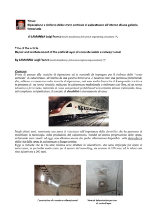
  • 1. Titolo: Riparazione e rinforzo dello strato corticale di calcestruzzo all’interno di una galleria ferroviaria di LAMANNA Luigi Franco (multi-disciplinary, full-service engineering consultant) (* ) Title of the article: Repair and reinforcement of the cortical layer of concrete inside a railway tunnel by LAMANNA Luigi Franco (multi-disciplinary, full-service engineering consultant) (*) Premessa Prima di passare alle tecniche di riparazione ed ai materiali da impiegare per il rinforzo dello “strato corticale” di calcestruzzo, all’interno di una galleria ferroviaria, è doveroso fare una premessa premettendo che, sebbene si conoscono molte tecniche di riparazione, essi sono molto diversi tra di loro quando ci si trova in presenza di un tunnel stradale, realizzato in calcestruzzo tradizionale o rinforzato con fibre, ed un tunnel idraulico o ferroviario, realizzato in conci autoportanti prefabbricati o in cemento armato tradizionale, dove, nel complesso, nel particolare, il concetto di durabilità è enormemente diverso. Negli ultimi anni, nonostante una presa di coscienza sull’importanza della durabilità che ha permesso di modificare la tecnologia, nella produzione del calcestruzzo, nonché un’attenta progettazione delle opere, utilizzando nuovi limiti, ad oggi, non abbiamo ancora che poche informazioni disponibili sulla durevolezza della vita delle opere in calcestruzzo a lungo termine. Oggi si richiede che la vita utile minima delle strutture in calcestruzzo, che sono impiegate per opere in sotterraneo, in particolar modo come per il settore del tunnelling, sia minimo di 100 anni, ed in taluni casi sino ad arrivare a 200 anni. Construction of a modern railway tunnel View of delamination portion of cortical layer
  • 2. In questo caso è sufficiente adottare i criteri di durabilità enunciati nelle norme europee e quelle americane proposte dall’ ACI Comittee 201 (Guide of Durable Concrete in ACI Manual 1994). Il calcestruzzo essendo un materiale rigido e quindi soggetto a fessurazioni quando insorgono, oltre alle sollecitazioni di trazione, le variazioni igro-termiche. Ciò comporta la penetrazione degli agenti aggressivi attraverso le fessure che si vengono a creare ed il successivo degrado del calcestruzzo. Gli agenti aggressivi più conosciuti, che determinano il degrado del calcestruzzo sono, in particolare: a) – l’aggressivita’ dell’ambiente: atmosfera (marina, industriale), acque (meteoriche, corsi d’acqua), clima e microambiente con cui la struttura convive, come: - vibrazioni; - azione disgregazione meccanica, provocata dal gelo e disgelo; - aggressione chimica, dovuta ai solfati, cloruri, sali di magnesio, olii, ecc. b) – la durabilita’ intrinseca del calcestruzzo dovuto a deficienze tecnologiche, come: - errato proporzionamento nella scelta dei materiali costituenti il calcestruzzo (cemento, additivi, acqua); - macro e micro porosità diffusa o concentrata (un calcestrruzzo compatto, omogeneo ed impermeabile offrira’ una maggiore resistenza alla penetrazione di acqua e gas rispetto ad un calcestruzzo di mediocre qualita’, disomogeneo, fessurato e poroso). Deterioration of cortical layer of concrete c) – gli errori o carenze risalenti alla costruzione. Errori di esecuzione, come: - la non corretta combinazione dei materiali calcestruzzo-acciaio e la non sufficiente attenzione al quadro fessurativo del calcestruzzo causato ed accelerato da fenomeni meccanici, come urti e vibrazioni; - esasperata tendenza allo sfruttamento completo della struttura per ragioni architettoniche ed economiche. Causes of corrosion due to stray or leakage currents.
  • 3. Mentre ci sono anche, con una notevole influenza, le correnti vaganti, presenti nei tunnel di metropolitane e ferroviari, specialmente al di sotto di zone urbane o di stazioni ferroviarie che, oltre all’ incendio hanno un’azione diretta sul calcestruzzo, argomento poco dibattuto. Le correnti vaganti I tunnel ferroviari sono molto soggetti alla presenza di correnti vaganti i quali influiscono notevolmente la corrosione delle armature presenti all’interno dei manufatti in calcestruzzo. Vale la pena ricordare che per correnti vaganti (continue) si intendono quelle disperse da circuiti elettrici e che, circolando nel terreno, entrano negli elementi metallici estranei al circuito ma in contatto con il terreno, corrodendoli nelle zone di uscita del flusso. Le correnti vaganti non sono controllabili perché quando vengono scaricate a terra dai binari ferroviari sovrastanti i tunnel assumono differenti direzioni. Da indagini effettuate risulta che l’impiego di un calcestruzzo fibrorinforzato riduce notevolmente la velocità di corrosione delle armature all’interno dei manufatti in calcestruzzo (in particolare dei conci) senza provocare dissoluzione del metallo. L’incendio Una breve descrizione sull’azione di degradazione che il calcestruzzo subisce a causa di un incendio dipende molto dalla temperatura che esso ha raggiunto nei suoi vari punti e dal tempo durante il quale queste temperature hanno avuto modo di far sentire la loro azione. Va ricordato che è fondamentale per poter stabilire lo stato di degradazione di una struttura in calcestruzzo la conoscenza delle temperature raggiunte a diverse profondità nelle varie sezioni dell’elemento strutturale di una galleria. Di questo argomento così importante parleremo, in modo più dettagliato, in un’altra occasione. Materiali per il ripristino Il successo del ripristino di strutture in calcestruzzo armato degradate dipende fondamentalmente dalla solidarizzazione (adesione) fra il nuovo materiale di ripristino ed il vecchio supporto in calcestruzzo. A mio avviso, allo stato attuale della conoscenza tecnologica, anche per la velocità di esecuzione, senza bloccare il traffico ferroviario, esistono tre categorie di materiali che presentano queste proprietà, e sono: d) - le malte resinose (malte e/o calcestruzzi polimerici); e) - le malte/calcestruzzi cementizi a ritiro compensato (reoplastiche e/o fibro-rinforzate e non) ; f) - miscela di calcestruzzo ad elevatissime prestazioni Ultra-High-Performance-Concrete (UHPC). Voglio ricordare che le malte resinose (formulati polimerici) presentano lo svantaggio che con il crescere della temperatura, superiore ai 100° C, subiscono dei cambiamenti di natura chimico-fisica che portano al decadimento delle loro caratteristiche meccaniche. Typical example of repair of cortical layer of deteriorated concrete
  • 4. d.1) - Malte resinose Le malte resinose e/o i calcestruzzi resinosi sono masse di consistenza simile alle malte con leganti minerali conosciute ed impiegate nell’edilizia, ma con legante a base resinosa. La consistenza di queste masse, da fluida e scorrevole sino ad asciutta, dipende dalla loro formulazione. Le caratteristiche tipiche di questi prodotti, che vengono generalmente chiamate malte sintetiche o calcestruzzi polimerici, sono le straordinarie resistenze meccaniche e chimiche, le notevoli caratteristiche di adesione ai comuni materiali da costruzione e la variabilità dei tempi di indurimento, da pochi minuti sino a massimo un’ora. Comunque senza addentrarci nel complesso mondo della CHIMICA delle resine, parleremo soltanto dei formulati resinosi di quelli organici macromolecolari, derivanti dalla polimerizzazione di monomeri, in particolare delle resine termoindurenti (molecole tridimensionali) la cui formazione di macromolecole si ottiene per poliaddizione. Analogamente a come si usa nell’edilizia , si chiamano malte resinose quelle con cariche inerti con diametro max. inferiore ai 4 mm e calcestruzzi resinosi quelli con cariche inerti con diametro max. superiore ai 4 mm. In particolare, le caratteristiche dei formulati per poliaddizione che suggerisco di utilizzare, sono: - Un legante precaricato, per conglomerati di resina impiegando inerti di quarzo di granulometria da 0,05 sino a 0,1 mm e deve presentare le seguenti caratteristiche meccaniche e deformabilità: • resistenza alla compressione 1.050 kg/cm2 ; • resistenza alla flessione 650 kg/cm2 ; • resistenza alla trazione 450 kg/cm2 ; • modulo elastico 70.000 kg/cm2 ; • allungamento a rottura 0,8 %; - un conglomerato di resina, realizzato in betoniera, come il precedente, ma caricato con inerti aventi una precisa curva granulometrica per realizzare conglomerati resinosi con particolari caratteristiche meccaniche e con un ritorno elastico, sotto sforzo di deformazione pari al 95% e deve presentare le seguenti caratteristiche meccaniche e deformabilità: • resistenza alla compressione 1.200 kg/cm2 ; • resistenza alla flessione 350 kg/cm2 ; • resistenza alla trazione 400 kg/cm2 ; • modulo elastico 250.000 kg/cm2 ; Tra gli inerti più usate per la riparazione corticale di calcestruzzi ammalorati è il quarzo, in una vasta gamma di granulometria. La distribuzione granulometrica delle cariche influenza le caratteristiche meccaniche allo stesso modo delle malte cementizie. Valori ottimali si ottengono con una curva granulometrica (la curva di Fuller) che permette di avere il minimo di spazi vuoti. Quindi le particelle medie e fini hanno lo stesso scopo di riempire le cavità grandi e piccole. Esempio tipico di descrizione delle modalità di intervento e di riparazione corticale di strutture in cemento armato con malte o calcestruzzi resinose: d.1.1) - Battitura e saggio su tutte le superfici in calcestruzzo mediante attrezzi manuali per picchiettatura. d.1.2) - Demolizione di ogni parte di calcestruzzo (placche) in fase di distacco o non dotata di sufficiente resistenza o coerenza, mediante idro-demolizione eseguita con lance e pompe a 2.000 Bar o mediante
  • 5. attrezzi manuali e/o con l’aiuto di un piccolo martello a funzionamento elettrico o pneumatico, fino alla profondità dello spessore del copriferro. d.1.2.a) - qualora la rimozione di placche di calcestruzzo ammalorato interessi spessori superiori alla profondità del copriferro, dovranno intervenire poteri decisionali al fine di provvedere ai necessari controlli e alle eventuali istruzioni che tale situazione comporta. d.1.3) - Test-chimico per valutare la profondità di carbonatazione mediante spennellatura sulle parti interessate (nella zona dei ferri di armatura messi a nudo) mediante un reagente chimico del tipo fenolftaleina (raccomandazioni RILEM CPC-18-1983). Con tale metodo, finché le parti “carbonate” non cambiano colore occorre continuare a demolire la massa incoerente fino ad arrivare alle parti di calcestruzzo non carbonato rese visibili da una colorazione tra il violetto ed il rosso. d.1.4) - Scarifica meccanica dell’intera superficie corticale del calcestruzzo non ammalorato di almeno 1 cm., mediante scalpelli montati su apparecchiature azionate elettricamente e/o pneumaticamente fino a mettere a nudo il sottofondo sano e compatto e renderlo sufficientemente scabro, per permettere l’aggancio alla successiva regolarizzazione in malta pronta del tipo bicomponente adesiva, premiscelata, costituita da inerti selezionati di fine granulometria, leganti idraulici modificati ed opportuni additivi (Componente “A”) amalgamati con polimeri acrilici in emulsione (Componente “B”). d.1.5) - Le armature in avanzato stato di degrado dovranno essere scoperte operando una rimozione completa del calcestruzzo all’intorno del ferro. d.1.6) - Dovranno essere rimosse anche quelle tracce di precedenti interventi di riparazione o di riporto non più perfettamente aderenti. Tali operazioni dovranno essere eseguite con mezzi manuali o comunque tali da non danneggiare, con eccessive vibrazioni, lo strato di calcestruzzo non ammalorato, già sottoposto a sollecitazioni dinamiche indotte dal traffico ferroviario. d.1.7) - Accurata pulizia a mezzo di spazzolatura o meglio sabbiatura di tutte le superfici interessate dai successivi trattamenti, con una completa rimozione di sostanze o depositi estranei come ruggine, oli, grassi, pellicole superficiali sfarinanti. Si ottiene così anche una adeguata rugosità delle superfici, utile per una migliore aderenza dei materiali di riporto. d.1.8) - I ferri dovranno essere ripuliti asportando completamente la ruggine secondo SSPC-SP10-63T al grado Sa 2 ½ e ricoperti, a breve distanza, con successivi trattamenti. d.1.9) - I ferri di armatura ripuliti dovranno essere trattati mediante l’applicazione a pennello in due mani, a distanza di circa 2 ore l'una dall'altra, di una malta cementizia pennellabile bicomponente a base di leganti idraulici, polveri silicee, inibitori di corrosione e dispersione di polimeri acrilici (consumo 3 kg. per m² - 2,6 mm. di spessore). d.1.10) - Ove si rendesse necessario si può primerizzare tutta la superficie in calcestruzzo pulita mediante l’applicazione di un “primer” in resina sintetica, in ragione di 300-500 gr. per m², per aumentare il potere di aggrappo superficiale tra il vecchio conglomerato cementizio e il successivo materiale di riporto. Il “primer” deve essere steso su un supporto, privo di incrostazioni e parti friabili, con pennello o sistema airless, perché deve penetrare, anche per capillarità, nei pori del conglomerato cementizio e aderirvi stabilmente dopo l’indurimento, in modo da costituire uno strato superficiale sufficientemente compatto per accogliere il successivo materiale di riporto. d.1.11) - I riporti in spessore per la ricostruzione del copriferro e di parti mancanti dovranno essere realizzati: d.1.12) - mediante applicazione di una malta pronta di resina sintetica del tipo bicomponente adesiva, premiscelata, costituita da inerti minerali (0,1 - 3 mm.) in curva granulometrica nel rapporto legante : quarzo = 1 : 8/13, selezionati di fine granulometria, leganti idraulici modificati ed opportuni additivi (Componente “A”) amalgamati con polimeri in emulsione (Componente “B”) esente da solventi. Questo impasto, senza aggiunta di acqua, dovrà formare una miscela cremosa tixotropica, con basso modulo elastico, da applicare con uno spessore maggiore di 5 mm (resa circa 1.800 kg. per m³. di Componente “A” + Componente “B”).
  • 6. Composition of fillers of quartz aggregates for the study of the Fuller Grunolemtric Curve L'applicazione deve essere eseguita a spatola, con temperatura compresa tra i +5° C e i +35° C, su sottofondo bagnato a rifiuto e successivamente finita con frattazzino di spugna. La malta pronta in resina sintetica ha un elevato potere adesivo al ferro e al calcestruzzo ed un tempo di indurimento abbastanza rapido (da qualche minuto sino ad un’ora max.). Le superfici riparate e l'intera struttura potranno essere, se necessario, protette dal processo di carbonizzazione mediante verniciatura protettiva. d.1.13) - Eventuale posa in opera di rete metallica elettrosaldata, sulle superfici da risanare, e deve essere applicata con il seguente criterio : d.1.13a) - per spessori da risanare minori o uguali a cm. 2 : non è necessario l’impiego di rete metallica elettrosaldata ; d.1.13b) - per spessori da risanare fino a 4 cm. : occorre applicare una rete metallica elettrosaldata con diametro del filo 3 mm., maglia 50x50 mm ; d.1.13c) - per spessori da risanare fino a 6 cm. : occorre applicare una rete metallica elettrosaldata con diametro del filo 4 mm., maglia 50x50 mm. Resin mortar samples for mechanical strength tests Mi preme ricordare che, nel caso di impiego di formulati resinosi, per riparazioni di fessurazioni occorre impiegare formulati con un modulo elastico non superiore a 30.000 kg/cm2 onde evitare, quello che noi addetti ai lavori chiamiamo, effetto cuneo; mentre nel caso di fessurazioni attive è importante che i formulati abbiano un comportamento elastico con moduli inferiori a 10.000 kg/cm2 .
  • 7. e.1) - Malte /calcestruzzi cementizi a ritiro compensato (reoplastiche e/o fibro-rinforzate e non) Trattasi di una malta cementizia, pronta all’uso, con la sola aggiunta di acqua, utilizzata per realizzare placcature a basso spessore sino a 3 - 4 cm, per strutture massicce e soggette prevalentemente a compressione (circa 1.950 kg/m3 ). Oggi tutte le malte a ritiro compensato sono caratterizzate dal fatto che, oltre ai normali componenti, essi contengono anche un agente espansivo in polvere e un certo quantitativo di fibre disperse nell’impasto. In generale, le principali caratteristiche di questi calcestruzzi rispetto a quelli normali sono: una più alta resistenza a flessione, una maggiore duttilità, una maggiore tenacità ed una maggiore resistenza a trazione ed una elevata resistenza agli urti. La loro particolare caratteristica è quella di bilanciare le sollecitazione di trazione differite prodotte dal ritiro igrometrico impedito, attraverso una precompressione chimica del calcestruzzo ottenuta mediante l’introduzione dell’ agente espansivo. Tale componente infatti, è in grado di produrre un’espansione iniziale del calcestruzzo che, se adeguatamente contrastata dalla presenza di vincoli di varia natura, viene trasformata in una sollecitazione di segno opposto a quella indotta dal ritiro igrometrico. Solitamente tale vincolo è dato da una rete elettrosaldata (per compensare le espansioni in fase plastica secondo UNI 8996). La malta può essere anche impiegata con pompe a spruzzo (tipo intonacatrici) o con pompe per iniezioni. La malta ha un elevato potere adesivo al ferro e al calcestruzzo ed un tempo di indurimento abbastanza rapido. Per contro, i calcestruzzi di “malta a ritiro compensato fibrorinforzati” presentano maggiori difficoltà di messa in opera per la riparazione corticale per la presenza delle fibre che riducono sensibilmente la lavorabilità dell’impasto e per la tendenza delle fibre stesse ad intrecciarsi formando delle “palle”. Per quanto esistano molti tipi di fibre (in metallo, vetro, plastica, ecc.) – vedi di seguito alcune successive considerazioni - quelle in acciaio sono quelle che danno le migliori prestazioni ma, purtroppo necessitano di una prolungata maturazione umida. Questa è una ragione che limitano l’impiego di questa tipologia di calcestruzzo. Mechanical resistance test of resinous formulations In pratica nel caso in cui l’idratazione dell’ agente espansivo fosse troppo rapida, rispetto a quella del cemento, la coazione indotta nel calcestruzzo sarebbe assai ridotta in quanto gran parte dell’aumento del volume avverrebbe in un momento in cui il calcestruzzo si trova ancora allo stato plastico. Al contrario, se la cinetica di idratazione dell’ agente espansivo fosse molto lenta, come avviene usando un’altra tipologia di espansivi a base di solfo di alluminati di calcio (anziché ossido di calcio o ossido misto di calcio e magnesio), l’efficacia del processo espansivo sarebbe vincolata all’applicazione di una prolungata stagionatura umida del calcestruzzo.
  • 8. e.1.1) - Alcune raccomandazioni per l’esecuzione del ripristino nell’ applicazione della “malta /calcestruzzi cementizi a ritiro compensato” Le raccomandazioni ed i suggerimenti che seguono sono basati sull’ esperienza del sottoscritto consolidata nell’ applicazione della malta/calcestruzzi cementizi a ritiro compensato reoplastica. e.1.1.1) - nel caso di riporti di spessore superiori ai 2 cm occorre applicare una rete elettrosaldata fissata mediante chiodi al sottofondo. Il sottofondo deve essere irruvidito usando una bocciardatrice sino al calcestruzzo sano creando delle asperità di circa 0,5 cm che assicurino il contrasto all’espansione della malta. e.1.1.2) - l’impiego di fibre d’acciaio nel calcestruzzo proiettato è indicato quando questi servono per contribuire ad aumentare la duttilità del conglomerato cementizio. In questo caso occorre eliminare la posa della rete elettrosaldata. e.1.1.3) - l’impiego delle fibre sintetiche in polipropilene si utilizzano per ottenere, allo stato fresco, una maggiore tixotropicità e un controllo delle fessure durante la fase plastica e quindi una maggiore impermeabilità. Photos of typical fibers for mortar and concrete reinforcement: a) Steel, b) PVA - Polyvinyl alcohol and c) PPHT - High tenacity polypropylene e.1.2) - Caratteristiche dell’impasto indurito e.1.2.1) – buona adesione al calcestruzzo vecchio; e.1.2.2) - resistenza meccanica a compressione: circa 300 kg al cm² a 1 giorno e circa 900 kg al cm² a 28 giorni; e.1.2.3) - resistenza meccanica a trazione per flessione: circa 60 kg al cm² a 1 giorno e oltre 120 kg al cm² a 28 giorni; e.1.2.4) - pull-out: a 3 giorni 45 kg al cm² per barra di acciaio liscia e 200 kg al cm² per barra d’acciaio ad aderenza migliorata; i corrispondenti valori a 28 giorni diventano: 80 kg al cm² ed oltre 330 kg al cm²; e.1.2.5) - espansione libera: 0,3 % tra il tempo d’inizio indurimento (7 ore) e 24 ore; e.1.2.6) - resistenza ai cicli di gelo e disgelo: dopo 300 cicli termici tra – 20° c e + 5° C il modulo elastico dinamico è diminuito meno del 5 % (ASTM-C-233-73); e.1.2.7) - modulo elastico dinamico: 350.000 kg al cm² a 7 giorni e 400.000 kg al cm² a 28 giorni; e.1.2.8) - modulo elastico statico con carichi pari ad un terzo del carico di rottura: 280.000 kg al cm² a 7 giorni e 320.000 kg al cm² a 28 giorni. f.1) – Miscela di calcestruzzo Ultra-High-Performance-Concrete (UHPC) A seguire mi permetto di illustrare un vecchio studio, di notevole attualità ancora oggi, redatto da Stefano Cangiano e Sara Sgobba, della Direzione Ricerca e Sviluppo i. lab, della CTG SPA, Italcementi Group di Bergamo (Italia) i quali sottolineano come negli anni recenti, è stata sviluppata una nuova tecnica nel campo della ricerca per il rinforzo, ripristino ed adeguamento sismico degli elementi RC . Questa soluzione si basa sull'applicazione di un rivestimento sottile in calcestruzzo ad elevatissime prestazioni fibro- rinforzato (UHPFRC) in virtù di una microstruttura cementizia estremamente compatta, ottenuta mediante opportuna scelta dei prodotti costituenti la miscela.
  • 9. Questo tipo di materiali, per loro natura sono molto fragili, però possiedono una elevata caratteristica di tenacità e duttilità dovuta ad una efficace interazione con il fibro-rinforzo. Applicazioni di riabilitazione e rinforzo del calcestruzzo possono essere realizzate con spessori molto ridotti di UHPFRC (circa 30-40 mm) rispetto alle tecniche tradizionali basate sull’utilizzo di calcestruzzi ordinari. Esiste un’ampia letteratura che illustra una grande efficacia di confinamento, miglioramento della tenacità e rafforzamento di elementi strutturali verticali sotto carico assiale, con il vantaggio inoltre di non apportare variazioni significative nelle dimensioni trasversali delle sezioni strutturali. Tra gli altri vantaggi vi è inoltre un incremento di durabilità dovuta alla maggiore compattezza del materiale e l’ottima finitura superficiale legata alle proprietà auto-compattanti, per cui il rivestimento in UHPFRC non necessita successivamente di uno strato di intonaco superficiale. Prove sperimentali hanno dimostrato che ci sono diversi vantaggi tecnici nell'utilizzo di materiali UHPFRC al posto dei materiali tradizionali nel campo dell'adeguamento e della riabilitazione/rinforzo in quanto i materiali cementizi hanno il vantaggio di non soffrire di successivi fenomeni di delaminazione e debonding sotto carichi ciclici e di non presentare reazione al fuoco. Ciò premesso, sul possibile utilizzo delle miscele UHPFRC nella riabilitazione strutturale, poco si conosce sul comportamento micro-meccanico e sulle relative prestazioni in scala macroscopica dell’interfaccia tra vecchio e nuovo calcestruzzo impiegando miscele UHPFRC. f.1.1) – Una breve nota conclusiva sull’impiego delle miscele di calcestruzzo Ultra-High-Performance- Concrete (UHPC) Mi permetto di concludere con una breve nota conclusiva, come già ho avuto occasioni di illustrare un mio personale parere sull’argomento, a riguardo i prodotti e le tecnologie che vengono oggi impiegati, in modo confusionale, per il ripristino ed il rinforzo strutturale di un calcestruzzo tradizionale, utilizzando erroneamente dei calcestruzzi ad elevatissima resistenza, denominati “UHPC”. Questi, gli “UHPC”, non devono essere confusi, come spesso avviene nella realtà, con i calcestruzzi ad elevatissima duttilità, denominati “SHCC” (Strain Hardening Cementitious Composites) o cementi fibrorinforzati, ma sono dei derivati di quest’ultimi come lo sono anche: - HPC (High Performance Concrete), - HSC (High Strength Concrete), - RPC (Reactive Powder Concrete), - DSP (Densified with Small Particles), - FRC (Fiber Reinforced Concrete), - HPFRC (High Performance Fiber Reinforced Concrete), - UHPFRC (Ultra High Performance Fiber Reinforced Concrete), - ECC (Engineered Cementitious Composites), - SCC (Self Compacting Concrete). - Gli “SHCC”, presentano delle grandissime capacità di deformarsi in una zona ben definita (localizzabile) senza fratturarsi in modo incontrollato. Ricordo che i calcestruzzi, denominati “Ultra High Performance Concrete” o brevemente “UHPC”, vengono annoverati come “calcestruzzi ad elevatissime prestazioni” o commercialmente come materiale “GREEN” perché nella formulazione della miscela non presenta resine o componenti plastici. Mi permetto di fare presente, a mio avviso, che questi materiali cementizi, oggi vengono erroneamente indicati, per “migliorare” i calcestruzzi tradizionali in termini di sicurezza strutturale, impiegandoli per ripristini e rinforzi strutturali. Mentre condivido il loro impiego come intonaci ed in modo particolare come elementi prefabbricati in termini di “durabilita” perché, per la loro eccezionale reologia “SCC”, consentono di realizzare dei getti, impiegando delle casseformi, degli spessori molto limitatati.
  • 10. Secondo quanto sopra ho affermato alla voce f.1) , faccio presente che, gli “UHPC” presentano numerosi e importanti caratteristiche, come: • una assoluta impermeabilità. Infatti, l’ impiego di aggiunte minerali (p.es. fumo di silice) che, allocandosi nei vuoti interstiziali lasciati dai granuli di cemento, determinano un sistema meno poroso, più densificato e quindi meccanicamente più resistente oltre che impermeabile agli agenti aggressivi; • una elevata durabilità (dalle 2 alle 3 volte rispetto al cemento tradizionale) e stabilità; • una vasta gamma di colori personalizzabili; • una enorme resistenza a cicli di gelo/disgelo; e notevoli caratteristiche tecniche, come: • una resistenza alla compressione ≥ 140 MPa; • una resistenza alla flessione (matrice) ≥ 18 MPa; • una resistenza alla flessione (rinforzato) ≥ 25 MPa; • una energia di frattura 55 kN/m; • il suo impiego in spessore unitario ≥ 2 mm; • e dopo solo 4 anni una carbonatazione pari a 1.5 mm. • un ridotto rapporto a/c (Acqua/CEmento) per l’impiego di additivi superfluidificanti; • l’impiego di aggregati di frantumazione di alta qualità (basalto, granito, quarzite, ecc.) capaci di assicurare un’elevata resistenza meccanica ed un’ottima adesione all’interfaccia tra aggregato e matrice cementizia; • l’aggiunta di fibre che conferiscono al materiale un comportamento duttile (es. Calcestruzzo “Fiber Reinforced Concrete” o “SHCC” (Strain Hardening Cementitious Composites) denominati cementi fibrorinforzati [si può fare riferimento al Documento Tecnico CNR-DT 204 (2006) ]. Mi dispiace scrivere quanto segue ma, tali materiali, gli “UHPC”, purtroppo presentano alcune “criticità”, in particolare riguardo al “ritiro igrometrico”, il quale ritiro compromette l’ “adesione” al vecchio supporto in calcestruzzo tradizionale, oggetto di riparazione (dello strato corticale). Purtroppo, questo fenomeno di distacco, è normale che si verifica dopo la riparazione dello strato corticale con miscele di “UHPC”, con il successivo passaggio di un treno entro le successive 2 ore. Fenomeno che viene riscontrato nelle zone di riparazione e di rinforzo di porzione di elementi strutturali, durante il ripristino di vecchie gallerie ferroviarie. Dalle immediate verifiche, ho sempre constatato che, la causa di distacco, è sempre dovuto al ritiro igrometrico ed alla mancanza di adesione. Mentre, il fenomeno di distacco, non si è verificato in quelle zone, dove è stata fatta la riparazione dello strato corticale con l’impiego delle malte polimeriche (resinose). Chiedo scusa hai colleghi che non condividono quanto brevemente ho voluto illustrare ma, queste mie affermazioni, sono i risultati di una attenta attività di numerose applicazioni, in fase sperimentale, fatte in diversi cantieri sul territorio nazionale dovute ad esigenze di rinforzo strutturale ed anche di adeguamento sismico. g) - Cosa si intende per calcestruzzo fibro-rinforzato Vorrei ricordare com’è noto a tutti che aggiungendo al calcestruzzo fibre di varia natura, siano esse micro o macro fibre, si ottiene un nuovo “materiale” dalle caratteristiche meccaniche differenti da un convenzionale calcestruzzo. Il conglomerato cementizio diventa fibro-rinforzato quando questi viene additivato con particolari fibre; questi possono essere di: - acciaio;
  • 11. - materiale polimerico; - materiale inorganico (carbonio, vetro). Tale composito viene chiamato Calcestruzzo Fibro-rinforzato (Fiber Reinforced Concrete). Invece quando si parla di un rinforzo costituito da fibre di acciaio questi viene chiamato Steel Fiber Reinforced Concrete. La valutazione delle differenti proprietà tecnologiche del FRC (Fiber Reinforced Concrete) viene effettuata tramite prove unificate e normate alcune delle quali sono quelle tipiche utilizzate per il calcestruzzo ordinario, altre create appositamente per il fibro-rinforzato. Results of the flexural test of mortars reinforced with 1% (V1) and 2% (V2) and 1% (B1) and 2% (B2) basalt glass fibers, compared to that of the mortar unreinforced (TQ). Dall’analisi dell’andamento delle curve carico-spostamento appare evidente che l’aggiunta di fibre comporta il passaggio da una curva tipica di un materiale fragile (curva TQ) a curve caratteristiche di materiali duttili. Le fibre di vetro sembrano, peraltro, avere scarsa influenza sul comportamento elastico del materiale (la pendenza del tratto iniziale delle curve TQ, V1, V2 è sostanzialmente la stessa), con una più decisa influenza sui valori di picco delle resistenze a flessione. Viceversa, la presenza di fibre di basalto non si traduce in sostanziali modifiche sui valori di picco delle resistenze a flessione, mentre sembra influenzare il comportamento del materiale in fase elastica (la curva B2, in particolare, presenta una pendenza del tratto iniziale decisamente inferiore rispetto alle altre). Complessivamente, i migliori risultati sono stati ottenuti con il campione V2, che tra tutti i campioni esaminati ha mostrato sia il valore di picco più elevato (circa 1.100 N) che la più ampia area sottesa dalla curva (valore correlabile alla tenacità del materiale). h) - Le Fibre L’influenza delle fibre sulle proprietà meccaniche di un conglomerato cementizio dipende dalle proprietà del materiale di cui sono costituite, in particolare dalla tenacità e dal modulo elastico a trazione, e da alcuni parametri geometrici quali: • la forma; • la lunghezza; • il diametro equivalente; • il rapporto d’aspetto. Accanto a fibre semplicemente rettilinee esistono fibre ondulate, uncinate, nervate, ad estremità schiacciate, ecc.. La forma indica la geometria della linea d’asse delle fibre e l’eventuale variazione della loro sezione trasversale.
  • 12. Per lunghezza della fibra si intende la distanza tra le due estremità. Essa può differire dalla lunghezza della linea d’asse del lamento nel caso di fibre non rettilinee (ondulate, uncinate, ecc.). Compression stress-deformation behavior of ordinary concrete (green) and one reinforced with metal fibers (yellow) Il diametro equivalente è il diametro del cerchio di area equivalente alla sezione media della fibra. Il rapporto d’aspetto è definito come il rapporto tra la lunghezza della bra e il suo diametro equivalente. A parità di composizione e di dosaggio, l’efficacia delle fibre migliora se aumenta il rapporto d’aspetto e se la forma assume un contorno irregolare che favorisca l’adesione alla matrice cementizia. A seconda del tipo e del dosaggio di fibre impiegate, il comportamento meccanico del calcestruzzo fibro-rinforzato può differire radicalmente da quello di un calcestruzzo ordinario. h.1) - Comportamento a trazione L’aggiunta di fibre non migliora la resistenza meccanica a trazione del calcestruzzo intesa come la sollecitazione in corrispondenza della quale si verifica l’innesco della prima (o unica) fessura nella matrice di un elemento sollecitato a trazione. Non vengono apprezzabilmente modificate le grandezze che caratte- rizzano il comportamento del materiale prima della fessurazione, ossia, il modulo elastico a trazione (Et) e la deformazione in corrispondenza dell’innesco della fessura (εf). L’aggiunta di fibre modifica sensibilmente, invece, il comportamento a trazione della matrice cementizia in fase post-fessurativa. h.2) - Comportamento a flessione La figura che segue si riferisce a prove di flessione effettuate da Roberto TROLI e Francesca SIMONELLI della società Engineering Concrete di TREVISO (Italia), per la caratterizzazione dei calcestruzzi fibro-rinforzati. Sono stati effettuati due tipi di TEST a seconda della norma cui si riferisce la norma belga NBN B15-239, 239 e secondo la norma giapponese JSCE SF4. Altre norme, come la norma italiana UNI 11039, invece, la prova deve essere condotta su travi di analoghe dimensioni ma caratterizzate dalla presenza di un intaglio nella mezzeria del lembo inferiore. In entrambi i casi il comportamento flessionale è sempre definito sulla base di una tensione nominale di trazione valutata ipotizzando un comportamento elastico lineare del provino. Behavior of ordinary concrete (A) and reinforced concrete (B) in the bending test by application of a load P as a function of the deflection
  • 13. Nel calcestruzzo ordinario, al raggiungimento del carico che provoca l’innesco di una fessura, a partire dal lembo maggior- mente teso (Pf), si assiste al collasso repentino dovuto alla rapida propagazione della lesione nell’intero spessore del travetto: in altre parole, la deflessione al momento dell’apparizione della prima fessura (δf) è di poco inferiore (e quasi coincidente) a quella che corrisponde alla completa rottura (δr) come tipicamente avviene in un materiale fragile. h.3) - La tenacità Alla tenacità del calcestruzzo fibro-rinforzato (caratteristica opposta alla fragilità del calcestruzzo ordinario) si deve la capacità di resistere agli urti, qualità particolarmente apprezzata nelle strutture sottoposte a sollecitazioni impulsive e ripetute. h.4) - La resistenza all’urto La resistenza all’urto del calcestruzzo fibro-rinforzato con una prova basata sull’applicazione ripetuta di colpi è determinata con un maglio fino a rottura del materiale. Con un rinforzo adeguato di fibre in acciaio, il provino di calcestruzzo subisce un affossamento nella zona centrale in corrispondenza dell’area sulla quale agisce il maglio, senza tuttavia subire mai alcuna frattura per l’elevatissima resistenza all’urto del calcestruzzo fibro-rinforzato. h.5) - La lavorabilità L’aggiunta di fibre ad un conglomerato cementizio comporta, in genere, una riduzione della lavorabilità dell’impasto rispetto al valore misurato prima dell’aggiunta (Liberato Ferrara and Alberto Meda, “Relationships between bre distribution, workability and the mechanical properties of SFRC applied to precast roof elements” - Materials and Structures, N.39, pp.411–420, 2006). La riduzione della lavorabilità dipende, principalmente, dal dosaggio e dal rapporto d’aspetto delle fibre impiegate. Ai dosaggi di fibre usualmente impiegati nelle applicazioni correnti, comunque, è in genere possibile ottenere un adeguato livello di lavorabilità aggiungendo e dosando opportunamente additivi superfluidificanti e, se necessario, provvedendo ad aumentare la frazione aggregato fine dell’impasto e/o a ridurre il diametro massimo dell’aggregato. h.6) - Il ritiro igrometrico Contrariamente a quanto comunemente ritenuto, l’aggiunta di fibre, di qualsiasi tipo e nei dosaggi usualmente impiegati nelle applicazioni pratiche, non è in grado di ridurre apprezzabilmente il ritiro igrometrico del calcestruzzo e neppure è in grado di ridurre l’apertura delle fessure indotte dal ritiro contrastato da vincoli. Per contro, con l’aggiunta di fibre al calcestruzzo si può ridurre la propagazione delle fessure dovute al ritiro igrometrico grazie all’azione di cucitura esercitata sui lembi delle lesioni che eventualmente si innescano. Questo effetto è ormai largamente utilizzato aggiungendo fibre in acciaio o di tipo polimerico al calcestruzzo in sostituzione delle reti elettrosaldate con funzione di controllo delle fessurazioni da ritiro igrometrico. h.7) - Il ritiro plastico L’aggiunta di fibre di opportune dimensioni e dosaggio può contribuire a prevenire la formazione di cavillature da ritiro plastico nei sistemi cementizi prematuramente esposti all’evaporazione d’acqua. Le fibre che maggiormente risultano efficaci a tale scopo sono le micro-fibre polimeriche caratterizzate da lunghezza compresa tra 3 e 20 mm e diametro dell’ordine di 0,05 ÷ 0,1 mm. i) - Cosa si intende per riparazione o rinforzo strutturale di un’opera in conglomerato cementizio Per riparazione o rinforzo strutturale di un’opera in conglomerato cementizio si intende quell’intervento necessario per ridare l’originaria funzionalità e continuità ad una struttura, che si è degradata sotto l’azione di agenti atmosferici, chimici, meccanici, sismici o a causa di un’errata esecuzione.
  • 14. In particolare, occorre distinguere, tre tipi di interventi: i.1) - Riparazione dello strato corticale di strutture in cemento armato per spessori sino alla profondità del copriferro UNI-EN-1992-1-1 (armatura metallica esistente) , con ripristino della sezione originaria di conglomerato resistente. i.2) – Riparazione dello strato corticale di strutture in cemento armato per spessori superiori alla profondità del copriferro UNI-EN-1992-1-1 (armatura metallica esistente) con ripristino della sezione originaria di conglomerato resistente. i.3) – Riparazione dello strato corticale di strutture in cemento armato per spessori superiori alla profondità del copriferro UNI-EN-1992-1-1 (integrazione dell’armatura metallica esistente mancante), con aumento della sezione originaria di conglomerato resistente. Quest’ultimo punto non è oggetto della presente relazione tecnica – riparazione strato corticale - perchè l’ aumento della sezione di conglomerato resistente deve essere realizzata mediante getto entro cassero allo scopo di ripristinare strutture come pilastri e travi creando le originarie caratteristiche strutturali del progetto mediante un nuovo getto strutturalmente collaborante con l’esistente, entro casseri in lamiera e quando gli spessori lo consentono. L’armatura mancante o in avanzato stato di corrosione, deve essere integrata tramite giunzione, mediante saldatura del tipo elettrico-manuale con elettrodo, utilizzando nuovi spezzoni di ferro del tipo acciaioso. Come potete notare nello descrivere le varie modalità di intervento di riparazioni di strutture in cemento armato, sempre con ripristino della sezione originaria o con aumento della sezione di conglomerato resistente, oltre allo stato corticale esistono altri tipi riparazioni strutturali: lesioni passanti, crepe, giunti rigidi, sempre di elementi portanti in cemento armato il cui ripristino può essere effettuato mediante iniezioni a bassa pressione di formulati di resine sintetiche. Come già detto e scritto in diverse occasioni, ognuno di noi cerca di comunicare con la propria esperienza, a far sviluppare e dare una informazione adeguata alle nuove esigenze che il mercato globale richiede, in particolare su come difendere le nostre strutture infrastrutturali, ricordando che è sempre importante gestire lo sviluppo tecnologico solo e attraverso lo studio continuo della tecnologia dei materiali. Conclusioni In questa breve nota ho solo cercato di descrivere mettendo in evidenza le varie modalità di intervento di riparazioni dello strato corticale in calcestruzzo di una galleria ferroviaria, con struttura in cemento armato, sottolineando, in modo evidente, l’uso dei prodotti a matrice resinosa, oltre per le loro caratteristiche capaci di sopportare sforzi decisamente maggiori avendo per di più un ritorno elastico istantaneo e quasi completo, anche per il loro rapido indurimento. Comunque, il successo del ripristino dipende fondamentalmente dalla solidarizzazione fra il nuovo materiale che si impiega per il ripristino ed il vecchio supporto in calcestruzzo. In altre parole, l’ adesione fra questi due materiali, non deve essere inferiore alla resistenza a trazione, del calcestruzzo da ripristinare. Allo stato attuale della tecnologia conosciuta i prodotti a base di formulati resinosi sono quelli che garantiscono le proprietà richieste perché presentano una forte azione di primer e di penetrazione nel vecchio supporto, ed infine perché mantengono integre – per oltre 100 anni, nell’evolversi nel tempo, le loro caratteristiche meccaniche. Faccio inoltre presente che il nostro obiettivo deve essere mirato a contribuire ad a fare presente che occorre difendere tutte le nostre strutture infrastrutturali attraverso una manutenzione programmata. A tale riguardo ricordo ancora che la nostra rete ferroviaria è l’arteria vitale del mercato unico europeo, ed occorre poter sempre contribuire, anche con una semplice riparazione dello strato corticale, per assicurare quelle condizioni ottimali e uniformi richiesti dalla sicurezza specialmente di quello del trasporto su ferro. Grazie dell’attenzione.
  • 15. Article in English Premise Before moving on to the repair techniques and materials to be used for the reinforcement of the "cortical layer" of concrete, inside a railway tunnel, it is necessary to make a premise premising that, although many repair techniques are known, they are very different from each other when you are in the presence of a road tunnel, made of traditional or fiber-reinforced concrete, and a hydraulic or railway tunnel, made of prefabricated self-supporting ashlars or traditional reinforced concrete, where, overall, in particular, the concept of durability is enormously different. In recent years, despite an awareness of the importance of durability that has made it possible to change the technology in the production of concrete, as well as careful design of the works, using new limits, to date, we still have little information available on long-term durability of concrete works. Today it is required that the minimum useful life of concrete structures, which are used for underground works, especially as for the tunneling sector, is a minimum of 100 years, and in some cases up to 200 years. Construction of a modern railway tunnel View of delamination portion of cortical layer In this case, it is sufficient to adopt the durability criteria set out in the European and American standards proposed by the ACI Committee 201 (Guide of Durable Concrete in ACI Manual 1994). Concrete being a rigid material and therefore subject to cracks when, in addition to tensile stresses, hygro- thermal variations arise. This involves the penetration of aggressive agents through the cracks that are created and the subsequent degradation of the concrete. The most known aggressive agents, which determine the degradation of concrete are, in particular: a) - the aggressiveness of the environment: atmosphere (marine, industrial), waters (meteoric, waterways), climate and microenvironment with which the structure coexists, such as: - vibrations;
  • 16. - mechanical disintegration action, caused by freezing and thawing; - chemical aggression, due to sulphates, chlorides, magnesium salts, oils, etc. b) - the intrinsic durability of concrete due to technological deficiencies, such as: - incorrect proportioning in the choice of the materials making up the concrete (cement, additives, water); - widespread or concentrated macro and micro porosity (a compact, homogeneous and waterproof concrete will offer greater resistance to the penetration of water and gas than a medium quality concrete, uneven, cracked and porous). Deterioration of cortical layer of concrete c) - errors or deficiencies dating back to construction. Execution errors, such as: - the incorrect combination of concrete-steel materials and insufficient attention to the cracking of concrete caused and accelerated by mechanical phenomena, such as shocks and vibrations; - exasperated tendency to fully exploit the structure for architectural and economic reasons. Causes of corrosion due to stray or leakage currents. While there are also, with considerable influence, stray currents, present in the tunnels of subways and railways, especially below urban areas or railway stations which, in addition to the fire, have a direct action on concrete, a topic little debated . Stray currents Railway tunnels are very subject to the presence of stray currents which greatly affect the corrosion of the reinforcements inside the concrete products. It is worth remembering that by stray (direct) currents we mean those dispersed by electrical circuits and that, circulating in the ground, they enter the metal elements extraneous to the circuit but in contact with the ground, corroding them in the areas where the flow is released. Stray currents are not controllable
  • 17. because when they are discharged to the ground from the railway tracks above, the tunnels take different directions. Investigations have shown that the use of fiber-reinforced concrete significantly reduces the rate of corrosion of the reinforcements inside the concrete products (in particular of the ashlars) without causing dissolution of the metal. The fire A brief description of the degradation action that concrete undergoes due to a fire depends very much on the temperature it has reached at its various points and on the time during which these temperatures have had the opportunity to make their action felt. It should be remembered that knowledge of the temperatures reached at different depths in the various sections of the structural element of a tunnel is essential in order to establish the degradation state of a concrete structure. We will talk about this important topic in more detail on another occasion. Materials for restoration Successful restoration of degraded reinforced concrete structures basically depends on the solidarity (adhesion) between the new restoration material and the old concrete support. In my opinion, in the current state of technological knowledge, also for the speed of execution, without blocking rail traffic, there are three categories of materials that have these properties, and they are: d) - resinous mortars (mortars and / or polymer concretes); e) - compensated shrinkage mortars / concretes (rheoplastic and/or fiber-reinforced and non-reinforced); f) - Ultra-High-Performance-Concrete (UHPC) concrete mix. I want to remind you that the resin mortars (polymeric formulations) have the disadvantage that with the increase of the temperature, higher than 100° C, they undergo chemical-physical changes which lead to the decay of their mechanical characteristics. Typical example of repair of cortical layer of deteriorated concrete d.1) - Resinous mortars Resinous mortars and/or resinous concretes are masses of a consistency similar to mortars with known mineral binders and used in construction, but with a resin-based binder. The consistency of these masses, from fluid and flowing to dry, depends on their formulation. The typical characteristics of these products, which are generally called synthetic mortars or polymer concretes, are the extraordinary mechanical and chemical resistance, the remarkable adhesion characteristics to common building materials and the variability of the hardening times, from a few minutes up to a maximum of 1 Now.
  • 18. However, without going into the complex world of resin CHEMISTRY, we will only talk about the resinous formulations of the macromolecular organic ones, deriving from the polymerization of monomers, in particular of the thermosetting resins (three-dimensional molecules) whose formation of macromolecules is obtained by poly-addition. Similarly to how it is used in construction, resinous mortars are called those with inert fillers with a maximum diameter. less than 4 mm and resinous concretes those with inert fillers with max. diameter. greater than 4 mm. In particular, the characteristics of the polyaddition formulations that I suggest to use are: - a preloaded binder, for resin conglomerates using quartz aggregates of granulometry from 0.05 to 0.1 mm and must have the following mechanical characteristics and deformability: • compressive strength 1,050 kg / cm2 ; • flexural strength 650 kg / cm2 ; • tensile strength 450 kg / cm2 ; • elastic modulus 70.000 kg / cm2 ; • elongation at break 0.8 %; - a resin conglomerate, made in a concrete mixer, like the previous one, but loaded with aggregates having a precise granulometric curve to make resinous conglomerates with particular mechanical characteristics and with an elastic return, under deformation effort equal to 95% and must have the following mechanical characteristics and deformability: • compressive strength 1,200 kg / cm2 ; • flexural strength 350 kg / cm2 ; • tensile strength 400 kg / cm2 ; • elastic modulus 250.000 kg / cm2 ; Among the most used aggregates for the cortical repair of deteriorated concretes is quartz, in a wide range of granulometry. The granulometric distribution of fillers influences the mechanical characteristics in the same way as cement mortars. Optimal values are obtained with a particle size curve (the Fuller curve) which allows to have the minimum of empty spaces. So medium and fine particles have the same purpose of filling large and small cavities. Typical example of description of the methods of intervention and cortical repair of reinforced concrete structures with mortars or resinous concretes: d.1.1) - Beating and testing on all concrete surfaces using manual tapping tools. d.1.2) - Demolition of any part of concrete (slabs) in the detachment phase or not endowed with sufficient strength or consistency, by means of hydro-demolition performed with lances and pumps at 2,000 Bar or by manual tools and/or with the help of a small electric or pneumatic hammer, up to the depth of the concrete cover thickness. d.1.2.a) - if the removal of deteriorated concrete plates affects thicknesses greater than the depth of the concrete cover, decision-making powers must intervene in order to provide the necessary checks and any instructions that this situation entails. d.1.3) - Chemical test to evaluate the depth of carbonation by brushing on the interested parts (in the area of the exposed reinforcement rods) by means of a chemical reagent of the phenolphthalein type (recommendations RILEM CPC-18-1983). With this method, as long as the "carbonate" parts do not change color, it is necessary to continue demolishing the inconsistent mass until reaching the parts of non-carbonated concrete made visible by a coloring between violet and red.
  • 19. d.1.4) - Mechanical scarification of the entire cortical surface of the non-deteriorated concrete of at least 1 cm, by means of chisels mounted on electrically and/or pneumatically operated equipment until the healthy and compact substratum is exposed and made sufficiently rough, to allow the coupling to the subsequent regularization in ready-mixed two-component adhesive mortar, premixed, consisting of selected aggregates of fine grain size, modified hydraulic binders and appropriate additives (Component "A") mixed with acrylic polymers in emulsion (Component "B"). d.1.5) - Reinforcements in an advanced state of degradation must be discovered by performing a complete removal of the concrete around the iron. d.1.6) - Those traces of previous repair or carry-over operations which are no longer perfectly adherent must also be removed. These operations must be carried out with manual means or in any case such as not to damage, with excessive vibrations, the layer of undamaged concrete, already subjected to dynamic stresses induced by railway traffic. d.1.7) - Careful cleaning by brushing or better sandblasting of all surfaces affected by subsequent treatments, with complete removal of foreign substances or deposits such as rust, oils, greases, chalking surface films. An adequate roughness of the surfaces is also obtained, which is useful for a better adhesion of the filler materials. d.1.8) - The irons must be cleaned by completely removing the rust according to SSPC-SP10-63T to the Sa 2 ½ grade and covered, at a short distance, with subsequent treatments. d.1.9) - The cleaned reinforcement rods must be treated by applying two-component brushing mortar based on hydraulic binders, silica powders with a brush in two coats, about 2 hours apart. , corrosion and dispersion inhibitors of acrylic polymers (consumption 3 kg. per m² - 2.6 mm. thickness). d.1.10) - If necessary, the entire clean concrete surface can be primed by applying a synthetic resin "primer", in the ratio of 300-500 gr. per m², to increase the surface clinging power between the old cement conglomerate and the subsequent filling material. The "primer" must be spread on a substrate, free of incrustations and crumbly parts, with a brush or airless system, because it must penetrate, also by capillarity, into the pores of the cement conglomerate and adhere to it stably after hardening, so as to form one surface layer compact enough to accommodate the subsequent filler material. d.1.11) - The thick coatings for the reconstruction of the concrete cover and missing parts must be made: d.1.12) - by applying a ready-mixed, ready-mixed two-component adhesive synthetic mortar made up of mineral aggregates (0.1 - 3 mm.) in a grain size curve in the binding ratio: quartz = 1: 8/13, selected fine grain size, modified hydraulic binders and appropriate additives (Component "A") mixed with emulsion polymers (Component "B") free of solvents. This mixture, without adding water, must form a thixotropic creamy mixture, with a low elastic modulus, to be applied with a thickness greater than 5 mm (yield approximately 1,800 kg/m³ of Component "A" + Component "B"). Composition of fillers of quartz aggregates for the study of the Fuller Grunolemtric Curve
  • 20. I would like to remind you that, in the case of the use of resinous formulations, for repairs of cracks it is necessary to use formulations with an elastic modulus not exceeding 30,000 kg / cm2 in order to avoid what we experts call, wedge effect; while in the case of active cracks it is important that the formulations have an elastic behavior with modules less than 10,000 kg / cm2 . e.1) - Mortars / cementitious concrete with compensated shrinkage (rheoplastic and / or fiber-reinforced and non-reinforced) This is a ready-to-use cement mortar, with the only addition of water, used to create low thickness plating up to 3 - 4 cm, for massive structures and mainly subject to compression (about 1,950 kg / m3 ). Today all compensated shrinkage mortars are characterized by the fact that, in addition to the normal components, they also contain an expansive powder agent and a certain amount of fibers dispersed in the mix. In general, the main characteristics of these concretes compared to normal ones are: higher flexural strength, greater ductility, greater toughness and greater tensile strength and high impact resistance. Their particular feature is to balance the deferred tensile stresses produced by the prevented hygrometric shrinkage, through a chemical precompression of the concrete obtained by introducing the expansive agent. In fact, this component is capable of producing an initial expansion of the concrete which, if adequately contrasted by the presence of various constraints, is transformed into a stress of opposite sign to that induced by the hygrometric shrinkage. Usually this constraint is given by an electro-welded mesh (to compensate for expansions in the plastic phase according to UNI 8996). The mortar can also be used with spray pumps (plastering machines) or with injection pumps. The mortar has a high adhesive power to iron and concrete and a fairly rapid hardening time. On the other hand, "fiber-reinforced compensated shrinkage mortar" concretes present greater difficulties in setting up for cortical repair due to the presence of fibers which significantly reduce the workability of the mix and the tendency of the fibers themselves to intertwine forming "balls" ". Although many types of fibers exist (in metal, glass, plastic, etc.) - see below some subsequent considerations - those in steel are the ones that give the best performance but, unfortunately, need a prolonged wet maturation. This is a reason that limits the use of this type of concrete. Mechanical resistance test of resinous formulations
  • 21. In practice, if the hydration of the expansive agent was too rapid, compared to that of the cement, the coercion induced in the concrete would be very small since most of the increase in volume would occur at a time when the concrete is located. still in the plastic state. On the contrary, if the hydration kinetics of the expansive agent were very slow, as occurs using another type of sulfate-based expanses of calcium aluminates (instead of calcium oxide or mixed calcium and magnesium oxide), the effectiveness of the expansion process would be tied to the application of a prolonged wet seasoning of the concrete. e.1.1) - Some recommendations for the restoration of the "compensated shrinkage mortar / concrete" The following recommendations and suggestions are based on the experience of the undersigned consolidated in the application of mortar/concretes with shrinkage compensated shrinkage. e.1.1.1) - in the case of coatings with a thickness greater than 2 cm, an electro-welded mesh fixed with nails to the substrate must be applied. The substrate must be roughened using a bushhammering machine up to the healthy concrete creating roughnesses of about 0.5 cm which ensure the contrast to the expansion of the mortar. e.1.1.2) - the use of steel fibers in the projected concrete is indicated when these are used to help increase the ductility of the cement mix. In this case, the laying of the welded mesh must be eliminated. e.1.1.3) - the use of synthetic polypropylene fibers are used to obtain, in the fresh state, greater thixotropicity and control of the cracks during the plastic phase and therefore greater impermeability. Photos of typical fibers for mortar and concrete reinforcement: a) Steel, b) PVA - Polyvinyl alcohol and c) PPHT - High tenacity polypropylene e.1.2) - Characteristics of the hardened dough e.1.2.1) - good adhesion to old concrete; e.1.2.2) - mechanical compressive strength: approximately 300 kg per cm² after 1 day and approximately 900 kg per cm² after 28 days; e.1.2.3) - mechanical tensile strength for bending: about 60 kg per cm² after 1 day and over 120 kg per cm² after 28 days; e.1.2.4) - pull-out: at 3 days 45 kg per cm² for a smooth steel bar and 200 kg per cm² for an improved adhesion steel bar; the corresponding 28-day values become: 80 kg per cm² and over 330 kg per cm²; e.1.2.5) - free expansion: 0.3% between the hardening start time (7 hours) and 24 hours; e.1.2.6) - resistance to freeze-thaw cycles: after 300 thermal cycles between - 20 ° c and + 5 ° C the dynamic elastic modulus decreased by less than 5% (ASTM-C-233-73); e.1.2.7) - dynamic elastic modulus: 350,000 kg per cm² after 7 days and 400,000 kg per cm² after 28 days; e.1.2.8) - static elastic modulus with loads equal to one third of the breaking load: 280,000 kg per cm² in 7 days and 320,000 kg per cm² in 28 days.
  • 22. f.1) - Ultra-High-Performance-Concrete (UHPC) concrete mix Following I would like to illustrate an old study, still relevant today, written by Stefano Cangiano and Sara Sgobba, of the Research and Development Department i. lab, of CTG SPA, Italcementi Group of Bergamo (Italy) which underline how in recent years, a new technique has been developed in the field of research for the reinforcement, restoration and seismic adaptation of RC elements. This solution is based on the application of a thin concrete coating with very high fiber-reinforced performance (UHPFRC) by virtue of an extremely compact cement microstructure, obtained through a suitable choice of the products making up the mixture. This type of materials, by their nature are very fragile, however they have a high characteristic of toughness and ductility due to an effective interaction with the fiber-reinforcement. Rehabilitation and concrete reinforcement applications can be achieved with very reduced thicknesses of UHPFRC (about 30-40 mm) compared to traditional techniques based on the use of ordinary concrete. There is a large literature that illustrates a great effectiveness of confinement, improvement of toughness and strengthening of vertical structural elements under axial load, with the advantage also of not making significant changes in the transverse dimensions of the structural sections. Among the other advantages there is also an increase in durability due to the greater compactness of the material and the excellent surface finish linked to the self-compacting properties, so the UHPFRC coating does not subsequently need a layer of surface plaster. Experimental tests have shown that there are several technical advantages in the use of UHPFRC materials instead of traditional materials in the field of adaptation and rehabilitation / reinforcement as cementitious materials have the advantage of not suffering from subsequent delamination and debonding phenomena under cyclic loads and not to exhibit a reaction to fire. Having said that, on the possible use of UHPFRC mixtures in structural rehabilitation, little is known about the micro-mechanical behavior and related macroscopic performance of the interface between old and new concrete using UHPFRC mixtures. f.1.1) - A brief final note on the use of Ultra-High-Performance-Concrete (UHPC) concrete mixtures Allow me to conclude with a brief concluding note, as I have already had occasion to illustrate my personal opinion on the subject, regarding the products and technologies that are used today, in a confusing way, for the restoration and structural reinforcement of a traditional concrete, mistakenly using very high strength concretes, called "UHPC". These, the "UHPC", must not be confused, as often happens in reality, with very high ductility concretes, called "SHCC" (Strain Hardening Cementitious Composites) or fiber-reinforced cements, but they are derivatives of the latter as they are also: - HPC (High Performance Concrete), - HSC (High Strength Concrete), - RPC (Reactive Powder Concrete), - DSP (Densified with Small Particles), - FRC (Fiber Reinforced Concrete), - HPFRC (High Performance Fiber Reinforced Concrete), - UHPFRC (Ultra High Performance Fiber Reinforced Concrete), - ECC (Engineered Cementitious Composites), - SCC (Self Compacting Concrete). The "SHCC" have very great ability to deform in a well-defined (localizable) area without fracturing in an uncontrolled way. Remember that concretes, called "Ultra High Performance Concrete" or briefly "UHPC", are counted as "very high performance concretes" or commercially as "GREEN" material because in the formulation of the mixture it does not have resins or plastic components.
  • 23. I take the liberty of pointing out, in my opinion, that these cementitious materials are now erroneously indicated, to "improve" traditional concretes in terms of structural safety, using them for restorations and structural reinforcements. While I share their use as plasters and in particular as prefabricated elements in terms of "durability" because, due to their exceptional "SCC" rheology, they allow you to make castings, using formwork, with very limited thicknesses. According to what I said under item f.1), I would like to point out that the "UHPC" have numerous and important characteristics, such as: • absolute impermeability. In fact, the use of mineral additions (e.g. silica smoke) which, allocating themselves in the interstitial voids left by the cement granules, determine a less porous, more densified and therefore mechanically more resistant system as well as impervious to aggressive agents; • high durability (2 to 3 times compared to traditional cement) and stability; • a wide range of customizable colors; • an enormous resistance to freeze / thaw cycles; and remarkable technical characteristics, such as: • a compressive strength ≥ 140 MPa; • a flexural strength (matrix) ≥ 18 MPa; • a flexural strength (reinforced) ≥ 25 MPa; • a fracture energy 55 kN / m; • its use in unitary thickness ≥ 2 mm; • and after only 4 years a carbonation of 1.5 mm. • a reduced a / c ratio (Water / Cement) for the use of superplasticizing additives; • the use of high quality crushing aggregates (basalt, granite, quartzite, etc.) capable of ensuring high mechanical strength and excellent adhesion to the interface between the aggregate and the cement matrix; • the addition of fibers that give the material a ductile behavior (eg "Fiber Reinforced Concrete" or "SHCC" (Strain Hardening Cementitious Composites) called fiber-reinforced cements [refer to the Technical Document CNR-DT 204 (2006) ]. I am sorry to write the following but, such materials, the "UHPC", unfortunately have some "criticalities", in particular with regard to the "hygrometric shrinkage", which shrinkage compromises the "adhesion" to the old traditional concrete support, which is being repaired (of the cortical layer). Unfortunately, this detachment phenomenon is normal that occurs after the repair of the cortical layer with mixtures of "UHPC", with the subsequent passage of a train within the following 2 hours. Phenomenon that is found in the areas of repair and reinforcement of a portion of structural elements, during the restoration of old railway tunnels. From the immediate checks, I have always found that the cause of detachment is always due to the hygrometric shrinkage and the lack of adhesion. While, the detachment phenomenon did not occur in those areas, where the repair of the cortical layer was made with the use of polymeric (resinous) mortars. I apologize you have colleagues who do not share how briefly I wanted to illustrate but, these statements of mine, are the results of a careful activity of numerous applications, in the experimental phase, made in different construction sites on the national territory due to needs of structural reinforcement and also of adaptation seismic.
  • 24. g) - What is meant by fiber-reinforced concrete I would like to remind you that everyone is aware that by adding various types of fibers to the concrete, be they micro or macro fibers, a new "material" with mechanical characteristics different from a conventional concrete is obtained. The cement conglomerate becomes fiber-reinforced when it is added with particular fibers; these can be of: - steel; - polymeric material; - inorganic material (carbon, glass). This composite is called Fiber Reinforced Concrete. Instead when we speak of a reinforcement consisting of steel fibers, this is called Steel Fiber Reinforced Concrete. The evaluation of the different technological properties of the FRC (Fiber Reinforced Concrete) is carried out through standardized and unified tests, some of which are the typical ones used for ordinary concrete, others created specifically for fiber-reinforced concrete. Results of the flexural test of mortars reinforced with 1% (V1) and 2% (V2) and 1% (B1) and 2% (B2) basalt glass fibers, compared to that of the mortar unreinforced (TQ). From the analysis of the trend of the load-displacement curves, it is evident that the addition of fibers involves the transition from a typical curve of a fragile material (TQ curve) to characteristic curves of ductile materials. Moreover, the glass fibers seem to have little influence on the elastic behavior of the material (the slope of the initial section of the curves TQ, V1, V2 is substantially the same), with a more decisive influence on the peak values of the flexural strengths. Vice versa, the presence of basalt fibers does not translate into substantial changes on the peak values of the flexural strengths, while it seems to influence the behavior of the material in the elastic phase (curve B2, in particular, presents a slope of the initial stretch much lower than to the others). Overall, the best results were obtained with the V2 sample, which among all the samples examined showed both the highest peak value (around 1,100 N) and the largest area subtended by the curve (value correlated to the toughness of the material).
  • 25. h) – Fibers The influence of the fibers on the mechanical properties of a concrete conglomerate depends on the properties of the material they are made of, in particular by the toughness and the elastic modulus of traction, and by some geometric parameters such as: • shape; • the length; • the equivalent diameter; • the aspect ratio. Next to simply rectilinear fibers there are corrugated, hooked, ribbed fibers, with flattened ends, etc. The shape indicates the geometry of the centerline of the fibers and the possible variation of their cross section. By fiber length is meant the distance between the two ends. It may differ from the length of the centerline of the lament in the case of non-rectilinear fibers (wavy, hooked, etc.). Compression stress-deformation behavior of ordinary concrete (green) and one reinforced with metal fibers (yellow) The equivalent diameter is the diameter of the circle with an area equivalent to the average section of the fiber. The aspect ratio is defined as the ratio between the length of the bra and its equivalent diameter. With the same composition and dosage, the effectiveness of the fibers improves if the aspect ratio increases and if the shape assumes an irregular contour that favors adhesion to the cement matrix. Depending on the type and dosage of fibers used, the mechanical behavior of fiber-reinforced concrete can differ radically from that of ordinary concrete. h.1) - Traction behavior The addition of fibers does not improve the mechanical tensile strength of concrete intended as the stress at which the triggering of the first (or only) crack in the matrix of an element stressed by traction occurs. The quantities that characterize the behavior of the material before cracking are not appreciably changed, that is, the elastic modulus of traction (Et) and the deformation at the crack trigger (εf). The addition of fibers significantly changes, however, the tensile behavior of the cement matrix in the post-cracking phase. h.2) - Bending behavior The following figure refers to bending tests carried out by Roberto TROLI and Francesca SIMONELLI of the Engineering Concrete company of TREVISO (Italy), for the characterization of fiber-reinforced concrete. Two types of TEST were carried out according to the standard to which the Belgian standard NBN B15-239, 239 refers and according to the Japanese standard JSCE SF4. Other standards, such as the Italian UNI 11039 standard, on the other hand, the test must be carried out on beams of similar dimensions but characterized by the presence of a notch in the center of the lower edge. In both cases, the bending behavior is always
  • 26. defined on the basis of a nominal tensile stress evaluated assuming a linear elastic behavior of the specimen. Behavior of ordinary concrete (A) and reinforced concrete (B) in the bending test by application of a load P as a function of the deflection In ordinary concrete, upon reaching the load that causes the initiation of a crack, starting from the most stretched flap (Pf), there is a sudden collapse due to the rapid propagation of the lesion in the entire thickness of the joist: in other words , the deflection at the time of the appearance of the first crack (δf) is slightly less (and almost coincident) than that which corresponds to the complete break (δr) as typically occurs in a fragile material. h.3) – Tenacity The toughness of fiber-reinforced concrete (a characteristic opposite to the fragility of ordinary concrete) is due to its ability to withstand impacts, a quality particularly appreciated in structures subjected to impulsive and repeated stresses. h.4) - The impact resistance The impact resistance of fiber-reinforced concrete with a test based on the repeated application of blows is determined with a mallet until the material breaks. With an adequate reinforcement of steel fibers, the concrete specimen undergoes a sinking in the central area in correspondence of the area on which the mallet acts, without however suffering any fracture due to the very high impact resistance of the fiber-reinforced concrete. h.5) – Workability The addition of fibers to a cement conglomerate generally involves a reduction in the workability of the mix compared to the value measured before the addition (Liberato Ferrara and Alberto Meda, "Relationships between bre distribution, workability and the mechanical properties of SFRC applied to precast roof elements "- Materials and Structures, N.39, pp.411–420, 2006). The reduction in workability depends mainly on the dosage and the aspect ratio of the fibers used. However, it is generally possible to obtain an adequate level of workability at the dosages of fibers usually used in current applications by adding and appropriately dosing superplasticizing additives and, if necessary, by increasing the fine aggregate fraction of the mixture and / or reducing the maximum diameter aggregate. h.6) - The hygrometric withdrawal Contrary to what is commonly believed, the addition of fibers, of any type and in the dosages usually used in practical applications, is not able to appreciably reduce the hygrometric shrinkage of the concrete and neither is it able to reduce the opening of the cracks induced by the retreat thwarted by constraints. On the other hand, with the addition of fibers to the concrete it is possible to reduce the propagation of the cracks due to the hygrometric shrinkage thanks to the stitching action exerted on the edges of the lesions that may trigger. This effect is now widely used by adding steel or polymeric fibers to the concrete to replace the welded meshes with the function of controlling the cracks due to hygrometric shrinkage.
  • 27. h.7) - Plastic withdrawal The addition of fibers of suitable size and dosage can help prevent the formation of cracks due to plastic shrinkage in cement systems that are prematurely exposed to water evaporation. The fibers that are most effective for this purpose are polymeric micro-fibers characterized by a length between 3 and 20 mm and a diameter of the order of 0.05 ÷ 0.1 mm. i) - What is meant by repair or structural reinforcement of a concrete conglomerate work By repair or structural reinforcement of a work in cement conglomerate is meant the intervention necessary to restore the original functionality and continuity to a structure, which deteriorated under the action of atmospheric, chemical, mechanical, seismic agents or due to an incorrect execution. In particular, three types of interventions must be distinguished: i.1) - Repair of the cortical layer of reinforced concrete structures for thicknesses up to the depth of the concrete cover UNI-EN-1992-1-1 (existing metal reinforcement), with restoration of the original section of resistant conglomerate. i.2) - Repair of the cortical layer of reinforced concrete structures for thicknesses greater than the depth of the concrete cover UNI-EN-1992-1-1 (existing metal reinforcement) with restoration of the original section of resistant conglomerate. i.3) - Repair of the cortical layer of reinforced concrete structures for thicknesses greater than the depth of the concrete cover UNI-EN-1992-1-1 (integration of the existing metal reinforcement missing), with an increase in the original section of resistant conglomerate. This last point is not the subject of this technical report - cortical layer repair - because the increase in the section of resistant conglomerate must be carried out by casting into formwork in order to restore structures such as pillars and beams creating the original structural characteristics of the project by means of a new casting structurally collaborating with the existing one, in sheet metal formwork and when the thickness allows it. The missing armor or in an advanced state of corrosion, must be integrated by joining, by welding of the electric-manual type with electrode, using new pieces of iron of the steel type. As you can see in describing the various methods of repairing reinforced concrete structures, always with restoration of the original section or with an increase in the section of resistant conglomerate, in addition to the cortical state, there are other types of structural repairs: through injuries, cracks, rigid joints , again of load-bearing elements in reinforced concrete whose restoration can be carried out by low-pressure injections of synthetic resin formulations. As already said and written on several occasions, each of us tries to communicate with his own experience, to develop and give adequate information to the new needs that the global market requires, in particular on how to defend our infrastructure structures, remembering that it is It is always important to manage technological development only and through the continuous study of material technology. Conclusions In this short note I have only tried to describe by highlighting the various methods of repairing the cortical concrete layer of a railway tunnel, with a reinforced concrete structure, clearly emphasizing the use of resinous matrix products, in addition to their characteristics capable of withstanding decidedly greater efforts, furthermore having an instantaneous and almost complete elastic return, also for their rapid hardening. However, the success of the restoration basically depends on the solidarity between the new material used for the restoration and the old concrete support. In other words, the adhesion between these two
  • 28. materials must not be less than the tensile strength of the concrete to be restored. At the current state of known technology, products based on resinous formulations are those that guarantee the required properties because they have a strong primer action and penetration in the old substrate, and finally because they keep intact - for over 100 years, in evolving over time , their mechanical characteristics. Furthermore, I would like to point out that our goal must be aimed at helping to point out that all our infrastructure structures must be defended through scheduled maintenance. In this regard, I still remember that our railway network is the vital artery of the European single market, and it is necessary to always be able to contribute, even with a simple repair of the cortical layer, to ensure the optimal and uniform conditions required by the safety especially of that of transport on iron. Thanks for your attention. (*) LAMANNA LUIGI FRANCO Independent consultant tunneling , mining and oil specialized in mechanized tunneling with Hard Rock TBM and soft soil EPB Shields expert and consultant in structural reinforcement. LAMANNA Luigi Franco, performs for 40 years professional consulting and technical direction in the various sectors of civil, industrial, military, hydraulics, railway, highway and recent years in the sector of “tunneling” and “mining” on the correct use of special “resin” and related technologies for consolidation, repair and maintenance of masonry, concrete, iron and wood. Is the author of numerous scientific publications and is always engaged in the study and development of “innovative materials” and related techniques and technologies used. Bibliografia/Bibliography [1] NAAMAN, A. & REINHARDT H. Eds. Proceedings of the International Conference “High Performance Fiber Reinforced Cement Composites”, HPFRCC 5, Mainz (Germany), 10-13 July 2007. [2] MAISTO L., MEDA A., PLIZZARI G.A. & RINALDI Z. “R/C beams strengthening and repair with high performance fiber reinforced racket”, 4th International Conference on the Conceptual Approach to Structural Design. Venezia (Italy), 27-29 June 2007. [3] CARPINTERI A., GAMBAROVA P., FERRO G & PLIZZARI, G.A. Proceedings of the 6th International Conference on Fracture Mechanics of Concrete and Concrete Structures, FraMCOS 6, Catania, 18-21 June, Balkema (3 Volumes), 2007. [4] MEDA A., PLIZZARI G.A., RINALDI, Z., MARTINOLA G. “Strengthening of R/C existing columns with high performance fiber reinforced concrete racket”. Concrete Repair, Rehabilitation and Retrofitting II – Alexander et al. – 2009 eds Taylor and Francis Group, London, ISBN 978-0-415-46850-3. [5] BESCHI, C., MEDA A., RIVA P. “Rinforzo di nodi in c.a. con incamiciatura in calcestruzzo fibro-rinforzato ad elevate prestazioni ”“ingenio”. [6] BESCHI C., MEDA, A., RIVA P. (2011) “Rinforzo di nodi in c.a. con incamiciatura in calcestruzzo fibrorinforzato ad elevate prestazioni”. Workshop “Progettare e realizzare elementi strutturali in calcestruzzo fibrorinforzato” a cinque anni dal documento CNR DT – 204. [7] TSONOS A.G. “Seismic repair of R/C beam-to-column joints using two-sided and three-sided jackets”. Structural Engineering and Mechanics, An International Journal, 13(1), pp. 17-34, 2002 [8] COMINOLI L., MARINI A., MEDA A. (2008) – Pareti di taglio rinforzato mediante incamiciatura con calcestruzzi fibrorinforzati ad alte prestazioni, 17° Congresso CTE Roma, 6-8 Novembre 2008. [9] Rudolph C. Valore, Jr. – Cellular Concretes, parts 1 and 2 – American Concrete Institute, May and June 1954 [10] Castagnetti – I calcestruzzi leggeri – ITEC, Milano, 1974 [11] CEB, in Bulletin d’Information n° 122 – Autoclaved Aerated Concretes – The Construction Press, Lancaster, 1978 [12] G.Camomilla – Le resine epossidiche negli interventi di manutenzione delle strutture autostradali – FAST, Milano, maggio 1979. [13] M.Mele - Riparazione di strutture in cemento armato lesionate dal sisma - CISM, 1982. [14] AICAP-MAC - Atti delle giornate del 30 settembre, 2 ottobre 1982 - La presollecitazione con cavi “non aderenti” nel consolidamento dei ponti - Relazione del prof. ing. G. CROCI. [15] Bertola – I calcestruzzi leggerei – Hoepli, Milano, 1983 [16] AICAP- Atti delle giornate del 2,4 maggio 1985 - Riva del Garda - Il precompresso: caratteri evolutivi e tecnologie avanzate. Aspetti teorici - Relazione generale del prof. ing. G. Macchi. [17] V.A.ROSSETTI – La durabilità dalla teoria alla pratica – Normativa e controllo – L’Industria Italiana del Cemento, n° 2, 1987 [18] A.Rinelli - Interventi di Consolidamento Statico e di Adeguamento Antisismico su Vari Viadotti in C.A. e C.A.P. - Lezioni tenute al Convegno di Studio su Manutenzione - Riparazione e Durabilità delle Strutture in Cemento Armato - Udine 9,13 giugno 1986 - Collana di Ingegneria Strutturale n° 5 - CISM, 1987. [19] Cornejo L. – Excavaciòn mecànica de tùneles – Ed. Rueda, 1988 [20] ANAS - Tecniche e realizzazione dell’infrastruttura stradale - Relazione tenuta dal prof. G.CROCI su “Funi e i cavi come tecniche per il rinforzo e l’adeguamento dell’esistente”, 1988.
  • 29. [21] UNI-EDIL 0104 parte I°,II°,III°,IV°,V°,VI°. [22] Cantoni-Fantucci-Finzi – La verifica di durabilità strutturale tramite misure di PEM – L’Edilizia e l’Industrializzazione, n° 17. 1989. [23] D.M. 4 maggio 1990 - Aggiornamento delle norme tecniche per la progettazione, l’esecuzione e il collaudo dei ponti stradali. [24] F.FINZI – Progettazione e durabilità del C.A. – Il Giornale dell’Edilizia, 1988,89,90. [24] Miya K., Watanabe T., Tada F. – A multi-face earth pressure-balanced shield tunnelling method – International Symposium on Unique Underground Structures Proceding – Volume 2, 1990 [25] L.F.Lamanna – Tecniche e materiali per il risanamento statico nell’ingegneria strutturale – Edizioni Scientifiche SIDEREA, Roma, 1990. [26] Sinha R.S. (Editor) – Underground structures. Design and construction – Elsevier, 1991 [27] Sonoda T., Hagiwara H., Osaki H., Noguchi T., Nakamura M. – Construction of underground space by a new shield tunnelling method: spiral tunnelling and ramification of multi-circular face shield – Tunnelling and Underground Space Technology – Vol. 7, n° 4, 1992 [28] ENV 1992 - 1,5 - Structures with unbonded and external prestressing tendons. [29] Passaro, L. De Lieto – ATTREZZATURE E CANTIERI PER LA COSTRUZIONE DI GALLERIE – Liguori Editore s.r.l., Napoli, 1992 [30] Edwards J.T. (Editor) – Civil engineering for underground rail transport – Butterworths [31] Romana M. – Clasificaciòn de macizos rocosos para la excavaciòn mecànica de tùneles – 1993 [32] M.Virlogeux - La precompressione esterna : applicazioni storiche e moderne - L’Edilizia, n° 10, ottobre 1994. [33] Massimiliano Bringiotti – GUIDA AL TUNNELLING – Edizioni PEI, Parma, maggio 1996 [34] L.F.Lamanna - Riparazione e Consolidamento di Ponti e Viadotti - GANGEMI Editore, Roma, settembre 1996. [35] Kashima Y., Kondo N., Inoue M. – Development and application of the DPLEX shield method – Tunnelling and Underground Space Technology – II-I, 1996 [36] HITACHI – Shield Machines – Hitachi Construction Machinery Co., Ltd. - JAPAN [37] Prof. dott. K. Kovàri – SCAVO DI GALLERIE IN ROCCE SPINGENTI - Quarry and Construction, marzo 1999 [38] F. Pagliacci, P. Borghi – LE TECNICHE DI CONSOLIDAMENTO E PRESOSTEGNO NELLO SCAVO MECCANIZZATO DELLE GALLERIE A GRANDE SEZIONE IN TERRENI DIFFICILI - Quarry and Construction, settembre 1999 [39] Ing. M. Bringiotti – L’ARMATURA DELLE ROCCE MEDIANTE ANCORAGGI MECCANICI C-TUBE – 2^ PARTE - Quarry and Construction, novembre 1999 [40] Guobin Liu, Shaoming Liao – Geotechnical engineering in soft ground – Proceedings of the regional conference on geotechnical aspect of underground construction in soft ground – Shanghai (CHINA), 16-18 april 2001 [41] L. Girardi – Xue Ji Hong – Deviazione del Fiume Giallo presso Wanjiazhai – Lotto V° - I lavori di collegamento – Gallerie e grandi opere sotterranee, n° 2, maggio-agosto 2002 [42] Ing. Piergiorgio Grasso – CRITERI DI PROGETTAZIONE DI GALLERIE SUPERFICIALI – GEODATA s.p.a., Torino [43] ing. Francesco Bellone, dott. Gaspare Aversa, dott. Pasquale Raucci – INIEZIONI, ANCORAGGI E CONSOLIDAMENTI – Convegno SIG Società Italiana Gallerie, Le gallerie nelle grandi opere di comunicazione e di servizio (materiali, tecnologie, impianti e sicurezza) – SAIE 2004 – Bologna Fiere, Palazzo Congressi Bologna, 13 ottobre 2004 [44] Daniele Vanni, Maurizio Siepi, Ferruccio Cribari – UTILIZZO DELLE PERFORAZIONI DIREZIONALI (HDD) PER INTERVENTI DI CONGELAMENTO E COMPENSATION GROUTING - Convegno SIG Società Italiana Gallerie, Le gallerie nelle grandi opere di comunicazione e di servizio (materiali, tecnologie, impianti e sicurezza) – SAIE 2004 – Bologna Fiere, Palazzo Congressi Bologna, 13 ottobre 2004 [45] prof. ing. Daniele Peila – INDAGINI PRELIMINARI NELLA COSTRUZIONE DI GALLERIE - SIG Società Italiana Gallerie – Workshop SIG, L’innovazione tecnologica nella concezione e realizzazione di gallerie – Infrastructura 2005, Torino Lingotto Fiere, Torino, 11 marzo 2005 [46] ing. Remo Grandori, ing. Paolo Romualdi – GALLERIA DI ABDALAJIS (MALAGA-SPAGNA) – LA SFIDA DELLA NUOVA TBM UNIVERSALE A DOPPIO SCUDO – S.E.L.I. s.p.a., Roma [47] Luis I. Gonzalez de Vallejo, Mercedes Ferrer, Luis Ortuno, Carlos Oteo – GEOINGEGNERIA– Pearson Education Italia srl, Milano, marzo 2005 [48] Fabio Iucolano, Barbara Liguori, Carmine Colella – MALTE DI CALCE FIBRO-RINFORZATE DI POTENZIALE IMPIEGO NEL RIPRISTINO DEL PATRIMONIO EDILIZIO – Atti IV Convegno Monitoraggio e Conservazione preventiva dei Beni Culturali, a cura di G. Mascolo, Università di Cassino, 27-29 maggio 2010, p. 249-256 [49] Cataldo MatteoForcella, Cristiano Cereda, Fulvio Canonico, Daniela Gastaldi – L’INFLUENZA DEGLI ADDITIVI E DELLA TEMPERATURA SULLE PRESTAZIONI DEI CALCESTRUZZI A RITIRO COMPENSATO – ENCO Journal, num. 52, 2011
  • 30. NOTE Elenco della normativa di riferimento per testare il materiale, sia sotto l’aspetto meccanico, sia per tutti gli aspetti fisico-chimico. - ACI Committee - Report 544.1R – State-of-the-Art Report on Fiber Reinforced Concrete - ACI Committee - Report 544.2R – Measurement of Properties of Fiber Reinforced Concrete - ACI Committee – Report 544.4R – Design Considerations for Steel Fiber Reinforced Concrete - ASTM C39 - Standard Test Method for Compressive Strength of Cylindrical Concrete Specimens - ASTM C157 - Standard Test Method for Length Change of Hardened Hydraulic-cement Mortar and Concrete - ASTM C418 - Standard Test Method for Abrasion Resistance of Concrete by Sandblasting - ASTM C496 - Standard Test Method for Splitting Tensile Strength of Cylindrical Concrete Specimens - ASTM C512 - Standard Test Method for Creep of Concrete in Compression - ASTM C666 - Standard Test Method for Resistance of Concrete to Rapid Freezing and Thawing - ASTM C779 - Standard Test Method for Abrasion Resistance of Horizontal Concrete Surfaces - ASTM C1018 - Standard Test Method for Flexural Toughness and First-Crack Strength of Fiber Reinforced Concrete - ASTM C1116 - Standard Specification for Fiber Reinforced Concrete and Shotcrete - ASTM C1399 – Standard Test Method for Obtaining Average Residual-Strength of Fiber Reinforced Concrete - ASTM C1550 - Standard Test Method for Flexural Toughness of Fiber Reinforced Concrete (Using Centrally Loaded Round Panel) - ASTM C1579 - Standard Test Method for Evaluating Plastic Shrinkage Cracking of Restrained Fiber Reinforced Concrete (Using a Steel Form Insert) - CRD-C 63-80 - Test Method for Abrasion-Erosion Resistance of Concrete (Underwater Method), U.S. Army Corps of Engineers - AASHTO PP34-98 - Standard Practice for Estimating the Crack Tendency of Concrete - EFNARC - European Specification for Sprayed Concrete - EN 206-1 - Concrete - Part 1: Specification, performance, production and conformity - EN 12390-3 - Testing hardened concrete - Compressive strength of test specimens - EN 12390-6 - Testing hardened concrete - Tensile splitting strength of test specimens - EN 12390-8 - Testing hardened concrete - Depth of penetration of water under pressure - EN 13581 - Products and systems for the protection and repair of concrete structures - Test method - Determination of loss of mass of hydrophobic impregnated concrete after freeze-thaw salt stress - EN 13687-1 - Products and systems for the protection and repair of concrete structures - Test methods – Determination of thermal compatibility - Freeze-thaw cycling with de-icing salt immersion - EN 14651 – Precast concrete products - Test method for metallic fibre concrete - Measuring the flexural tensile strength - CEN EN 1992-1-1 - Eurocode 2 – Design of concrete structures - Part 1-1:general rules and rules for buildings - CEN/TR 15177 - Testing the freeze-thaw resistance of concrete - Internal structural damage - RILEM TC 162-TDF: Test and design methods for steel fibre reinforced concrete – Bending test - RILEM TC 162-TDF: Test and design methods for steel fibre reinforced concrete – - Design Method - RILEM CPC-18 – Measurement of hardened concrete carbonation depth - NF P18-409 – Beton avec Fibres Metalliques. Essai de flexion - UNE 83-510 – Determination del Indice de Tenacidad y Resistencia a Primera Fisura - NBN B 15-238 – Essai des bétons renforcés des fibres. Essai de Flexion sur éprouvettes prismatiques - JCI–SF4 – Method of Tests for Flexural Strength and Flexural Toughness of Fiber Reinforced Concrete - UNI 7087 - Calcestruzzo - Determinazione della resistenza al degrado per cicli di gelo e disgelo - UNI 9944 - Corrosione e protezione dell'armatura del calcestruzzo. Determinazione della profondità di carbonatazione e del profilo di penetrazione degli ioni cloruro nel calcestruzzo - UNI 11039-1 – Calcestruzzo rinforzato con fibre di acciaio. Part. I: Definizioni, classificazione e designazione - UNI 11039-2 – Calcestruzzo rinforzato con fibre di acciaio. Part. II. Metodo di prova per la determinazione della resistenza di prima fessurazione e degli indici di duttilità - UNI U73041440 - Progettazione, esecuzione e controllo degli elementi strutturali in calcestruzzo rinforzato con fibre d’acciaio - Norme Tecniche per le Costruzioni – Decr. 14/09/05 – G.U. 23/09/05 - CNR_DT204_2006 - Istruzioni per la Progettazione, l’Esecuzione ed il Controllo di Strutture di Calcestruzzo Fibro-rinforzato - ISO 834 – Fire resistance tests - Elements of building construction - BS 476 - Fire tests on building materials and structures