Ion detection with Faraday cup using ion mobility spectrometry. An ion mobility spectrometer was designed with an ion source, drift tube, and detector. Baseline signals were measured and increased upon ionization source initiation. Incorporating a mechanical gate of cardboard wheels rotated by DC or AC motors resulted in sharp ion packet peaks corresponding to the wheel's rotation frequency, resolving issues of stray ions passing uncontrolled ion gates. Future work will employ a larger aluminum wheel for improved ion triggering, higher ionization voltages, drift gas temperature control, and reduced wheel wobbling.
1. Ion Detection with Faraday Cup using Ion Mobility Spectrometry
Tyler J. Westover, Kelton G. Forson, and David C. Collins
Chemistry Department - Brigham Young University - Idaho
Introduction
Ion mobility spectrometry (IMS) is an important analytical technique
used to separate and characterize gaseous ions in an electric field at
atmospheric pressure. IMS is heavily employed in security and
military for explosive and drug detection, but is increasingly being
used in many other areas like environmental studies,
pharmaceuticals, and metabolomics. The need for rapid and
accurate readings is essential for its successful operation.
Past apparatus designs rely on electrically controlled ion gates to
control the ion flow which can still allow some ions to pass and
undesirable detection of stray ions. This work is focused on setting
up an IMS instrument to obtain a signal and constructing a
mechanical gate to resolve the problem of stray ions.
Experimental Design
Ion mobility Spectrometer
• Ion source
- Spellman SL60 high-voltage power source (9,500 – 15,000 V)
- Sewing needle
• Drift tube
- Ceramic tube with seventeen stainless steel rings separated
by ceramic spacers
- Thirty two, 1 MΩ IRC CCR9 high-voltage resistors
- Voltage potential (Bertan Associates Inc. Series 225, 8,500 V)
• Detector
- Oscilloscope with Faraday Cup (Tektronix TDS 340A)
Results
Baseline signal was measured with voltage applied to the drift
tube using the oscilloscope as shown in Figure 7. Upon initiation
of the ionization source an increase in signal was seen (Figure 8).
A change of maximum to baseline signal was observed when
placing an object in between the ionization source and the drift
tube.
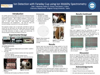
Incorporation of the mechanical gate resulted in sharp peaks (~8
ms wide) corresponding to pulsed ion packets (Figures 9 – 12).
Packets of ions were observed with the same frequency as the
rotating wheel (Figure 11.)
Discussion
Results are promising. The larger wheel is likely needed for
future ion triggering design to be able to determine drift
time. To reduce wobbling and potential charge build-up, an
aluminum wheel will be constructed. A voltage will be
applied to the aluminum wheel to create a more uniform
electric field and the potential to increase ionization voltage.
Signal is expected to increase . Drift gas and temperature
control will also be employed.
Mechanical Gate
• DC Motor (1st Design)
• AC Motor (2nd Design)
• Variable A/C (Staco Energy
Products Co., 3PN1010)
• Cardboard wheels
- 13.1-cm o.d.
- 29.2-cm o.d
Acknowledgements
• BYU-Idaho Chemistry Department
• College of Physical Sciences and Engineering
• BYU-Idaho Mechanical Engineering Department
Results Continued
Figure 2. Top view. Figure 3. Side view.
Figure 4. DC motor with
13.1-cm wheel.
Figure 6. AC motor with
29.2-cm wheel.
Figure 5. Wheel design with
center hole for motor
attachment and slot for ion
passage.
Figure 7. Baseline signal,
no ionization source.
Figure 8. Continuous
signal with ion source.
Peaks were triggered using the oscilloscope in order to
isolate the image of one ion peak (Figures 9,10, and 12).
Implementation of the 29.2-cm o.d. wheel resulted in an
increase in noise, wider peaks, and instability due to
wobbling at low frequency (Not seen in Figure 12).
Figure 9. Signal from
13.1-cm wheel and DC
motor.
Figure 10. Signal from
29.2-cm wheel and DC
motor.
Figure 11. Packets of ions
with same frequency as
29.2-cm wheel .
Figure 1. Ion mobility spectrometer setup.
Figure 12. Signal from
29.2-cm wheel with AC
motor.