SlideShare a Scribd company logo
1 of 6
Download to read offline
Defence Science Journal, Val 44, No 3, July 1994, pp 257-262
@ 1994, DESIDOC
Railgun
S.G. Tatake, K.J. Daniel, K.R. Rao, A.A. Ghosh, and I.I. Khan
ArmamentResearch& DevelopmentEStabliShment,Pune-411021
ABSTRACT
A railgun using electromagnetic propulsion was developed to launch hypervelocity projectiles. A
240kJ, low inductance capacitor bank operating at 5 kV powered the railgun. Launchers and proj~ctiles
were designed and developed for this purpose. The currents producing the launch forces are of the
order of hundreds of kA. Even very low impedances for the current through the railgun circuit are
substantial sources of energy losses. A simulation code was developed to optimise the performance
of the railgun. Control and instrumentation facilities were set up along with a computer-based data
acquisition system for measurement and analysis. The capacity to launch projectiles of3-3.5 9 weight
to a velocity of more than 2.00 km!s was demonstrated. .
NOMENCLAruRE I. INTRODUCTION
A facility was devel6ped to launch hypervelocity
projectiles using electromagnetic energy. The
projectiles were launched using a railgui1. The railgun
consi~ts of two parallel rails and a conducting metanic
foil placed behind the insulating projectile. When a high
current flpws through the rails, the foil explOdes and
forms a plasma armature. The force acting on the
armature is given by
F(t) = 0.50 * L * I (t)2
The railgun currents are in the region of. hundreds
of kA. This Lorentz force accelerates the projectilel-3.
The railgun set-up is shown in Fig. 1.
2. POWER SUPPLY
An electromagnetic propulsion system requires a
storage device with an energy.density comparable to
that of chemic(fl explosives. The most expensive and
technologically difficult part of the system is the
high-energy electric source. The power sources
considered for electromagnetic propulsion are well
4
researched .
A (t) projectile acceleration at time t
Earc(t) energy dissipated in plasma arc at time t
El (t) energy of launcher at time t
Eproj( t) kinetic energy of projectile at time t
Etolal total energy delivered by the power source
F( t) force at time t
I ( t) current through the launcher at time t
L inductance per unit length of the launcher
Leff (t) launcher efficiency at time t
m mass of the projectile
P(t) plasma pressure at time t
PLe((( t) power source to launcher efficiency at time t
S (t) displacement of the projectile at time t
Set(( t) total railgun system efficiency at time t
v( t) velocity of the projectile at time t
Vbr(t) voltage at the breech end of the railgun at time t
Velmz(t) vel()City at the muzzle end of the railgun at time t
Vmvz(t) voltage at the muzzle end()f the railgun at time t
Received 5 march 1993
257
DEF SCI VOL 44, NO 3, JULY 1994
PROJECTILE
ARHAT~E
ROLL
CURRENT ~..-/,/""
(071)
ouTA FIELD
Basic configuration of the railgunFigure 1
2.1 Capacitor Bank and Charging Unit
The capacitor bank was used as a power source
owing to its availability and lower CU"I.despite its lower
energy density5. A low-inductance, 240 kJ capacitor
bank was set up to provide the basic power to the
railgun. A high-voltage charging unit wasusedto charge
the capacitor bank.
Figure 2. Schematic circuit diagram or the railgun powered by the
capacitor bank.
2.2 High Current Switches
Launcher: A simple, single pulse driven railgun
launcher was developed with a minimum of metal
components in proximity to the bore to maximize the
inductance of the launcher and to improve the launch
effici.ency. The launcher has a 12 mm square bore
cross-section. The launcher was fabricated with lengths
ranging from 1 to 2 m. The following launcher designs
were used for the firings:
The capacitor energy is switched into the railgun by
high-power ignitrons. When the peak current is reached,
additionalhigh-power ignitrons are used to crowbar the
capacitors out of the circuit to obtain a dc pulse. This
minimises the stress on the capacitors, the launcher and
the projectile. A schel1}atic diagram of the railgun
powered by the capacitor bank is shown in Fig. 2.
2.3 Transmission Lines The copper rails and the insulater were rigidly
contained within Perspex side plates and bolted.
These launchers were found to be weak, getting
damagedand cracking at higher plasmapressures.
(a)
Low-inductance transmission lines were made using
sandwiched conducting plates to maximize the energy
transfer to the load. The transmission lines are subjected
to repulsive forces owing to the passage of current
through them. These, forces were 'estimated to provide
proper bolting and bracing to avoid deformation of the
transmission lines.
The copper rails and the insulator were rigidly
contained using fibreglaS;sside plates and potted
in an epoxy resin. The assembly was housed in a
cylindrical mild steel jacket.
(b)
The copper rails and the 'insulator were rigidly
contained using fibreglass side plates and wound
with a fibregtass material. They were potted in an
epoxy resin and the assembly was housed in a
cylindrical nonmetallic jacket.
(c)3. LAUNCHER AND PROJECTILE
Launchers and projectiles are subjected to high
plasma pressures. high magnetic fields and high
temperatures. In the present railgun set-up. the plasma
pressures generated varied between 100and 150 MPa.
258
TATAKE et al: RAILGuN
4. DATA ACQUISITION AND SIMULATION
4.1 Data Acquisition
A computei-based data acquisition system was set
up to monitor important parameters that affect the
performance of the railgun. Current transformers and
Rogowski coils were used to measure the rail currents
in the range6of 100 to 500 kA. Magnetic probes were
used to get the position-time profile of the projectile
inside the bore of the gun and railgun current
distribution 7.These probes help detect plasma leakage
and formation of secondary arc. The velocity outsid6
the bore of the gun was measured using shorting
screens8.A high-speed camera was set up to measure
the velocity of the projectile and establish the intt;;grity
of the projectile at the muzzle end. This is a non-contact
method and is free from electromagnetic pickups.
Figure 3. Construction details of the railgun.
4.2 Simulation
A simulation code was developed to predict the
performance of the railgun. The performance of the
model was evaluated by monitoring different
parameters. Table 1 gives the equation used in the
simulation and analysis. The current measured is used
to derive other significant parameters like the
displacement, velocity and acceleration of the projectile
calculated from Eqns (1) -(3).
Table I. t:quations used for the analysis of the railgun system
(I)
(2)
(3)
(4)
(5)
(6)
(7)
(8)
(9)
(10)
(11)
[LI(2.m)] .f fI(tf. dt
[LI(2.m)] .f I(tf.dt
[LI(2.m)] .I(tf
[L.f2] .I(t}2/area
[L.f2] .I(tf
Vb.(t. I(t).dt
E,(t)/E,olal
Epoj (t)/EI (t)
v muz( t) .I ( t) .dt
(1f2) .m. V(t)2
Eproj (t)/E,otaJ
=
=
=
The launchers with the last two design modifications
proved more reliable and durable tha.n the launchers
based on the first design. The details of construction of
the railgun are shown in Fig. 3.
Thermal energy transfer from the rails leads to
ablation and the melting of the bore materials. Such
ablation degrades the performance of the railgun by
adding parasitic massto tHeplasma. The bore materials
should have a high melting point and superior erosion
and ablation resistance. High rail conductivity
necessitated the use of copper rails. Polycarbonate and
fibreglass were most suitable as bore materials. Loose
bore to projectile tolerances or variation in bore
dimensions can result in plasma leakage. Most of the
launchers showed marked deterioration after a few
shots. The deterioration could be attributed to changes
in the bore dimensions due to the rail insulator ablation.
Substantial deposits of carbon were obseIVed inside the
bore of the gun and needed cleaning.
Projectile: The projectiles are made of Perspex or
polycarbonate cubes of 12 mm length. Perspex
projectiles tended to shatter. Polycarbonate projectiles
survived the high plasma pressures.The plasma and the
solid armature were both used for carrying the high
currents. Most firings were carried out using plasma
armature. A plasma armature is formed when AllCu
foil melts/explodes on the passageof high currents. The
foil vaporises by joule heating to produce a plasma to
drive the armature. A neoprene obturator was placed
at the rear of the projectile to seal the bore against
plasma leakage around the projectile. As a deviation,
a solid metallic projectile acting as an armature was
also used to carry the current.
=
5(t)
V(t)
A(t)
P(t)
F(t)
Et(t)
PLdI(t)
LdI(t)
E-(t)
Eproj (t)
5d1(t)
=
=
=
5. ANALYSIS
All measurements were supported by appropriate
software developed to analyse the entire performance
259
DEF SCI J, VOL 44, NO 3, JULY 1994
vnOOTY /IETAII:E ANJ PRO.ECTI.f [ISPlA(D.:NT vs TK
0 ~ NO 1200 1600 2000 2~ 2800 3200 3600 ~000
TM (115)
6. RESULTS
Sometypical railgun trial results are given in Tabl~ 2.
Projectile velocities greater than 2000m/swere obtained
for trial nos 1 to 3. The efficiency varied between 4 to
5 per cent with railgun current in excessof 260 kA.
Plasma leakage and formation 01 secondary arcs8
were responsible for the lower projectile velocities than
expected from the computer model for trial nos 5 to
7. Trial no.7 was done using a solid conducting
projectile made of aluminium. An armature was kept
behind the projectile with no ablator. The armature
vaporised and t;e plasma escaped ahead of the
projectile. This led to a lower system efficiency and
projectile velocity.
A solid projectile made of Perspex and armature
made of several copper foils were used in trial no.4.
The massof each foil was kept around 100mg to avoid
the melting of the armature owing to lne high railgun
current.
7. CONCLUSION
Our study has shown that projectiles attain
hypervelocities by using a single small square bore
railgun. In the existing railgun facility the efficiency
varied between 4 to 5 per cent. Significant improvement
in the efficiency of the railgun set-up is one of the key
issues that will determine the use of railguns for various
weapon applications. Hence we carried out detailed
modelling and simulation of the entire railgun system.
The re5ults from the simulation were validated with the
measurements. Measurements made at high common
mode voltages of around tOOOs of volts and high
electromagnetic noise were exceptic;>nally good,
providing reliable and repeatable records. Intact
projectile launch and 2-3 m of free flight projectile were
studied using high-speed photography when punctures
in1he shorting screens were obsered. Using a high-speed
camera the integl;ity of the projectile was established
beyond doubt (Fig. 5). A 12 mrn cubical polycarbonate
projectile weighing about 3 g could defeat a 6 mm
aluminium sheet at 2 m from the muzzle end of the gun
(Fig. 6). The complete railgun system was also placed
in a 5 m long vacuum chamber to study the railgun
performance. Our studies are as yet i,nconclusive. Owing
to the failure of some odd capacitors in the capacitor
bank, repetitive trials could not be carried using the full
energy of the bank. The energy extracted from the
Ii1gure 4. Projectilevelocityand displacementcomputedfrom the
currentsignalrecordedonscopes.Theinboreandshorting
screenpulseswith respectto timeare alsoshown.
of the railgun. The current-time data are used to predict
the displacement, velocity and acceleration of the
projectile and the plasma pressure. Figure 4 shows the
graphical display of the results derived from the
measurements. N9t only were the measured currents
and the simulated currents compared, but als9 the
results derived from these equations, to validate the
computer model.
The breech and the muzzle voltages are monitored
and along with the current signals are used to estimate
the arc voltage and resistance. The energy of the
launcher and the gun efficiency are als~ computed from
Eqns (6) and (8). The projectile exit at the muzzle is
also indicated on the muzzle voltage signal. The breech
and the muzzle voltage signals aiong with the in-bore
flux probes detected plasma leakages. attributed to low
projectile velocities.
The magnetic flux probes were used to obtain the
displacement of the plasma armature which leads to
in-bore velocity and the acceleration of the projectile
from Eqns (2) -(3). The pl~sma position-time history
and the current signal help estimate the inductance per
unit length of the railgun, a useful input to the simulation
code (Eqn 1).The pulses from the shorting screens were
used to monitor the velocity, acceleration and the
kinetic energy of the projectile outside the bore of the
railgun. There was a substantial agre~ment between the
results predicted from the computer model and the
actual measurements, t.hus validating the simulated
model.
260
TATAKE et sI: RAILGUN
Table 2. Some typical railgun results
-5 6 71 2 3 4Para!J1eter
3.7 3.0 7.0 3.03.0 3.0 3.0
Solid PlasmaPlasma Plasma Solid PlasmaPlasma
155.5 138.24 138.24 138.24138.24 138.24 138.24
267.0
18
271.0
18
287.0
20
234.0
14
298.0
22
296.0
21
290.0
21
740 730 700 491 624 300 466
123 128 143 95154 152 146
1250 22002250 2250 2250 1730 21S0
17()() 588 13002080 2050 2(100 1550
2.566.49 6.30 6.00 4.44 4.35 1.20
4.34 2.58 3.13 0.87 .874.69 4.56
Massof
projectile, 9
Type of
armature
Energy of
bank,kJ
Peak,kA
Peak force on
the projectile, kN
Peak
acceleration on the
projectile, k'g'
Peak
pressure,MPa
Theoretical
projectile
velocity,m/s
Measured
projectile
velocity. m/s
Kinetic
energy of the
projectile, kJ
System
efficiency. %
Figure 5. A polycarbonate projectile photographed through an Imacon high speed camera (framing
speed : 500,000 frames/s; exposure time: 400 ns; flash duration: 500 JIS;and aperture: 4).
261
DEF SCI J, VOL 44, NO 3, JUL y 1994
Pune. for giving us the permission to publish this p,,per.
We are also indebted to him for the facilities that were
made available to us in this Establishment for the
present study.
REFERENCES
1. Rashleigh, S.C. & Marshall, R.A. Electromagnetic
acceleration of macroparticles to high velocities. I.
App. Phy., 198q49,2540-45.
2. Weeks, D.A.; Weldon, W.F. & Zowraka Jr, R.C.
Plasma armature railgun launcher simulations at
University of Texas at Austin. IEEE Trans.
Magnetics, 1989, 25, 580-86.
3. ARDE Closure Report No.892. To establish
technique for launching hypervelocity projectiles,
March 1991.
4. Gully. J.H. Power supply technologies for electric
guns. IEEE Trans. Magnetics, 1991,27,329-34.
5. Rose, M.F. Compact capacitor power railgun
systems.IEEE Trans. Magnetics, 1986,22,1717-21.
6. Pellinen, D.G.; Di Cpana, M.S.; Sampayan, S.E.;
Gerbracht, H. & Wang, M. Rogowskii. Coil for
measuring fast high level pulsed currents. Rev. Sci.
Instrum., 1980,51, 1535-39.
FIgure 6. PenetratIon of the poIycarbonate cuhe through a 6 mm
aluminium sheet at 2 m from the muzzle of the railgun.
Bauer, David P. & Braker, John P. In-bore railgun
p;rojectile velocity. IEEE Trans. Magnetics, 1986,
22, 1395-98.
7-:
capacitor bank varied between 120 and 160 kJ. The
kinetic energy of the projectiles can be incrcascd
substantially by using a higher-energy capacitor bank
as a power source,
.-
T~take, S.G.; Daniel, K.J.; Ghosh, A.A.; Rao,
K.R.; Tokekar, K.P, & Khan, I.I. Diagnostic for
an electromagnetic propulsion system, All India
Conference on Applied Instrumentation, 14-15
February 1992, Roorkee, 275-78.
8.
ACKNOWLEDGEMENTS
We thank Major General D Kapil. Director .
Armament Research and Development Establishment.
262

More Related Content

What's hot

Space Systems & Space Subsystems Fundamentals Technical Training Course Sampler
Space Systems & Space Subsystems Fundamentals Technical Training Course SamplerSpace Systems & Space Subsystems Fundamentals Technical Training Course Sampler
Space Systems & Space Subsystems Fundamentals Technical Training Course SamplerJim Jenkins
 
Ares V: Supporting Space Exploration from LEO to Beyond
Ares V: Supporting Space Exploration from LEO to BeyondAres V: Supporting Space Exploration from LEO to Beyond
Ares V: Supporting Space Exploration from LEO to BeyondAmerican Astronautical Society
 
Undergraduate_Thesis_Dylan_Johnston_10063536
Undergraduate_Thesis_Dylan_Johnston_10063536Undergraduate_Thesis_Dylan_Johnston_10063536
Undergraduate_Thesis_Dylan_Johnston_10063536Dylan Johnston
 
Analysis of Anomalous Thrust Experiments from an Asymmetric Cavity
Analysis of Anomalous Thrust Experiments from an Asymmetric CavityAnalysis of Anomalous Thrust Experiments from an Asymmetric Cavity
Analysis of Anomalous Thrust Experiments from an Asymmetric CavityBrian Kraft
 
EMDrive presentation at Space 08 conference, Barbican, London
EMDrive presentation at Space 08 conference, Barbican, LondonEMDrive presentation at Space 08 conference, Barbican, London
EMDrive presentation at Space 08 conference, Barbican, LondonA. Rocketeer
 
EWSHM2020PRE-PRINTDamageDetectiononanOperatingWindTurbineBladeviaaSingleVibra...
EWSHM2020PRE-PRINTDamageDetectiononanOperatingWindTurbineBladeviaaSingleVibra...EWSHM2020PRE-PRINTDamageDetectiononanOperatingWindTurbineBladeviaaSingleVibra...
EWSHM2020PRE-PRINTDamageDetectiononanOperatingWindTurbineBladeviaaSingleVibra...Tomas Nuñez
 
Impact of Different Wake Models on the Estimation of Wind Farm Power Generation
Impact of Different Wake Models on the Estimation of Wind Farm Power GenerationImpact of Different Wake Models on the Estimation of Wind Farm Power Generation
Impact of Different Wake Models on the Estimation of Wind Farm Power GenerationWeiyang Tong
 
Nir_pres_Hagana_v1
Nir_pres_Hagana_v1Nir_pres_Hagana_v1
Nir_pres_Hagana_v1Nir Morgulis
 
IRJET- Design and Structural Analysis of Torpedo
IRJET- Design and Structural Analysis of TorpedoIRJET- Design and Structural Analysis of Torpedo
IRJET- Design and Structural Analysis of TorpedoIRJET Journal
 
Romiya_HR_presenetation
Romiya_HR_presenetationRomiya_HR_presenetation
Romiya_HR_presenetationRomiya Bose
 
Vcsel Clock.Smith 8.Chou 1
Vcsel Clock.Smith 8.Chou 1Vcsel Clock.Smith 8.Chou 1
Vcsel Clock.Smith 8.Chou 1Clinton Smith
 
study of transponders -Defense Electronics Applications Lab, Dehradun
study of transponders -Defense Electronics Applications Lab, Dehradunstudy of transponders -Defense Electronics Applications Lab, Dehradun
study of transponders -Defense Electronics Applications Lab, DehradunMohit Kumar
 
Communications Payload Design and Satellite System Architecture: Bent Pipe a...
Communications Payload Design and  Satellite System Architecture: Bent Pipe a...Communications Payload Design and  Satellite System Architecture: Bent Pipe a...
Communications Payload Design and Satellite System Architecture: Bent Pipe a...Jim Jenkins
 
Snowmobile mode surveys by ClearView Geophysics Inc.
Snowmobile mode surveys by ClearView Geophysics Inc.Snowmobile mode surveys by ClearView Geophysics Inc.
Snowmobile mode surveys by ClearView Geophysics Inc.JoeMihelcic
 
IRJET- Time-History Analysis of a Cable Stayed Bridge for Various Spans and P...
IRJET- Time-History Analysis of a Cable Stayed Bridge for Various Spans and P...IRJET- Time-History Analysis of a Cable Stayed Bridge for Various Spans and P...
IRJET- Time-History Analysis of a Cable Stayed Bridge for Various Spans and P...IRJET Journal
 

What's hot (17)

Tesi master Yin Meng
Tesi master Yin MengTesi master Yin Meng
Tesi master Yin Meng
 
Space Systems & Space Subsystems Fundamentals Technical Training Course Sampler
Space Systems & Space Subsystems Fundamentals Technical Training Course SamplerSpace Systems & Space Subsystems Fundamentals Technical Training Course Sampler
Space Systems & Space Subsystems Fundamentals Technical Training Course Sampler
 
Ares V: Supporting Space Exploration from LEO to Beyond
Ares V: Supporting Space Exploration from LEO to BeyondAres V: Supporting Space Exploration from LEO to Beyond
Ares V: Supporting Space Exploration from LEO to Beyond
 
Undergraduate_Thesis_Dylan_Johnston_10063536
Undergraduate_Thesis_Dylan_Johnston_10063536Undergraduate_Thesis_Dylan_Johnston_10063536
Undergraduate_Thesis_Dylan_Johnston_10063536
 
Analysis of Anomalous Thrust Experiments from an Asymmetric Cavity
Analysis of Anomalous Thrust Experiments from an Asymmetric CavityAnalysis of Anomalous Thrust Experiments from an Asymmetric Cavity
Analysis of Anomalous Thrust Experiments from an Asymmetric Cavity
 
EMDrive presentation at Space 08 conference, Barbican, London
EMDrive presentation at Space 08 conference, Barbican, LondonEMDrive presentation at Space 08 conference, Barbican, London
EMDrive presentation at Space 08 conference, Barbican, London
 
EWSHM2020PRE-PRINTDamageDetectiononanOperatingWindTurbineBladeviaaSingleVibra...
EWSHM2020PRE-PRINTDamageDetectiononanOperatingWindTurbineBladeviaaSingleVibra...EWSHM2020PRE-PRINTDamageDetectiononanOperatingWindTurbineBladeviaaSingleVibra...
EWSHM2020PRE-PRINTDamageDetectiononanOperatingWindTurbineBladeviaaSingleVibra...
 
Impact of Different Wake Models on the Estimation of Wind Farm Power Generation
Impact of Different Wake Models on the Estimation of Wind Farm Power GenerationImpact of Different Wake Models on the Estimation of Wind Farm Power Generation
Impact of Different Wake Models on the Estimation of Wind Farm Power Generation
 
Nir_pres_Hagana_v1
Nir_pres_Hagana_v1Nir_pres_Hagana_v1
Nir_pres_Hagana_v1
 
IRJET- Design and Structural Analysis of Torpedo
IRJET- Design and Structural Analysis of TorpedoIRJET- Design and Structural Analysis of Torpedo
IRJET- Design and Structural Analysis of Torpedo
 
Romiya_HR_presenetation
Romiya_HR_presenetationRomiya_HR_presenetation
Romiya_HR_presenetation
 
Vcsel Clock.Smith 8.Chou 1
Vcsel Clock.Smith 8.Chou 1Vcsel Clock.Smith 8.Chou 1
Vcsel Clock.Smith 8.Chou 1
 
study of transponders -Defense Electronics Applications Lab, Dehradun
study of transponders -Defense Electronics Applications Lab, Dehradunstudy of transponders -Defense Electronics Applications Lab, Dehradun
study of transponders -Defense Electronics Applications Lab, Dehradun
 
ANL-APS Project.PDF
ANL-APS Project.PDFANL-APS Project.PDF
ANL-APS Project.PDF
 
Communications Payload Design and Satellite System Architecture: Bent Pipe a...
Communications Payload Design and  Satellite System Architecture: Bent Pipe a...Communications Payload Design and  Satellite System Architecture: Bent Pipe a...
Communications Payload Design and Satellite System Architecture: Bent Pipe a...
 
Snowmobile mode surveys by ClearView Geophysics Inc.
Snowmobile mode surveys by ClearView Geophysics Inc.Snowmobile mode surveys by ClearView Geophysics Inc.
Snowmobile mode surveys by ClearView Geophysics Inc.
 
IRJET- Time-History Analysis of a Cable Stayed Bridge for Various Spans and P...
IRJET- Time-History Analysis of a Cable Stayed Bridge for Various Spans and P...IRJET- Time-History Analysis of a Cable Stayed Bridge for Various Spans and P...
IRJET- Time-History Analysis of a Cable Stayed Bridge for Various Spans and P...
 

Similar to EM RAilgun

IJRET-V1I2P1 -Measurement and FEMM Modelling of Experimentally Generated Stro...
IJRET-V1I2P1 -Measurement and FEMM Modelling of Experimentally Generated Stro...IJRET-V1I2P1 -Measurement and FEMM Modelling of Experimentally Generated Stro...
IJRET-V1I2P1 -Measurement and FEMM Modelling of Experimentally Generated Stro...ISAR Publications
 
4.2.cappelli 06(3)
4.2.cappelli 06(3)4.2.cappelli 06(3)
4.2.cappelli 06(3)ELIMENG
 
4.2.cappelli 06(2)
4.2.cappelli 06(2)4.2.cappelli 06(2)
4.2.cappelli 06(2)ELIMENG
 
4.2.cappelli 06(1)
4.2.cappelli 06(1)4.2.cappelli 06(1)
4.2.cappelli 06(1)ELIMENG
 
4.2.cappelli 06
4.2.cappelli 064.2.cappelli 06
4.2.cappelli 06ELIMENG
 
Statistical Quality Control, Lower Tier Suppliers, Automotive Components
Statistical Quality Control, Lower Tier Suppliers, Automotive ComponentsStatistical Quality Control, Lower Tier Suppliers, Automotive Components
Statistical Quality Control, Lower Tier Suppliers, Automotive ComponentsAM Publications
 
Emtp rv ic-part1
Emtp rv ic-part1Emtp rv ic-part1
Emtp rv ic-part1Julian Reis
 
Time-Frequency Representation For Estimating Young’s Modulus and Poisson’s Ra...
Time-Frequency Representation For Estimating Young’s Modulus and Poisson’s Ra...Time-Frequency Representation For Estimating Young’s Modulus and Poisson’s Ra...
Time-Frequency Representation For Estimating Young’s Modulus and Poisson’s Ra...IJERA Editor
 
Simulations of the CNFETs using different high-k gate dielectrics
Simulations of the CNFETs using different high-k gate dielectricsSimulations of the CNFETs using different high-k gate dielectrics
Simulations of the CNFETs using different high-k gate dielectricsjournalBEEI
 
ANALISIS DESAIN SISTEM GRID PENTANAHAN PLTU BERAU KALIMANTAN TIMUR 2 X 7 MW
ANALISIS DESAIN SISTEM GRID PENTANAHAN PLTU BERAU KALIMANTAN TIMUR 2 X 7 MWANALISIS DESAIN SISTEM GRID PENTANAHAN PLTU BERAU KALIMANTAN TIMUR 2 X 7 MW
ANALISIS DESAIN SISTEM GRID PENTANAHAN PLTU BERAU KALIMANTAN TIMUR 2 X 7 MWSyamsirAbduh2
 
Resonant-tunneling-diode effect in Si-based double-barrier structure sputtere...
Resonant-tunneling-diode effect in Si-based double-barrier structure sputtere...Resonant-tunneling-diode effect in Si-based double-barrier structure sputtere...
Resonant-tunneling-diode effect in Si-based double-barrier structure sputtere...IJRES Journal
 
Electro-Mechanical Batteries for low earth orbit satellite with hallow cylind...
Electro-Mechanical Batteries for low earth orbit satellite with hallow cylind...Electro-Mechanical Batteries for low earth orbit satellite with hallow cylind...
Electro-Mechanical Batteries for low earth orbit satellite with hallow cylind...elelijjournal
 
Set and seu analysis of cntfet based designs in harsh environments
Set and seu analysis of cntfet based designs in harsh environmentsSet and seu analysis of cntfet based designs in harsh environments
Set and seu analysis of cntfet based designs in harsh environmentseSAT Publishing House
 
A Study of Thermal Behaviour of HTS Devices at Alternating Current
A Study of Thermal Behaviour of HTS Devices at Alternating Current A Study of Thermal Behaviour of HTS Devices at Alternating Current
A Study of Thermal Behaviour of HTS Devices at Alternating Current IJECEIAES
 
Presentation on energy iter2017 january
Presentation on energy iter2017 januaryPresentation on energy iter2017 january
Presentation on energy iter2017 januaryCooper Lackay
 
Antipodal linearly tapered slot antenna system using substrate parallel plate...
Antipodal linearly tapered slot antenna system using substrate parallel plate...Antipodal linearly tapered slot antenna system using substrate parallel plate...
Antipodal linearly tapered slot antenna system using substrate parallel plate...fanfan he
 

Similar to EM RAilgun (20)

IJRET-V1I2P1 -Measurement and FEMM Modelling of Experimentally Generated Stro...
IJRET-V1I2P1 -Measurement and FEMM Modelling of Experimentally Generated Stro...IJRET-V1I2P1 -Measurement and FEMM Modelling of Experimentally Generated Stro...
IJRET-V1I2P1 -Measurement and FEMM Modelling of Experimentally Generated Stro...
 
4.2.cappelli 06(3)
4.2.cappelli 06(3)4.2.cappelli 06(3)
4.2.cappelli 06(3)
 
4.2.cappelli 06(2)
4.2.cappelli 06(2)4.2.cappelli 06(2)
4.2.cappelli 06(2)
 
4.2.cappelli 06(1)
4.2.cappelli 06(1)4.2.cappelli 06(1)
4.2.cappelli 06(1)
 
4.2.cappelli 06
4.2.cappelli 064.2.cappelli 06
4.2.cappelli 06
 
Statistical Quality Control, Lower Tier Suppliers, Automotive Components
Statistical Quality Control, Lower Tier Suppliers, Automotive ComponentsStatistical Quality Control, Lower Tier Suppliers, Automotive Components
Statistical Quality Control, Lower Tier Suppliers, Automotive Components
 
Emtp rv ic-part1
Emtp rv ic-part1Emtp rv ic-part1
Emtp rv ic-part1
 
Jp3616641669
Jp3616641669Jp3616641669
Jp3616641669
 
Ijsea04021009
Ijsea04021009Ijsea04021009
Ijsea04021009
 
Time-Frequency Representation For Estimating Young’s Modulus and Poisson’s Ra...
Time-Frequency Representation For Estimating Young’s Modulus and Poisson’s Ra...Time-Frequency Representation For Estimating Young’s Modulus and Poisson’s Ra...
Time-Frequency Representation For Estimating Young’s Modulus and Poisson’s Ra...
 
Simulations of the CNFETs using different high-k gate dielectrics
Simulations of the CNFETs using different high-k gate dielectricsSimulations of the CNFETs using different high-k gate dielectrics
Simulations of the CNFETs using different high-k gate dielectrics
 
ANALISIS DESAIN SISTEM GRID PENTANAHAN PLTU BERAU KALIMANTAN TIMUR 2 X 7 MW
ANALISIS DESAIN SISTEM GRID PENTANAHAN PLTU BERAU KALIMANTAN TIMUR 2 X 7 MWANALISIS DESAIN SISTEM GRID PENTANAHAN PLTU BERAU KALIMANTAN TIMUR 2 X 7 MW
ANALISIS DESAIN SISTEM GRID PENTANAHAN PLTU BERAU KALIMANTAN TIMUR 2 X 7 MW
 
Resonant-tunneling-diode effect in Si-based double-barrier structure sputtere...
Resonant-tunneling-diode effect in Si-based double-barrier structure sputtere...Resonant-tunneling-diode effect in Si-based double-barrier structure sputtere...
Resonant-tunneling-diode effect in Si-based double-barrier structure sputtere...
 
Electro-Mechanical Batteries for low earth orbit satellite with hallow cylind...
Electro-Mechanical Batteries for low earth orbit satellite with hallow cylind...Electro-Mechanical Batteries for low earth orbit satellite with hallow cylind...
Electro-Mechanical Batteries for low earth orbit satellite with hallow cylind...
 
Set and seu analysis of cntfet based designs in harsh environments
Set and seu analysis of cntfet based designs in harsh environmentsSet and seu analysis of cntfet based designs in harsh environments
Set and seu analysis of cntfet based designs in harsh environments
 
A Study of Thermal Behaviour of HTS Devices at Alternating Current
A Study of Thermal Behaviour of HTS Devices at Alternating Current A Study of Thermal Behaviour of HTS Devices at Alternating Current
A Study of Thermal Behaviour of HTS Devices at Alternating Current
 
H010526975
H010526975H010526975
H010526975
 
F24034040
F24034040F24034040
F24034040
 
Presentation on energy iter2017 january
Presentation on energy iter2017 januaryPresentation on energy iter2017 january
Presentation on energy iter2017 january
 
Antipodal linearly tapered slot antenna system using substrate parallel plate...
Antipodal linearly tapered slot antenna system using substrate parallel plate...Antipodal linearly tapered slot antenna system using substrate parallel plate...
Antipodal linearly tapered slot antenna system using substrate parallel plate...
 

Recently uploaded

Coefficient of Thermal Expansion and their Importance.pptx
Coefficient of Thermal Expansion and their Importance.pptxCoefficient of Thermal Expansion and their Importance.pptx
Coefficient of Thermal Expansion and their Importance.pptxAsutosh Ranjan
 
Call Girls Service Nashik Vaishnavi 7001305949 Independent Escort Service Nashik
Call Girls Service Nashik Vaishnavi 7001305949 Independent Escort Service NashikCall Girls Service Nashik Vaishnavi 7001305949 Independent Escort Service Nashik
Call Girls Service Nashik Vaishnavi 7001305949 Independent Escort Service NashikCall Girls in Nagpur High Profile
 
(PRIYA) Rajgurunagar Call Girls Just Call 7001035870 [ Cash on Delivery ] Pun...
(PRIYA) Rajgurunagar Call Girls Just Call 7001035870 [ Cash on Delivery ] Pun...(PRIYA) Rajgurunagar Call Girls Just Call 7001035870 [ Cash on Delivery ] Pun...
(PRIYA) Rajgurunagar Call Girls Just Call 7001035870 [ Cash on Delivery ] Pun...ranjana rawat
 
KubeKraft presentation @CloudNativeHooghly
KubeKraft presentation @CloudNativeHooghlyKubeKraft presentation @CloudNativeHooghly
KubeKraft presentation @CloudNativeHooghlysanyuktamishra911
 
Top Rated Pune Call Girls Budhwar Peth ⟟ 6297143586 ⟟ Call Me For Genuine Se...
Top Rated  Pune Call Girls Budhwar Peth ⟟ 6297143586 ⟟ Call Me For Genuine Se...Top Rated  Pune Call Girls Budhwar Peth ⟟ 6297143586 ⟟ Call Me For Genuine Se...
Top Rated Pune Call Girls Budhwar Peth ⟟ 6297143586 ⟟ Call Me For Genuine Se...Call Girls in Nagpur High Profile
 
Porous Ceramics seminar and technical writing
Porous Ceramics seminar and technical writingPorous Ceramics seminar and technical writing
Porous Ceramics seminar and technical writingrakeshbaidya232001
 
(MEERA) Dapodi Call Girls Just Call 7001035870 [ Cash on Delivery ] Pune Escorts
(MEERA) Dapodi Call Girls Just Call 7001035870 [ Cash on Delivery ] Pune Escorts(MEERA) Dapodi Call Girls Just Call 7001035870 [ Cash on Delivery ] Pune Escorts
(MEERA) Dapodi Call Girls Just Call 7001035870 [ Cash on Delivery ] Pune Escortsranjana rawat
 
MANUFACTURING PROCESS-II UNIT-5 NC MACHINE TOOLS
MANUFACTURING PROCESS-II UNIT-5 NC MACHINE TOOLSMANUFACTURING PROCESS-II UNIT-5 NC MACHINE TOOLS
MANUFACTURING PROCESS-II UNIT-5 NC MACHINE TOOLSSIVASHANKAR N
 
Introduction to Multiple Access Protocol.pptx
Introduction to Multiple Access Protocol.pptxIntroduction to Multiple Access Protocol.pptx
Introduction to Multiple Access Protocol.pptxupamatechverse
 
247267395-1-Symmetric-and-distributed-shared-memory-architectures-ppt (1).ppt
247267395-1-Symmetric-and-distributed-shared-memory-architectures-ppt (1).ppt247267395-1-Symmetric-and-distributed-shared-memory-architectures-ppt (1).ppt
247267395-1-Symmetric-and-distributed-shared-memory-architectures-ppt (1).pptssuser5c9d4b1
 
Call for Papers - African Journal of Biological Sciences, E-ISSN: 2663-2187, ...
Call for Papers - African Journal of Biological Sciences, E-ISSN: 2663-2187, ...Call for Papers - African Journal of Biological Sciences, E-ISSN: 2663-2187, ...
Call for Papers - African Journal of Biological Sciences, E-ISSN: 2663-2187, ...Christo Ananth
 
(ANVI) Koregaon Park Call Girls Just Call 7001035870 [ Cash on Delivery ] Pun...
(ANVI) Koregaon Park Call Girls Just Call 7001035870 [ Cash on Delivery ] Pun...(ANVI) Koregaon Park Call Girls Just Call 7001035870 [ Cash on Delivery ] Pun...
(ANVI) Koregaon Park Call Girls Just Call 7001035870 [ Cash on Delivery ] Pun...ranjana rawat
 
UNIT-V FMM.HYDRAULIC TURBINE - Construction and working
UNIT-V FMM.HYDRAULIC TURBINE - Construction and workingUNIT-V FMM.HYDRAULIC TURBINE - Construction and working
UNIT-V FMM.HYDRAULIC TURBINE - Construction and workingrknatarajan
 
Extrusion Processes and Their Limitations
Extrusion Processes and Their LimitationsExtrusion Processes and Their Limitations
Extrusion Processes and Their Limitations120cr0395
 
OSVC_Meta-Data based Simulation Automation to overcome Verification Challenge...
OSVC_Meta-Data based Simulation Automation to overcome Verification Challenge...OSVC_Meta-Data based Simulation Automation to overcome Verification Challenge...
OSVC_Meta-Data based Simulation Automation to overcome Verification Challenge...Soham Mondal
 
IMPLICATIONS OF THE ABOVE HOLISTIC UNDERSTANDING OF HARMONY ON PROFESSIONAL E...
IMPLICATIONS OF THE ABOVE HOLISTIC UNDERSTANDING OF HARMONY ON PROFESSIONAL E...IMPLICATIONS OF THE ABOVE HOLISTIC UNDERSTANDING OF HARMONY ON PROFESSIONAL E...
IMPLICATIONS OF THE ABOVE HOLISTIC UNDERSTANDING OF HARMONY ON PROFESSIONAL E...RajaP95
 
UNIT-II FMM-Flow Through Circular Conduits
UNIT-II FMM-Flow Through Circular ConduitsUNIT-II FMM-Flow Through Circular Conduits
UNIT-II FMM-Flow Through Circular Conduitsrknatarajan
 

Recently uploaded (20)

Coefficient of Thermal Expansion and their Importance.pptx
Coefficient of Thermal Expansion and their Importance.pptxCoefficient of Thermal Expansion and their Importance.pptx
Coefficient of Thermal Expansion and their Importance.pptx
 
Call Girls Service Nashik Vaishnavi 7001305949 Independent Escort Service Nashik
Call Girls Service Nashik Vaishnavi 7001305949 Independent Escort Service NashikCall Girls Service Nashik Vaishnavi 7001305949 Independent Escort Service Nashik
Call Girls Service Nashik Vaishnavi 7001305949 Independent Escort Service Nashik
 
(PRIYA) Rajgurunagar Call Girls Just Call 7001035870 [ Cash on Delivery ] Pun...
(PRIYA) Rajgurunagar Call Girls Just Call 7001035870 [ Cash on Delivery ] Pun...(PRIYA) Rajgurunagar Call Girls Just Call 7001035870 [ Cash on Delivery ] Pun...
(PRIYA) Rajgurunagar Call Girls Just Call 7001035870 [ Cash on Delivery ] Pun...
 
KubeKraft presentation @CloudNativeHooghly
KubeKraft presentation @CloudNativeHooghlyKubeKraft presentation @CloudNativeHooghly
KubeKraft presentation @CloudNativeHooghly
 
Top Rated Pune Call Girls Budhwar Peth ⟟ 6297143586 ⟟ Call Me For Genuine Se...
Top Rated  Pune Call Girls Budhwar Peth ⟟ 6297143586 ⟟ Call Me For Genuine Se...Top Rated  Pune Call Girls Budhwar Peth ⟟ 6297143586 ⟟ Call Me For Genuine Se...
Top Rated Pune Call Girls Budhwar Peth ⟟ 6297143586 ⟟ Call Me For Genuine Se...
 
Porous Ceramics seminar and technical writing
Porous Ceramics seminar and technical writingPorous Ceramics seminar and technical writing
Porous Ceramics seminar and technical writing
 
(MEERA) Dapodi Call Girls Just Call 7001035870 [ Cash on Delivery ] Pune Escorts
(MEERA) Dapodi Call Girls Just Call 7001035870 [ Cash on Delivery ] Pune Escorts(MEERA) Dapodi Call Girls Just Call 7001035870 [ Cash on Delivery ] Pune Escorts
(MEERA) Dapodi Call Girls Just Call 7001035870 [ Cash on Delivery ] Pune Escorts
 
MANUFACTURING PROCESS-II UNIT-5 NC MACHINE TOOLS
MANUFACTURING PROCESS-II UNIT-5 NC MACHINE TOOLSMANUFACTURING PROCESS-II UNIT-5 NC MACHINE TOOLS
MANUFACTURING PROCESS-II UNIT-5 NC MACHINE TOOLS
 
★ CALL US 9953330565 ( HOT Young Call Girls In Badarpur delhi NCR
★ CALL US 9953330565 ( HOT Young Call Girls In Badarpur delhi NCR★ CALL US 9953330565 ( HOT Young Call Girls In Badarpur delhi NCR
★ CALL US 9953330565 ( HOT Young Call Girls In Badarpur delhi NCR
 
Introduction to Multiple Access Protocol.pptx
Introduction to Multiple Access Protocol.pptxIntroduction to Multiple Access Protocol.pptx
Introduction to Multiple Access Protocol.pptx
 
247267395-1-Symmetric-and-distributed-shared-memory-architectures-ppt (1).ppt
247267395-1-Symmetric-and-distributed-shared-memory-architectures-ppt (1).ppt247267395-1-Symmetric-and-distributed-shared-memory-architectures-ppt (1).ppt
247267395-1-Symmetric-and-distributed-shared-memory-architectures-ppt (1).ppt
 
Call for Papers - African Journal of Biological Sciences, E-ISSN: 2663-2187, ...
Call for Papers - African Journal of Biological Sciences, E-ISSN: 2663-2187, ...Call for Papers - African Journal of Biological Sciences, E-ISSN: 2663-2187, ...
Call for Papers - African Journal of Biological Sciences, E-ISSN: 2663-2187, ...
 
(ANVI) Koregaon Park Call Girls Just Call 7001035870 [ Cash on Delivery ] Pun...
(ANVI) Koregaon Park Call Girls Just Call 7001035870 [ Cash on Delivery ] Pun...(ANVI) Koregaon Park Call Girls Just Call 7001035870 [ Cash on Delivery ] Pun...
(ANVI) Koregaon Park Call Girls Just Call 7001035870 [ Cash on Delivery ] Pun...
 
UNIT-V FMM.HYDRAULIC TURBINE - Construction and working
UNIT-V FMM.HYDRAULIC TURBINE - Construction and workingUNIT-V FMM.HYDRAULIC TURBINE - Construction and working
UNIT-V FMM.HYDRAULIC TURBINE - Construction and working
 
Extrusion Processes and Their Limitations
Extrusion Processes and Their LimitationsExtrusion Processes and Their Limitations
Extrusion Processes and Their Limitations
 
Roadmap to Membership of RICS - Pathways and Routes
Roadmap to Membership of RICS - Pathways and RoutesRoadmap to Membership of RICS - Pathways and Routes
Roadmap to Membership of RICS - Pathways and Routes
 
OSVC_Meta-Data based Simulation Automation to overcome Verification Challenge...
OSVC_Meta-Data based Simulation Automation to overcome Verification Challenge...OSVC_Meta-Data based Simulation Automation to overcome Verification Challenge...
OSVC_Meta-Data based Simulation Automation to overcome Verification Challenge...
 
DJARUM4D - SLOT GACOR ONLINE | SLOT DEMO ONLINE
DJARUM4D - SLOT GACOR ONLINE | SLOT DEMO ONLINEDJARUM4D - SLOT GACOR ONLINE | SLOT DEMO ONLINE
DJARUM4D - SLOT GACOR ONLINE | SLOT DEMO ONLINE
 
IMPLICATIONS OF THE ABOVE HOLISTIC UNDERSTANDING OF HARMONY ON PROFESSIONAL E...
IMPLICATIONS OF THE ABOVE HOLISTIC UNDERSTANDING OF HARMONY ON PROFESSIONAL E...IMPLICATIONS OF THE ABOVE HOLISTIC UNDERSTANDING OF HARMONY ON PROFESSIONAL E...
IMPLICATIONS OF THE ABOVE HOLISTIC UNDERSTANDING OF HARMONY ON PROFESSIONAL E...
 
UNIT-II FMM-Flow Through Circular Conduits
UNIT-II FMM-Flow Through Circular ConduitsUNIT-II FMM-Flow Through Circular Conduits
UNIT-II FMM-Flow Through Circular Conduits
 

EM RAilgun

  • 1. Defence Science Journal, Val 44, No 3, July 1994, pp 257-262 @ 1994, DESIDOC Railgun S.G. Tatake, K.J. Daniel, K.R. Rao, A.A. Ghosh, and I.I. Khan ArmamentResearch& DevelopmentEStabliShment,Pune-411021 ABSTRACT A railgun using electromagnetic propulsion was developed to launch hypervelocity projectiles. A 240kJ, low inductance capacitor bank operating at 5 kV powered the railgun. Launchers and proj~ctiles were designed and developed for this purpose. The currents producing the launch forces are of the order of hundreds of kA. Even very low impedances for the current through the railgun circuit are substantial sources of energy losses. A simulation code was developed to optimise the performance of the railgun. Control and instrumentation facilities were set up along with a computer-based data acquisition system for measurement and analysis. The capacity to launch projectiles of3-3.5 9 weight to a velocity of more than 2.00 km!s was demonstrated. . NOMENCLAruRE I. INTRODUCTION A facility was devel6ped to launch hypervelocity projectiles using electromagnetic energy. The projectiles were launched using a railgui1. The railgun consi~ts of two parallel rails and a conducting metanic foil placed behind the insulating projectile. When a high current flpws through the rails, the foil explOdes and forms a plasma armature. The force acting on the armature is given by F(t) = 0.50 * L * I (t)2 The railgun currents are in the region of. hundreds of kA. This Lorentz force accelerates the projectilel-3. The railgun set-up is shown in Fig. 1. 2. POWER SUPPLY An electromagnetic propulsion system requires a storage device with an energy.density comparable to that of chemic(fl explosives. The most expensive and technologically difficult part of the system is the high-energy electric source. The power sources considered for electromagnetic propulsion are well 4 researched . A (t) projectile acceleration at time t Earc(t) energy dissipated in plasma arc at time t El (t) energy of launcher at time t Eproj( t) kinetic energy of projectile at time t Etolal total energy delivered by the power source F( t) force at time t I ( t) current through the launcher at time t L inductance per unit length of the launcher Leff (t) launcher efficiency at time t m mass of the projectile P(t) plasma pressure at time t PLe((( t) power source to launcher efficiency at time t S (t) displacement of the projectile at time t Set(( t) total railgun system efficiency at time t v( t) velocity of the projectile at time t Vbr(t) voltage at the breech end of the railgun at time t Velmz(t) vel()City at the muzzle end of the railgun at time t Vmvz(t) voltage at the muzzle end()f the railgun at time t Received 5 march 1993 257
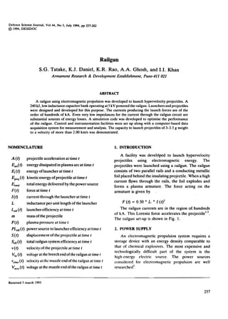
  • 2. DEF SCI VOL 44, NO 3, JULY 1994 PROJECTILE ARHAT~E ROLL CURRENT ~..-/,/"" (071) ouTA FIELD Basic configuration of the railgunFigure 1 2.1 Capacitor Bank and Charging Unit The capacitor bank was used as a power source owing to its availability and lower CU"I.despite its lower energy density5. A low-inductance, 240 kJ capacitor bank was set up to provide the basic power to the railgun. A high-voltage charging unit wasusedto charge the capacitor bank. Figure 2. Schematic circuit diagram or the railgun powered by the capacitor bank. 2.2 High Current Switches Launcher: A simple, single pulse driven railgun launcher was developed with a minimum of metal components in proximity to the bore to maximize the inductance of the launcher and to improve the launch effici.ency. The launcher has a 12 mm square bore cross-section. The launcher was fabricated with lengths ranging from 1 to 2 m. The following launcher designs were used for the firings: The capacitor energy is switched into the railgun by high-power ignitrons. When the peak current is reached, additionalhigh-power ignitrons are used to crowbar the capacitors out of the circuit to obtain a dc pulse. This minimises the stress on the capacitors, the launcher and the projectile. A schel1}atic diagram of the railgun powered by the capacitor bank is shown in Fig. 2. 2.3 Transmission Lines The copper rails and the insulater were rigidly contained within Perspex side plates and bolted. These launchers were found to be weak, getting damagedand cracking at higher plasmapressures. (a) Low-inductance transmission lines were made using sandwiched conducting plates to maximize the energy transfer to the load. The transmission lines are subjected to repulsive forces owing to the passage of current through them. These, forces were 'estimated to provide proper bolting and bracing to avoid deformation of the transmission lines. The copper rails and the insulator were rigidly contained using fibreglaS;sside plates and potted in an epoxy resin. The assembly was housed in a cylindrical mild steel jacket. (b) The copper rails and the 'insulator were rigidly contained using fibreglass side plates and wound with a fibregtass material. They were potted in an epoxy resin and the assembly was housed in a cylindrical nonmetallic jacket. (c)3. LAUNCHER AND PROJECTILE Launchers and projectiles are subjected to high plasma pressures. high magnetic fields and high temperatures. In the present railgun set-up. the plasma pressures generated varied between 100and 150 MPa. 258
  • 3. TATAKE et al: RAILGuN 4. DATA ACQUISITION AND SIMULATION 4.1 Data Acquisition A computei-based data acquisition system was set up to monitor important parameters that affect the performance of the railgun. Current transformers and Rogowski coils were used to measure the rail currents in the range6of 100 to 500 kA. Magnetic probes were used to get the position-time profile of the projectile inside the bore of the gun and railgun current distribution 7.These probes help detect plasma leakage and formation of secondary arc. The velocity outsid6 the bore of the gun was measured using shorting screens8.A high-speed camera was set up to measure the velocity of the projectile and establish the intt;;grity of the projectile at the muzzle end. This is a non-contact method and is free from electromagnetic pickups. Figure 3. Construction details of the railgun. 4.2 Simulation A simulation code was developed to predict the performance of the railgun. The performance of the model was evaluated by monitoring different parameters. Table 1 gives the equation used in the simulation and analysis. The current measured is used to derive other significant parameters like the displacement, velocity and acceleration of the projectile calculated from Eqns (1) -(3). Table I. t:quations used for the analysis of the railgun system (I) (2) (3) (4) (5) (6) (7) (8) (9) (10) (11) [LI(2.m)] .f fI(tf. dt [LI(2.m)] .f I(tf.dt [LI(2.m)] .I(tf [L.f2] .I(t}2/area [L.f2] .I(tf Vb.(t. I(t).dt E,(t)/E,olal Epoj (t)/EI (t) v muz( t) .I ( t) .dt (1f2) .m. V(t)2 Eproj (t)/E,otaJ = = = The launchers with the last two design modifications proved more reliable and durable tha.n the launchers based on the first design. The details of construction of the railgun are shown in Fig. 3. Thermal energy transfer from the rails leads to ablation and the melting of the bore materials. Such ablation degrades the performance of the railgun by adding parasitic massto tHeplasma. The bore materials should have a high melting point and superior erosion and ablation resistance. High rail conductivity necessitated the use of copper rails. Polycarbonate and fibreglass were most suitable as bore materials. Loose bore to projectile tolerances or variation in bore dimensions can result in plasma leakage. Most of the launchers showed marked deterioration after a few shots. The deterioration could be attributed to changes in the bore dimensions due to the rail insulator ablation. Substantial deposits of carbon were obseIVed inside the bore of the gun and needed cleaning. Projectile: The projectiles are made of Perspex or polycarbonate cubes of 12 mm length. Perspex projectiles tended to shatter. Polycarbonate projectiles survived the high plasma pressures.The plasma and the solid armature were both used for carrying the high currents. Most firings were carried out using plasma armature. A plasma armature is formed when AllCu foil melts/explodes on the passageof high currents. The foil vaporises by joule heating to produce a plasma to drive the armature. A neoprene obturator was placed at the rear of the projectile to seal the bore against plasma leakage around the projectile. As a deviation, a solid metallic projectile acting as an armature was also used to carry the current. = 5(t) V(t) A(t) P(t) F(t) Et(t) PLdI(t) LdI(t) E-(t) Eproj (t) 5d1(t) = = = 5. ANALYSIS All measurements were supported by appropriate software developed to analyse the entire performance 259
  • 4. DEF SCI J, VOL 44, NO 3, JULY 1994 vnOOTY /IETAII:E ANJ PRO.ECTI.f [ISPlA(D.:NT vs TK 0 ~ NO 1200 1600 2000 2~ 2800 3200 3600 ~000 TM (115) 6. RESULTS Sometypical railgun trial results are given in Tabl~ 2. Projectile velocities greater than 2000m/swere obtained for trial nos 1 to 3. The efficiency varied between 4 to 5 per cent with railgun current in excessof 260 kA. Plasma leakage and formation 01 secondary arcs8 were responsible for the lower projectile velocities than expected from the computer model for trial nos 5 to 7. Trial no.7 was done using a solid conducting projectile made of aluminium. An armature was kept behind the projectile with no ablator. The armature vaporised and t;e plasma escaped ahead of the projectile. This led to a lower system efficiency and projectile velocity. A solid projectile made of Perspex and armature made of several copper foils were used in trial no.4. The massof each foil was kept around 100mg to avoid the melting of the armature owing to lne high railgun current. 7. CONCLUSION Our study has shown that projectiles attain hypervelocities by using a single small square bore railgun. In the existing railgun facility the efficiency varied between 4 to 5 per cent. Significant improvement in the efficiency of the railgun set-up is one of the key issues that will determine the use of railguns for various weapon applications. Hence we carried out detailed modelling and simulation of the entire railgun system. The re5ults from the simulation were validated with the measurements. Measurements made at high common mode voltages of around tOOOs of volts and high electromagnetic noise were exceptic;>nally good, providing reliable and repeatable records. Intact projectile launch and 2-3 m of free flight projectile were studied using high-speed photography when punctures in1he shorting screens were obsered. Using a high-speed camera the integl;ity of the projectile was established beyond doubt (Fig. 5). A 12 mrn cubical polycarbonate projectile weighing about 3 g could defeat a 6 mm aluminium sheet at 2 m from the muzzle end of the gun (Fig. 6). The complete railgun system was also placed in a 5 m long vacuum chamber to study the railgun performance. Our studies are as yet i,nconclusive. Owing to the failure of some odd capacitors in the capacitor bank, repetitive trials could not be carried using the full energy of the bank. The energy extracted from the Ii1gure 4. Projectilevelocityand displacementcomputedfrom the currentsignalrecordedonscopes.Theinboreandshorting screenpulseswith respectto timeare alsoshown. of the railgun. The current-time data are used to predict the displacement, velocity and acceleration of the projectile and the plasma pressure. Figure 4 shows the graphical display of the results derived from the measurements. N9t only were the measured currents and the simulated currents compared, but als9 the results derived from these equations, to validate the computer model. The breech and the muzzle voltages are monitored and along with the current signals are used to estimate the arc voltage and resistance. The energy of the launcher and the gun efficiency are als~ computed from Eqns (6) and (8). The projectile exit at the muzzle is also indicated on the muzzle voltage signal. The breech and the muzzle voltage signals aiong with the in-bore flux probes detected plasma leakages. attributed to low projectile velocities. The magnetic flux probes were used to obtain the displacement of the plasma armature which leads to in-bore velocity and the acceleration of the projectile from Eqns (2) -(3). The pl~sma position-time history and the current signal help estimate the inductance per unit length of the railgun, a useful input to the simulation code (Eqn 1).The pulses from the shorting screens were used to monitor the velocity, acceleration and the kinetic energy of the projectile outside the bore of the railgun. There was a substantial agre~ment between the results predicted from the computer model and the actual measurements, t.hus validating the simulated model. 260
  • 5. TATAKE et sI: RAILGUN Table 2. Some typical railgun results -5 6 71 2 3 4Para!J1eter 3.7 3.0 7.0 3.03.0 3.0 3.0 Solid PlasmaPlasma Plasma Solid PlasmaPlasma 155.5 138.24 138.24 138.24138.24 138.24 138.24 267.0 18 271.0 18 287.0 20 234.0 14 298.0 22 296.0 21 290.0 21 740 730 700 491 624 300 466 123 128 143 95154 152 146 1250 22002250 2250 2250 1730 21S0 17()() 588 13002080 2050 2(100 1550 2.566.49 6.30 6.00 4.44 4.35 1.20 4.34 2.58 3.13 0.87 .874.69 4.56 Massof projectile, 9 Type of armature Energy of bank,kJ Peak,kA Peak force on the projectile, kN Peak acceleration on the projectile, k'g' Peak pressure,MPa Theoretical projectile velocity,m/s Measured projectile velocity. m/s Kinetic energy of the projectile, kJ System efficiency. % Figure 5. A polycarbonate projectile photographed through an Imacon high speed camera (framing speed : 500,000 frames/s; exposure time: 400 ns; flash duration: 500 JIS;and aperture: 4). 261
  • 6. DEF SCI J, VOL 44, NO 3, JUL y 1994 Pune. for giving us the permission to publish this p,,per. We are also indebted to him for the facilities that were made available to us in this Establishment for the present study. REFERENCES 1. Rashleigh, S.C. & Marshall, R.A. Electromagnetic acceleration of macroparticles to high velocities. I. App. Phy., 198q49,2540-45. 2. Weeks, D.A.; Weldon, W.F. & Zowraka Jr, R.C. Plasma armature railgun launcher simulations at University of Texas at Austin. IEEE Trans. Magnetics, 1989, 25, 580-86. 3. ARDE Closure Report No.892. To establish technique for launching hypervelocity projectiles, March 1991. 4. Gully. J.H. Power supply technologies for electric guns. IEEE Trans. Magnetics, 1991,27,329-34. 5. Rose, M.F. Compact capacitor power railgun systems.IEEE Trans. Magnetics, 1986,22,1717-21. 6. Pellinen, D.G.; Di Cpana, M.S.; Sampayan, S.E.; Gerbracht, H. & Wang, M. Rogowskii. Coil for measuring fast high level pulsed currents. Rev. Sci. Instrum., 1980,51, 1535-39. FIgure 6. PenetratIon of the poIycarbonate cuhe through a 6 mm aluminium sheet at 2 m from the muzzle of the railgun. Bauer, David P. & Braker, John P. In-bore railgun p;rojectile velocity. IEEE Trans. Magnetics, 1986, 22, 1395-98. 7-: capacitor bank varied between 120 and 160 kJ. The kinetic energy of the projectiles can be incrcascd substantially by using a higher-energy capacitor bank as a power source, .- T~take, S.G.; Daniel, K.J.; Ghosh, A.A.; Rao, K.R.; Tokekar, K.P, & Khan, I.I. Diagnostic for an electromagnetic propulsion system, All India Conference on Applied Instrumentation, 14-15 February 1992, Roorkee, 275-78. 8. ACKNOWLEDGEMENTS We thank Major General D Kapil. Director . Armament Research and Development Establishment. 262