Downloaded 12 times
![2
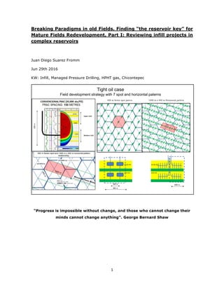
1. Introduction
The Oil and Gas industry has probably endured a permanent change: oil prices might
never recover to 2010-2014 boom prices [1,2]
.
From the Oil and Gas Operators’ point of view, reengineering processes, layoffs,
projects delays, contract negotiations with service providers and operating cost
reductions has been put in action and will likely continue in the near future [3]
.
During this year, the focus has changed from Exploration / Development to that of cost
& production optimization and the upcoming years will probably require greater efforts
in Mature Fields redevelopment.
A well-known technique is that of infill optimization [4,5]
- a field development strategy
that can be defined as “well spacing reduction in order to accelerate and increase
petroleum recovery factor through optimal cost effective and wellbore placement in a
reservoir”.
Some advantages for infill strategy are as follows:
Minimum petroleum system uncertainty. The Petroleum accumulation is proved,
petrophysical / geo-mechanical rock properties, reservoir fluids, downhole
pressures, and base productivity are usually known within a limited range. So
we should be working with 2P reserves development.
Minimum operational risk for specific wellbore designs and some completions
standards used in the field.
On the other hand, some disadvantages include:
Paradigms on field development to be changed;
Field history data availability;
In general, greater subsurface team effort is needed for integration and
evaluation of reservoir models, compared to Appraisal / Initial Field
Development.
Upsides could be overlooked due to paradigms on field development. The
successful one in terms of reserves and cost effective capital expenditure
could be visualized as “finding the key for the field”. But as development
takes place over many years (decades), the “key” should be a dynamic
concept over time, correlated with technology availability, enabling us a
better understanding of petroleum resources size, quality and distribution.
Two field examples will be presented, where after 50 years of development; fresh oil
and gas were produced by changing some reservoir paradigms.](https://image.slidesharecdn.com/revisitinginfillprojects-jdsf-final-160927171022/85/Breaking-Paradigms-in-old-Fields-Finding-the-reservoir-key-for-Mature-Fields-Redevelopment-Part-I-Reviewing-infill-projects-in-complex-reservoirs-2-320.jpg)
![3
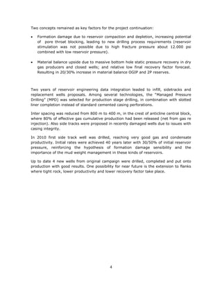
2. Gas & Condensate case
First case is about Mature Gas & Condensate Field in North Argentina. It belongs to
Tarija basin, a Palaeozoic deep thrust belt deposits from Carboniferous geological age
[6,7,8]
.
The reservoir has 3 stratigraphic units, gross thickness is about 400 meters of altering
tight sandstones and shales, in multi faulted anticline structure.
Exploration and appraisal phase started in late 50’s, where main development took
place in 60’s decade with about 60 wells drilled, 70% gas reserves were delimited and
80% were put onto production, achieving 5 years plateau of 180 MMpc/d gas and 7500
bpd condensate. During 70's decade, field production declined as a mature field.
Finally a reinjection gas project was implemented from early 80’s over 20 years due to
low commercial gas value in the region, shutting field production. Meanwhile, field
operator changed in 90’s and started to produce condensate wells, keeping dry gas
injection.
During this time, operators applied good practices reservoir management by
monitoring downhole static and flowing pressures in open and closed wells, producers
and injectors during almost 50 years of history.
After detailed structural settings reinterpretation (integration of surface geology,
seismic markers, well logs and section restoration analysis), the redevelopment started
in late 90’s with the successful appraisal well placement in a new deeper block,
allowing the operator to booked new gas, condensate and oil reserves.
Over 1990 decade, only 5 wells were drilled and put onto production with relative
success due to formation impairment associated with partially depleted regions,
resulting in halting the drilling campaign in 2005.
In the subsequent years, the lack off a consistent productivity / reserves model, turned
out to inconclusive postmortem, increasing technical risk and therefore lowering
economical attractiveness for new wells. So, field started again to decline production,
undergoing for second time the mature stage.](https://image.slidesharecdn.com/revisitinginfillprojects-jdsf-final-160927171022/85/Breaking-Paradigms-in-old-Fields-Finding-the-reservoir-key-for-Mature-Fields-Redevelopment-Part-I-Reviewing-infill-projects-in-complex-reservoirs-3-320.jpg)
![6
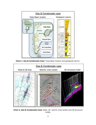
Chart 3. Gas & Condensate Case: Field production & gas re injection history.
Chart 4. Gas & Condensate Case: Ultimate Recovery Factor areal distribution, and
bottom hole reservoir pressure history.
1953 55 57 59 61 63 65 67 69 71 73 75 77 79 81 83 85 87 89 91 93 95 97 99 01 03 05 07 09
10
1
10
2
10
3
10
4
10
5
Date
AREA: CD RESERVORIO: TUP(62)
Gas Rate (Cal. Day) ( Kscm/d )
Oil Rate (Cal. Day) ( m3/d )
Water Rate (Cal. Day) ( m3/d )
Ginj.Cum ( Mscm )
Cumulative Gas Production ( Mscm )
Ginj.CalDay( Kscm/d )
Gas
Condensate
Water
Gas re injection
Main development First Natural decline Gas re injection – condensate prd
Gas & Condensate case
Field gas, condensate and water production & gas re injection history
North
58 – 69 %
R.F. Upside: ≈10%
Central
62 – 69 %
South
57 – 67 %
Yacimiento Campo Durán - Fm Tupambi
Evolución Pws POZOS SELECCIONADOS
(PR 3000 TVDSS)
0
50
100
150
200
250
300
350
400
1/50 12/53 10/57 9/61 8/65 7/69 6/73 5/77 4/81 3/85 2/89 1/93 12/96 11/00 10/04 9/08
Fecha
Pws[kg/cm2]
0
4000
8000
12000
16000
20000
24000
28000
32000
Gef:Gp-Giny[MMm3]
Pws YPF
Pws reiny de gas
Pws Tecpetrol
G efectiva [MMm3]
año 2007: Se produjo todo el gas reinyectadoReinyección de gas 1982 - 2000
año 2009: Extraídos 1000 MMm3 desde el
inicio de la reinyección de gas
1950/77: gas production 1978/2008: gas reinjection/prod
2008: balance
R.F. @ Economic Limit Bottom hole static pressure history
OGIP Upside: ≈25%
Gas & Cond case](https://image.slidesharecdn.com/revisitinginfillprojects-jdsf-final-160927171022/85/Breaking-Paradigms-in-old-Fields-Finding-the-reservoir-key-for-Mature-Fields-Redevelopment-Part-I-Reviewing-infill-projects-in-complex-reservoirs-6-320.jpg)
![8
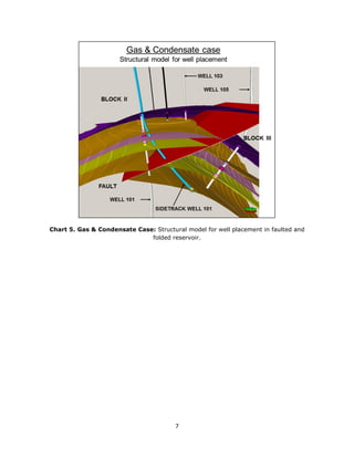
Chart 6. Gas & Condensate Case: Example of reservoir redevelopment:
Replacement well response after 40 years from initial original well production, and
Sidetrack well response after 15 years from initial replacement well production. Initial
productivity of 11 MMpc/d is achieved in spite of reservoir depletion due to successful
mud pressure management during the drilling stage.
Yac. Campo Durán - Fm. Tupambi
Perforación 'Near Balance' en Campo Durán. Proyecto ST CDxp-1001
0
100
200
300
400
500
600
700
1-57 12-60 12-64 12-68 12-72 12-76 12-80 12-84 12-88 12-92 12-96 12-00 12-04 12-08 12-12 12-16 12-20 12-24
Qg[Mm3/d]Qo[m3/d]Np[Mm3]
0
500
1000
1500
2000
2500
3000
3500
Gp[MMm3]
CD-15 Bloque II
(YPF)
ST CDxp-1001
(cuña perforada - pz original)
Julio 2008 CDxp-1001 (merma)
Rotura somera en el casing de producción 9 5/8” (aprox. 500 m) pincha tubing y descarga fluído E/C
csg 13 3/8”-9 5/8” con lodo inverso 1900 g/l – baritina (etapa de perforación de Los Monos)
CDxp-1001 Bloque II & III
(Tecpetrol)
Febrero 2008 CDxp-1001 (recup. Prd)
Limpieza con CTU CaCO3 - pozo vivo HCl 15%+N2
Replacement well after 40 years. Sidetrack after 15 years
First well
(1957)
Reservoir impairment (cement bond break)
Replacement well
(1997)
Live well perforations clean up
HCl jetting with CTU (2007)
Sidetrack well
(2012)
Peak 11 MMpc/d
Gas:Millionscubicmetergas/d,Cond:cubicmeters/d
CondCum:1000cubicmeters
GasCum:Millionscubicmetergas
Gas & Condensate case](https://image.slidesharecdn.com/revisitinginfillprojects-jdsf-final-160927171022/85/Breaking-Paradigms-in-old-Fields-Finding-the-reservoir-key-for-Mature-Fields-Redevelopment-Part-I-Reviewing-infill-projects-in-complex-reservoirs-8-320.jpg)
![9
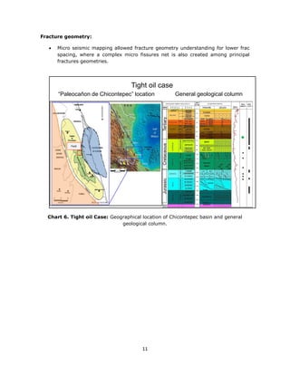
3. Tight Oil case
Second case is a tight oil field located in North Veracruz, Mexico. “Chicontepec Medio”
is a Tertiary reservoir from Tampico-Misantla basin, an important onshore play, and
well known by its low recovery factor and marginal cash flow [9]
.
The reservoir is very complex from structural, stratigraphic and diagenetic point of
view. Extensive and compressive faults systems coexist due to tectonic activity during
deposition of sediments. Characterized by 300 m gross thickness of shallow turbidites,
alternating sandstones and shales, where petro physical properties have been affected
by pore cementing and other diagenesis processes [10]
.
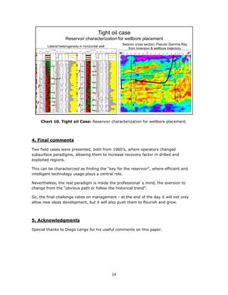
Leading to high vertical and horizontal heterogeneity, the scale of reservoir variations
runs from metres to centimetres.
Some rock quality predictive methods as seismic inversion have been applied with
some success. But appraisal wells are still needed in some regions many decades later
from discovery in order to delimit the reservoirs.
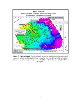
Seven spot pattern with 400 m well spacing has been the field development strategy
for 50 years, showing a great variation on productivity in the same reservoir unit
between adjacent wells, even with good reservoir continuity, according to seismic and
wells correlation. Due to low permeability, hydraulic fractures are needed, leading to
relative low initial productivity and reserves.
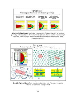
These factors motivated the evaluation of multi fractured horizontal wells, following the
concept of shale gas development strategy.
Challenges for horizontal wells compared to vertical wells:
Shallow reservoirs (low cost for vertical wells).
Reserves distributed in 200 m of layered reservoir (one fractured horizontal well
cannot reach and drain the entire column).
Lateral heterogeneity for horizontal wellbore placement.
Geo mechanical issues in some shale zones. Lack of experience in horizontal
drilling and multifrac completion.
In order to mitigate technical risks, the first horizontal well was planned in the central
part of the field, where higher production and recovery factor has been achieved after
50 years of exploitation. A detailed reservoir characterization and production
performance assessment was achieved due to existing wells.
With this scenario, reservoir pressure was the main risk; keeping in mind that reservoir
target was one of the champion units from the field, leading to potential depletion
issues during drilling, completion, stimulation, and production performance for
horizontal wells.](https://image.slidesharecdn.com/revisitinginfillprojects-jdsf-final-160927171022/85/Breaking-Paradigms-in-old-Fields-Finding-the-reservoir-key-for-Mature-Fields-Redevelopment-Part-I-Reviewing-infill-projects-in-complex-reservoirs-9-320.jpg)
![10
Large amount of data were available but not yet integrated.
An extensive review and reinterpretation took place:
Material balance and decline analysis review.
Update of static model.
Dynamic model construction. History matching for main productive block.
Geo mechanical model was built from compression test in plugs, Young
Modulus, Poisson Modulus, Brightness calculations from logs, fracture gradients
from pre pad test and micro seismic mapping results from previous vertical
wells, seismic inversion correlation with logs (gamma ray, sonic and density).
Main outputs were:
More confidence on final recovery factor for vertical fractured wells and for
projected horizontal multi fractured new wells.
Principal horizontal stress directions and minimum horizontal stress gradients
distributions. Current reservoir pressure distribution.
Greater fracture vertical growing was reinterpreted from old fractured vertical
wells, due to brittleness of rock.
With the above considerations a new static, dynamic, and geo mechanical reservoir
model was built, allowing the ranking of new locations with lower geological risk for
horizontal wellbore placement, along the Minimum Horizontal Stress direction. A robust
fracture design was matched with micro seismic fracture geometry. Also mud weight
window was optimized, allowing better casing depths.
Sensibility scenarios were run with different horizontal length and number of fractures,
finding that 1000 m horizontal length, 400 m spacing between horizontals, and 150 m
fracture spacing are optimal from technical, economical and risk points of view.
The first horizontal drilled well showed excellent results. The second and third
horizontal well were drilled in undeveloped regions, obtaining similar results [11,12,13]
.
The main conclusions were:
Field development:
Initial productivity x 10 times vertical frac well.
Projected ultimate recovery x 8 times vertical frac well.
Projected final oil Recovery Factor increased from 5% to 7%.
Total well cost reduction: 5% respect to seven spot pattern.
Operative Expenditure Costs reduction (including minor workover): 30%
respect to seven spot pattern.
In addition, first horizontal well showed that significant undeveloped reserves
can be produced in drilled zones, in spite of lower reservoir pressure.](https://image.slidesharecdn.com/revisitinginfillprojects-jdsf-final-160927171022/85/Breaking-Paradigms-in-old-Fields-Finding-the-reservoir-key-for-Mature-Fields-Redevelopment-Part-I-Reviewing-infill-projects-in-complex-reservoirs-10-320.jpg)

The document discusses the redevelopment strategies for mature oil and gas fields, emphasizing the importance of infill optimization and innovative drilling techniques. Two case studies are presented: one from a gas and condensate field in Argentina that successfully revitalized production through reinterpretation of reservoir data and managed pressure drilling, and another from a tight oil field in Mexico that explored the effectiveness of horizontal wells in enhancing recovery factors. These examples underline the need for adaptive approaches in the face of changing market conditions and reservoir challenges.


