SlideShare a Scribd company logo
1 of 31
Download to read offline
Centrifugal Pumps:
10.1 Introduction:
Centrifugal pumps are the rotodynamic machines that convert mechanical energy of shaft into
kinetic and pressure energy of water which may be used to raise the level of water. The wheel in
which this conversion is to realized is known as a impeller. A centrifugal pump is named so,
because the energy added by the impeller to the fluid is largely due to centrifugal effects.
The principle of working of centrifugal pumps is same as that of reaction turbines expect that it
works in reverse. Similar to the flow in the reaction turbines, pumps have radial, mixed or axial
flow. Thus a radial-flow pump is the reverse of radial-inward-flow-reaction turbine, a mixed-
flow pump the reverse of a Francis turbine, and an axial-flow pump the reverse of a Kaplan or a
propeller turbine. Recently, reversible type of machines have also been developed which can
work both as a turbine and as a pump.
The shaft of the pump is driven by power from an external source. Energy
provided by the shaft is imparted to the impeller which rotates and transmits this energy to the
liquid. The transfer of energy is given by Euler’s fundamental of energy transfer in hydraulic
machines (Art. 1.7)
According to this equation.
Energy transfer per unit mass
222
222222
 vrriuiui 






----------------------- (10.1)
The first term of this equation represents the change in kinetic energy of the liquid, the second
term the pressure change from centrifugal effects and the third one the static pressure change due
to the relative kinetic energy. The second and the third terms collectively represent static
pressure change in the liquid.
In the radial and the mixed-flow rotodynamic pumps, energy transfer takes transfer takes place
due to all the three effects. But in axial-flow pumps, as the fluid enters and leaves at the same
radial distance from the axis of the impeller, ui-uo and only the first and the third terms of the
equation are effective. Thus in case of axial-flow pumps, no change in the centrifugal energy
takes place. So calling them centrifugal pumps is a misnomer. However, now a days, all
rotodynamic pumps are known as centrifugal pumps in general, though not all of them are
technically so.
In centrifugal pumps, the water enters the impeller through the eye of the pump, a passage along
the shaft at the centre of the impeller, and is pushed towards the periphery by the centrifugal
force. Transfer of energy from the impeller to the fluid takes place which gains in kinetic and
pressure energy. However, high velocity of the leaving water is not desired, as there is energy
loss due to the eddies in the circular chamber that surrounds the vanes. Therefore, the velocity
energy gained in the impeller of a pump is partially converted into useful pressure energy. This is
done by making the leaving water make flow through a passage of gradually increasing area
known as volute or diffuser. This gain in the pressure energy increases the delivery head of the
pumps.
If water supply is maintained at the center, continuous supply of water at high pressure is
obtained at the periphery of the impeller. This may be utilized in delivering water to high
altitudes, in city main supply, in irrigation etc.
Eq. (10.1) may be written in terms of per unit weight i.e. Energy transfer per unit weight
g
vrri
g
uiu
g
i
222
222222
 






-------------------------- (10.2)
The last two terms represents increase in the pressure energy,
H
g
pip
g
i

 2222
2





---------------------------- (10.3)
Where H is the theoretical head to which the liquid is raised and is equal to sum of the velocity
and the pressure heads, assuming the inlet and the outlet of the impeller at same datum. The
actual head is decreased by eddy losses in the pump impeller and passage flow separation, disc
friction, leakage losses etc.
The type of flow in a pump differs from that in a turbine. In a turbine, the flow of liquid is
convergent whereas in a pump it is divergent, i.e. in a turbine; the flow takes place from high
pressure said to low pressure side, and in a pump it is the reverse. In a divergent flow, separation
of flow from the blade profile may occur and the water may leave the blades tangentially. This
may increase the eddy losses, decreasing the efficiency of the pump.
10.2 Classification of Centrifugal Pumps:
Centrifugal pumps may be classified according to,
1. Working head
2. Specific speed
3. Type of casing
4. Direction of flow of water
5. Number of entrances to the impeller
6. Disposition of shaft
7. Number of stage.
1. Working Head.
Centrifugal pumps may be classified in to low, medium and high-head pumps.
(a) Low-Head Centrifugal Pumps.
These are usually single-stage-centrifugal pumps and work below 15m head. Such pumps are use
volute casing without guide vanes. These can be either single-suction or double-suction pumps
with horizontal shafts.
(b) Medium-Head Centrifugal Pumps.
When the head lies between 15 and 45 m, the pumps are called medium-head-centrifugal pumps.
These may or may not be provided with guide vanes, as these are usually single-stage pumps.
Again, these can be either single-suction or double-suction pumps.
(c) High-Head Centrifugal Pumps.
When the head exceeds 45m, the pumps are known as high-head-centrifugal pumps. Usually
these are multistage pumps, and are provided with guide vanes. These pumps may have
horizontal or vertical shafts. Vertical shafts are useful in deep wells.
2. Specified Speed.
Just like turbines, pumps can also be classified on the basis of specific speed specific speed of a
pump is defined as the speed of a geometrically similar pump which delivers unit discharge
under unit head.
N = N√ Q / 4/3
H ---------------------------------- (10.4)
Following table gives the values of specific speed of different types of pumps:
Table 10.1
Pump. Speed Specific Speed
Radial-flow Slow 10-25
Normal 25-45
High 45-70
Mixed-flow 70-135
Axial-flow, Propeller 100-425
3. Types of Casing.
Pumps can be divided into following type according to their casing:
(a) Volute-Chamber Pump.
Such type of casing is of spiral form, and has a sectional area, which increase uniform ally from
the tongue to the delivery pipe as shown in fig.10.1 more area is provided to accommodate
increased quantity of water as the water moves towards the delivery pipe.
Velocity or whirl remains constant through the volute chamber at all cross-sections. Usually, the
value of velocity of whirl in the casing is about 0.4 times the velocity at the impeller outlet. The
impact of the high velocity water leaving the vanes on the slowly moving water in the volute
chamber results in shock losses. Thus utmost care is taken to design the volute casing.
Otherwise, efficiency of conversion of the kinetic energy into the pressure energy will be very
less.
(b) Vortex-chamber Pump.
In a vortex chamber or a whirlpool chamber, a uniformly increasing area is provided between the
impeller outer periphery and the volute casing as shown in fig. 10.2 water, on leaving the
impeller becomes free to adopt its path.
This resembles a free-vortex motion. The increase in area leads to increase in pressure and
decrease in velocity in the outward direction. Water from this chamber is discharged into the
volute casing as usual.
However, in a vortex chamber also, there is instability of flow and eddy formation due to
devergent motion of water. This reduces the efficiency of energy transformation. However, a
vortex chamber is more efficient than a volute chamber.
(c) Diffuser Pump.
In a diffuser Pump, the guide vanes are arranged at the outlet of the impeller vanes. Water enters
the guide without shock. As the guide vanes are of enlarging cros-sectional area, the velocity of
water decreased and pressure increases Since the vanes provide better guidance to flow, eddy
losses are reduced which increases the efficiency. Outside the guide vanes, a collecting volute of
either uniform or increasing cross-sectional area is provided (Fig. 10.3) Sometimes, a diffuser
pump is also known as a turbine pump because with guide vane attachment, it resembles a
reaction turbine.
In case where the condition of working is variable, the water will enter the guide vanes with
shock as there is change in velocity triangles. Thus the diffuser ring can become a source of loss,
reducing the efficiency, in such circumstances, it is better to omit the guide vanes.
Now-a-days, multistage pumps are being provided with guide vane arrangement, whereas single-
stage pumps are of volute or vortex-chamber type.
4. Direction of Flow of Water:
As in reaction turbines, pumps can also have flow as under:
(a) Radial Flow;
Radial flow is one in which the flow in the impeller is completely in a radial direction. This is
used when the requirements are high and low discharge.
(b) Mixed Flow;
As in a mixed-flow turbine, by changing the direction of flow from pure radial to a combination
of a radial and axial, area of flow is increased. Thus mixed-flow pumps are used where medium
discharge is needed to raise the water to medium heads. These are mostly used for irrigation
purposes.
(c) Axial Flow;
It has already been stated that in the strict sense and axial flow pump is not a centrifugal pump.
No centrifugal force is developed as the radial distance of the liquid particles remains constant
from the axis of the impeller. In fact, the vanes of a centrifugal pump are designed. On the basis
of airfoil theory explained in chapter 3. The working of an axial-flow pump is reverse to that of
an axial-flow pump are adjustable, it is called a kapian pump.
These pumps find their use where high discharge at low heads is required, as in irrigation.
Different impeller shapes are shown in Fig. 10.4.
5. Number of Entrances to the Impeller.
Pumps can have either single or double entrance according to the discharge needed.
(a) Single –Suction Pump;
Pumps which have suction pipe only on one side of the impeller are called single-suction pumps
(Fig. 10.5a).
(b) Double-Suction Pump;
In double suction pumps, the suction is made from both sides of the impeller (Fig. 10.5b). This
increases the discharge considerably. Moreover, axial thrust is also neutralized.
6. Disposition of Shaft:
Usually, the centrifugal pumps are used with horizontal shafts. Vertical shafts are used where
there is space limitation i.e. in deep wells, mines etc.
7. Number of Stages:
A centrifugal pump can have a single stage with one impeller keyed to the shaft or it can be a
multi-stage pumps. A multistage pump has a number of impellers mounted on the same shaft and
enclosed in the same casing. These are used to raise high heads and will be discussed in a later
article.
Example 10.1: A double-suction centrifugal pump delivers 2000 litres of
water per second aganst a head of 25 m while running at 725 rmp. What type of impeller
should be used for this pump?
Sol. Considering only one half of the impeller,
H= 25 m Q = 2000/2=1000 lit/s
N= 725rmp = l m
3
/s
Ns = N√ Q / 4/3
H
= 725√1/ (25)3/4
=
64.8
Thus a high-speed radial impeller should be used.
Example: 10.2. A six-centrifugal pumps delivers 0.1 m3
/s against a total head of 480 m.
What is its specific speed if it routes at 1450 rpm ? What type of impeller would you
recommended for the pump?
Sol.
3
1.0 mQ  rmpN 1450
= 480m n = 6
Head developed per impeller,
H = 480/6 = 80 m
Ns = N√ Q / 4/3
H
= 1450 4/3
80/1.0
= 17.14
For this specific speed, low-speed-radial impeller is suitable.
10.3. Components of a Centrifugal Pump
A Centrifugal pump (fig. 10.6) has the following main components:
1. Impeller.
The rotating wheel of a centrifugal pump is called the impeller. It has a number of forward-
curved or backward-curved blades, depending upon whether it is a slow speed or a high speed
impeller. It converts the mechanical energy obtained from some external source through its shaft,
into pressure and velocity energy of water as discussed earlier.
Following are the types of impellers commonly used:
(a) Closed Impeller.
When vanes of the impeller are covered with plates on both sides, it is called a closed impeller.
As it provides better guidance to water, it is more efficient. It can be used when water is free
from external impurities or debris. Otherwise clogging problem will arise.
Material for the impeller will depend on the properties of water. It can be of cast-iron if fresh
water is to be pumped. In such a case an impeller is as one piece and is cheap. When the impeller
is liable to corrosion due to chemical impurities material like stainless-steel and gun metal etc,
may be used impellers that handle hot water more than 140 c are made of cast steel. Pumps for
milk industry are made of stainless-steel to prevent contamination.
(b) Semi-Open Impeller.
(c) When one side of the impeller vanes is covered with a plate, it is a semi-open
impeller. It can be used when the liquid handled is highly viscous or there is
liquid-solid mixture. Such pumps have lesser number of vanes.
(d) Open Impeller.
It is an impeller without cover plate. When the liquid contains some solid suspended matter i.e.
sand paper pulp, molasses etc. the open type of impeller may be used. It has no chance of
clogging.
Different types of impeller are shown in Fig. 10.7.
2. Casing.
As in reaction turbines, there is difference in pressure at the inlet and the outlet of a centrifugal
impeller. So the casing is made air-tight. The casing has provision to support bearing, to fix
stuffing box and to have packing material to prevent leaking. The casing can be split into two
halves along a vertical or a horizontal plane. Vertical-split casing is used for single-suction,
single-stage radial-flow pumps whereas the later is used for all other types such as double-
suction pumps or multistage pumps.
It has already been stated that volute casing is used for single-stage pumps and diffuser casing
for multistage pumps.
3. Suction Pipe.
It is the pipe through which water is lifted from the sump to the pump level. Thus the pipe has its
lower end dipped in the sump water and the upper end is connected to the eye or the inlet of the
pump. At the lower end, a strainer and a foot-valve are also fitted. Foot-valve is an-return valve,
i.e. it does not allow the water to go back to the sump.
Since the pressure at the inlet to the pump is negative and there is fear of cavitations, losses in
the suction pipe should not be high. Many times, the diameter of suction pipe should not be
larger than that of the delivery pipe to reduce the velocity. This reduces friction losses in the
pipe.
4. Delivery Pipe.
It is the pipe which raises the water form the outlet of the pump to the required height. A
delivery valve to regulate the flow is provided in the delivery pipe.
10.4. Starting and Working of a Centrifugal Pump
The centrifugal head developed by a rotating impeller is proportional to the speed of the
other impeller Thus if two similar impellers. One in air and the other in water rotate at
same speed, the centrifugal head developed by the latter will be more, it will also be
consuming more power.
When centrifugal pump is started with the help of a motor, the impeller of the
pump rotates and produces a forced vortex. As long as, the impeller rotates in air, the
centrifugal head developed by the forced vortex will be proportional to the density of the
air. The head will nor be enough to raise the water even a few meters form the sump
level. To develop a sufficient head, the pump has to be felled with water, so that the head
developed by the impeller is enough to raise the liquid to the required height. This
process is called priming and it will be discussed later on.
When the priming is completed and the motor is started, the delivery valve is
closed so that the starting torque is reduced. Now, if the delivery valve is opened and the
speed of the impeller is sufficient, the water will start pouring out of the delivery pipe.
As the water moves towards the periphery, a partial vacuum is created at the eye
of the impeller. Owing to this suction pressure, water form the sump is raised in the
suction pipe, the sump water being under atmospheric pressure. The water leaves the
impeller with high velocity and pressure. The velocity energy is transformed into useful
pressure energy in the impeller casing.
10.5 Heads of a Pump
1. Static Head. It is the vertical distance between water levels in the sump
and the reservoir.
Let stH = Static head on the pump
sh = Height of the centre line of pump above the sump level
(Suction head)
dh = Height of the liquid level in the tank above the centre line
of pump(Delivery head)
Then, H st = sh + .dh
2. Total Head. It is the total head which has to be developed by a pump to
deliver the water form the sump into the tank. Apart from producing the static
head, a pump has also to overcome the losses in pipes and fittings and loss due to
kinetic energy at the delivery outlet.
Let TotalH  head
fsh Losses in suction pip
fdh Losses in delivery pipe
fh Total friction loss in pipe.
= fsh + fsh
V d
= Velocity of liquid in delivery pipe.
Then H = sh + dh +
g
Vd
hfdhfs
2
2

=
g
Vd
hh ds
2
2

Losses in the casing and the impeller are not taken into account in the total head.
Total head is also know as gross head, effective head or dynamic head.
3. Manometric Head.
It is usually not possible to measure exactly the losses in the pump casing. So, a term known as
manometric head is introduced. It is the rise in pressure energy of the liquid in the impeller of the
pump.
If two pressure gauges are installed on the suction and the delivery sides as near to the pump as
possible, the difference in their reading will give the change in the pressure energy in the pump
or the manometric head. (Fig. 10.8)
Let H m = Manometric head of the pump
H ms= Reading of the pressure gauge on the suction side
H md = Reading of the pressure gauge on the delivery side
Vs = Velocity of the liquid in the suction pipe.
Then, H m =H msmd H
Apply Bernoulli’s equation to a point B on the suction side of the pump and to a point A in the
sump where water is still. Assuming point B on the centre line of the pump and taking the sump
level as datum,
H ms +H 00
2
2

g
pa
hfs
g
Vs
s

------------------ (10.6)
Similarly, apply Bernoulli’s equation equation to a point B on the centre line of the pump on the
delivery side and to point C at the discharge end. The difference of height between the centre of
line of the pump and the pressure gauge on the delivery side is neglected.
So that Hmd gives the pressure at the outlet of the pump. Taking the centre line of the pump as
datum,
H md hfdhd
g
Vd
g
pd
g
Vd

2
0
2
22

------------------ (10.7)
Subtracting Eqs. (10.6) from (10.7)
H md
g
p
hfdhd
g
Vd
g
p
hfs
g
Vs
HsH
g
Vd
ms


222
222
H md
g
Vs
HfdHfsHdHsHms
2
2

Hm = Hst + hf +
g
Vs
2
2
----------------------------- (10.8)
Thus the total head of the manometric head differ only in the velocity head. In the former,
velocity head. In the former, velocity head of the delivery pipe is considered while in the latter, it
is the velocity head of the suction pipe. When both pipes are of equal diameter, the total head and
the delivery head becomes equal.
Subtracting Eqs. (10.5) from (10.8)
Hm – H =
g
Vs
2
2
-
g
Vd
2
2
Hm = H + ( )
2
22
g
VdVs 
------------------------- (10.9)
=H when Vs = Vd -------------------------- (10.9a)
It is to be noted that H is the total increase in energy of the liquid by the pump
whereas Hm is the gain in pressure energy only. However, as the difference between Hm and H
is negligible, both can be considered synonymous.
10.6 Energy Conversion in a Centrifugal Pump:
Velocity triangles at the inlet and the outlet of impeller vanes are shown in Fig. 10.9
Let V = Absolute Velocity of water.
u = Tangential Velocity of impeller
Vr = Relative Velocity of water
Vw= Velocity of whirl
Vf = velocity of flow
Subscripts i and o indicate the condition at the inlet and the outlet of the impeller.
Following assumption have been made while deriving the equation for energy conversion in a
centrifugal pump:
1. Impeller consists of infinite number of baldes so that the water is guided on the vane
profiles smoothly
2. No energy loss due to friction and eddy formation
3. No shock losses at the entrance of the vanes
Newton’s second law states that the rate of change of angular momentum (moment of
momentum) of a body is equal to the torque applied. Thus if T is the torque applied on the
impeller.
T = (V )iwiowo rVr  per unit mass
Where ri and ro are the impeller radii at inlet and the outlet respectively.
Energy transfer unit mass
= T.w
= (V )iwiowo rVr  w
= (V )iwiowo uVu 
This is the fundamental equation of energy transfer and is known as Euler’s energy equation.
This can be transformed into the following form.
Energy transfer per unit mass
=
222
22222
VroVriuiuoVVo i 




Meaning of each term has been explained in Art. 10.1
Writing the energy equation in terms of energy transfer per unit weight.
I.e. energy transfer per unit weight
=
g
uVuV iwiowo )( 
This is equal to head developed by the pump and is called Euler head (H0).
In case of reaction turbines, to get maximum work output or energy transfer, value of absolute
velocity at the outlet should be minimum and there should be a radial discharge with no whirl
components. By the same logic, in case of centrifugal pumps, the absolute velocity at the inlet is
made radial with no whirl components so that maximum amount of energy transfer occurs in the
impeller.
Then, Ho =
g
uV owo
The expression shows that to obtain a high head, either uo or Vwo van be increased.
Uo can be increased by increasing the speed of rotation N and diameter Do. Vwo can be
increased by providing sufficient number of vanes of suitable size and shape.
10.7 Variation of Euler Head with vane shapes:
H =
g
Vwouo 
= ][ Vrwouo
g
uo

= ]cot[ 0

 Vfouo
g
uo
-------------------- (10.11)
Where o is the angle of blade tip with the tangent to the rotor as shown in Fig. 10.9.
Q= DoBoVfo
Vfo= Q / DoBo
Hence He = ]cot[ 0

 
DoBo
Q
uo
g
uo
=

 0
2
cot 
DoBog
uoQ
g
uo
If a pump runs at a constant speed,
uo = Constant
Therefore He = C1-C2 Q

0cot 
Where C1 and C2 are constants so that
C1 =
DoBog
uo
andC
g
uo

2,
2
(a) Where  90o ; cot o is negative. The vanes are for ward curved and the
impeller is of slow speed (Fig 10.10a) .H e increase with discharge Q.
(b) When  90o ; cot o = 0. The vanes are radial and the impeller rotates at
medium speed (Fig 10.10b). Euler head H e is constant with discharge and is equal to
,
2
g
uo
(c) Where  90o ;cot o is positive. The vanes are backward curved (fig
10.9). Impeller rotates at a fast speed. He decreases with discharge.
Variation of Euler had H e with discharge Q is shown in Fig. 10.11
Thus head generated is more in case of formed-curved vanes. But as angle o increases, value
of the absolute velocity at the outlet also increases. High values of V are not desired as the
losses. Are increased due to eddies. This results in lowering the efficiency.
10.8 Effect of Finite Number of Canes on Euler Head
In the derivation of the equation for Euler head, it has been assumed that the impeller has
infinite number of vanes so that the water strictly follows the path of the blades profile.
However, in practice, as the impeller must have finite number of vanes, the flow no longer
follows the prescribed path.
In the passage between the two impeller vanes, the velocity distribution can be
considered to be the result of two flows.
1. Uniform velocity distribution, as in case of infinite number of vanes [Fig. 10.12
(a)].
2. Due to inertia, liquid particles are reluctant to turn with the impeller. This result in
high or positive pressure on the loading surface of the vane and low or negative
pressure on the back face. The velocity distribution due to this effect has been
shown in Fig. 10.12 (b).
When these two flows are superimposed, a circulatory or rotational flow is obtained, the
direction of which is opposite to that of the rotation of the impeller [Fig. 10.12 (c)].
The net effect of this circulatory flow is that the water leaves the impeller at an angle lesser than
the blade angle o and the value of the whirl velocity woV is reduced. Change in the outlet
velocity triangle due to finite number of vanes is shown in Fig. 10.13.
Firm lines refer to an impeller with infinite number of canes and dotted lines when the number of
vanes is finite.
Let the reduced value of the whirl velocity be wV  and the reduced
head eH . eH  is usually called input head.
eH  =
g
uVwo 

….(10.12)
Difference between woV and

woV is called slip.
Vane co-efficient  is defined as the ratio of

eH to Euler head

e
H
..ei 


e
e
H
H

woV
V


Value of  depends on the number of vanes, vane angle at the outlet and the ratio of
the radii of the impeller. It is independent of the operating conditions. Following empirical
relation is used to determine the value of  .
 =





o
rirZ
r
sin6.060.0
)(
2
1
1
22
2


Variation of  with number of vanes Z for a radial-flow pump with
ir
o
r = 2 and
Is given in the following table.
Table 10.1
Z 4 6 8 10 14 18 24
 0.62 0.71 0.77 0.81 0.85 0.88 0.91
Value of  becomes unity as Z .o
The reduction of head .eH to

eH due to finite number of vanes is not an actual,
but it is from the failure of the finite number of vanes to impart the relative velocity with
proper angle

 . Thus power input to the pump corresponds to input head .eH and not
.eH
10.9. Losses and Efficiencies
1. Hydraulic Efficiency. Hydraulic losses are the losses the occur between
the suction and the delivery ends of a pump (Fig. 10.14). These include,
(a) Shock losses at the entrance of the impeller vanes and the volute. Whenever a
pump is operated at different working conditions than the designed ones, these losses
would occur as the water does not enter the vanes at the proper angle. Similarly, when the
water enters the volute, there are losses due to the change in velocity as it slows down.
(b) Friction and eddy losses in the vanes and the casing.
(c) Friction and eddy losses in the suction and the delivery pipes.
(d) Losses due to sudden change in the area and the direction of flow.
Hydraulic efficiency takes into account all these losses. It can be defined as the ratio of the
actual or the total head developed and the input head of the pump.
i.e


uV
gH
uV
gH
H
H
h
wo
m
wo
e






(10.14 a )
Hydraulic efficiency varies from 0.6 to 0.9.
2. Manometric Efficiency. As HH  hydraulic efficiency should also be the
manometric efficiency of the pump. However, usually, manometric efficiency is defined as
the hydraulic efficiency of an ideal pump i.e. a pump with infinite number of vanes. Thus,
manometric efficiency is the ratio of the total or the manometric head to the Euler head.
uowoe
man
V
gH
H
H
.

Or
uowo
m
e
m
man
V
gH
H
H
.
 …(10.15)
Also h
H
H
h
H
H
h
H
H
e
e
e
e
e
man 

 

 .. …(10.16)
For infinite number of vanes, 1 and hydraulic efficiency becomes equal to
manometric efficiency and the two terms become synonymous.
Problems, where nothing is mentioned of the effect of the finite number of canes, are
generally, solved on the assumption that the impeller has infinite number of vanes and 1 .
Thus no distinction is made between the hydraulic efficiency and the manometric efficiency
and we have,
man  =
 .wV
gH
…(10.17)
3. Volumetric Efficiency. The pressure at the outlet of the impeller is higher than at
the inlet. Thus there is always a tendency on the part of water to slip back or leak back
through the clearance between the impeller and the casing. There can also be some leakage
from the seals. These are called volumetric losses.
Volumetric efficiency is the ratio of the actual discharge to the total discharge.
Q = Amount of discharge
Let
.
QQ
Q
Q
v




Amount of leakage.
Its value lies between 0.97 and 0.98.
4. Mechanical Efficiency. Mechanical losses in case of a pump are due to
(a) Friction in bearings and glands
(b) Disc friction as the impeller rotates in liquid. Some authors prefer to include the
disc friction loss in the hydraulic losses.
Mechanical efficiency is the ratio of the actual power input to the impeller and the
power given to the shaft.
Let  Total power input to the shaft
 P=Mechanical losses
Then
P
uVQQ
P
PP wo
m






)(
 …(10.19)
Its value lies between 95-98 %.
5. Overall Efficiency. It is the ratio of the total head developed by a pump to the total
power input to the shaft.
i.e.
P
QgH
  …(10.20)
P
uVQQ
QQ
Q
guV
H wo
wo









)(
/

.mvh   …(10.21)
When number of vanes is infinite
manh  
Then
P
uVQQ
QQ
Q
guV
H wo
wo



)(
/






mvman   …(10.22)
Range of overall efficiency is between 0.71 to 0.86.
Various losses have been shown in Fig. 10.15.
uV
gH
H
H
P
P
QQ
Q
P
P
woe
h
v














uV
gH
H
H
wo
e
h 

 for infinite number of vanes
P
PP
P
P
m




P
QgH
P
P 
 


Example 10.3. A centrifugal pump discharges 0.13 sm /2
when running at a speed of
1450 rmp. Head developed is 30 m. Impeller diameter and width at the outlet are 30 cm 5 cm
respectively. Hydraulic efficiency is 77%. Find vane angles at the outer periphery of the
impeller.
Sol H=30m Q=0.13 sm /3
D o =0.30 m N= 1450 rmp
B =0.05 m h =0.77.
From outlet velocity triangle,
Tan

 =
rwo
fo
V
V
wo
fo
Vu
V



Where 60
DoN
u 

=
60
14503.0 
=22.78 m/s
And foV and woV are evaluated as below,
Q = DoBoVfo
0.13= Vfo 05.03.0
Vfo = 2.76 m/s
owo
h
uV
gH

0.77 =
78.22
3081.9


woV
woV = 16.78 m/s
Tan

 = 46.0
78.1678.22
76.2



 = 24 24 
Example 10.4. A centrifugal pump works against a head of 25m and discharges 0.22 m3
/s
while running at 1000 rpm. Velocity of flow at the outlet is 2.8 m/s and the outlet angle of the
vane is 30
. Determine the diameter and the width of the impeller at the outlet. Take hydraulic
efficiency as 78%.
Solution.
H = 25m Q = 0.22 m3/s
N = 1000 rpm foV = 2.8 m
h = 0.78

 = 30
u
60
DoN
o


From this relation Do can be evaluated if we have known u . To evaluate u , we have,
woo
h
Vu
gH

)( rwboo Vuu
gH


=
)cot(

 fooo Vuu
gH
Or 0.77=
)30cot8.2(
2581.9



oo uu
=
uouo 85.4
2581.9
2


Or uouo 85.4
2
 =314.5
22
)
2
85.4
()
2
85.4
.(2  uouo
=314.5+ 2
)
2
85.4
(
22
)89.17()425.2( uo ---------- Fig (10.17)
Or uo =17.89+2.425
= 20.315 m/s
20.315 =
60
1000Do
Do= 0.388 m or 38.8 cm.
Q = DoBoVfo
0.22 = 8.239.0  B
B =0.064 m or 6.4 cm
In Fig 10.17, Consider the vane shape at inlet tangent to

riV
Example 10.5 A centrifugal pumps delivers 50 liters of water per second to a height of
15m through a 20 m long pipe. Diameter of the pipe is 14 cm. Overall efficiency is 72 %, and the
coefficient of friction 0.015. Determine the power needed to drive the pump.
Sol. 15sH m Q=0.05 m3
/s
I = 20 m f = 0.015
d = 0.14 m o = 72%
 =
P
pQgH
…Eq (10.20)
We have,
g
V
hHH d
fs
2
2
 …Eq (10.5)
For which dV is given by,
dVdQ .
4
2

dV.)14.0(
4
05.0 2

Or dV = 3.25 m/s
And
dg
fIV
h d
f


2
4 2
=
14.081.92
25.320015.04 2


= 4.61 m
 H=15+4.61+
81.92
25.3 2

= 20.15 m
 0.72=
P
15.2081.905.01000 
Or P = 13726 W
= 13.726 k W.
10.15. Multistage Pumps
To develop a high head, the tangential speed ou has to be increased. However an
increase in the speed also increases the stresses in the impeller material. This implies that
centrifugal pump with one impeller cannot be used to raise high heads.
More than one pump is needed to develop a high head. The discharge of one
pump is delivered to the next to further augment the head.
However, a better way is to mount two or more impellers on the same shaft and
enclose them in the same cashing. All the impellers are put in series so that the water coming out
of one impeller is directed to the next impeller and so on (Fig. 10.22). Guide vanes are used to
guide the water from one impeller to another and to convert some of the kinetic energy into the
pressure energy. Thus, pressure energy of the water increases continuously both in the impeller
and in the guide vanes. Kinetic energy is brought back to the same level while passing through
the guide vanes. The pressure and the velocity variations over the stages are shown in Fig. 10.23.
10.16 Pumps in Parallel
Many times, it is desired to augment the flow at normal heads.
This can be achieved by arranging more than one pump in parallel as shown in Fig. 10.24. Each
pump lifts the water from the common sump and discharges into a common delivery pipe. Each
pump delivers the liquid against the same head. Total discharge is given by the sum of
discharges of individual pumps.
i.e. nQQQQQr .........321 
10.17. Primary Devices
In Art. 10.4, it was stated that to start a pump, it has to be filled with water
so that the eentri8fugal head developed is sufficient to lift the water from the sump. The process
is known as priming.
Usually, the suction pipe is provided with a foot-valve or a non-return valve to
obviate the necessity of priming, each time a pump is started. However, if a pump is being
started after a long period, the water could have leaked out of the pump. So every time a check
has to be made. An air-vent is provide in the pump casing so that the air may escape through it
white water is being poured in. Following methods are usually employed to prime a pump.
1. External-Priming Devices
(a) The pump and the suction pipe may by filled with water with a funnel.
(b) A chamber may be provided on the delivery side to store water to be used later for
priming.
(c) A vacuum creating device may be used to create enough vacuum in the pump to
raise the water in the suction pipe.
2. Self-Priming Devices
(a) Priming with Separator. Density of water is 800 times of what of air.
So, the head generated by the impeller in air is lesser in the same ratio. In this method of self
priming, the density of air is increased by mixing it with water so increase the head generated.
10.18. Performance of Centrifugal Pumps
A pump similar to a turbine, is designed for particular values of speed,
Head and discharge and the pump have maximum efficiency at these designed values. But a
pump may have to work under different conditions than the designed one. With change in one
parameter, others are affected. Characteristic curves are helpful in predicting the behavior of
pump under different parameters.
Following curves are usually drawn for centrifugal pumps:
1. Main characteristic curves
2. Operating characteristic curves
3. Constant-head and constant-discharge curves
4. Constant-efficiency curves
1. Main Characteristic Curves. In order to plot main characteristic curves, the pump is
run at a particular speed. The discharge is varied with the help of the delivery valve and the
corresponding values of head, power and efficiency are found out. The procedure is repeated
by keeping the speed constant at different values.

More Related Content

What's hot (20)

Centrifugal Pumps
Centrifugal PumpsCentrifugal Pumps
Centrifugal Pumps
 
Centrifugal Pumps
Centrifugal PumpsCentrifugal Pumps
Centrifugal Pumps
 
Turbine.ppt
Turbine.pptTurbine.ppt
Turbine.ppt
 
application of Direction control valve in automatic transmission
application of Direction control valve in automatic transmissionapplication of Direction control valve in automatic transmission
application of Direction control valve in automatic transmission
 
Fluid mechanics
Fluid mechanics Fluid mechanics
Fluid mechanics
 
Hydraulic Pumps
Hydraulic PumpsHydraulic Pumps
Hydraulic Pumps
 
Centrifugal pumps
Centrifugal pumpsCentrifugal pumps
Centrifugal pumps
 
Pump design presentation
Pump design presentationPump design presentation
Pump design presentation
 
Hydraulic circuits
Hydraulic circuitsHydraulic circuits
Hydraulic circuits
 
Hydraulic Turbines
Hydraulic TurbinesHydraulic Turbines
Hydraulic Turbines
 
Selection of pumps in oil industry
Selection of pumps in oil industrySelection of pumps in oil industry
Selection of pumps in oil industry
 
Fluid Mechanics and Turbo Design ch2
Fluid Mechanics and Turbo Design ch2Fluid Mechanics and Turbo Design ch2
Fluid Mechanics and Turbo Design ch2
 
Pumps and piping
Pumps and pipingPumps and piping
Pumps and piping
 
Centrifugal pump
Centrifugal pumpCentrifugal pump
Centrifugal pump
 
Hydraulic Pump
Hydraulic PumpHydraulic Pump
Hydraulic Pump
 
Impulse turbine
Impulse turbineImpulse turbine
Impulse turbine
 
5. francis turbine
5. francis turbine5. francis turbine
5. francis turbine
 
Pump total basics
Pump total basicsPump total basics
Pump total basics
 
Hydraulics & pneumatics (AU) unit-I
Hydraulics & pneumatics (AU)   unit-IHydraulics & pneumatics (AU)   unit-I
Hydraulics & pneumatics (AU) unit-I
 
Centrifugal pumps
Centrifugal pumpsCentrifugal pumps
Centrifugal pumps
 

Similar to Centrifugal pumps

Centrifugal & reciprocating pumps
Centrifugal & reciprocating  pumpsCentrifugal & reciprocating  pumps
Centrifugal & reciprocating pumpsvishalgohel12195
 
turbine in plant
turbine in plantturbine in plant
turbine in plantNaman Meena
 
hydraulic-machines.pptx
hydraulic-machines.pptxhydraulic-machines.pptx
hydraulic-machines.pptxAnoopYadhav
 
Centrifugal pumps e_notes_dr_n_balasubra
Centrifugal pumps e_notes_dr_n_balasubraCentrifugal pumps e_notes_dr_n_balasubra
Centrifugal pumps e_notes_dr_n_balasubraManoj Shukla
 
K 10716 mukesh beniwal (centrifugal pumps working as turbine)
K 10716 mukesh beniwal (centrifugal pumps working as turbine)K 10716 mukesh beniwal (centrifugal pumps working as turbine)
K 10716 mukesh beniwal (centrifugal pumps working as turbine)shailesh yadav
 
Centrifugal pump
Centrifugal pumpCentrifugal pump
Centrifugal pumpKawinKit
 
Detailed presentation on pumps
Detailed presentation on pumpsDetailed presentation on pumps
Detailed presentation on pumpsAmmar Qazi
 
Description about working with sketches of: Reciprocating pump, Centrifugal...
Description about  working with sketches  of: Reciprocating pump, Centrifugal...Description about  working with sketches  of: Reciprocating pump, Centrifugal...
Description about working with sketches of: Reciprocating pump, Centrifugal...Anish mon T.S
 
Turbines and recipocating pumps and miscellaneous hydraulic machines
Turbines and recipocating pumps and miscellaneous hydraulic machinesTurbines and recipocating pumps and miscellaneous hydraulic machines
Turbines and recipocating pumps and miscellaneous hydraulic machinesMohit Yadav
 
Centrifugal and gear pump theory dms
Centrifugal and gear pump theory dmsCentrifugal and gear pump theory dms
Centrifugal and gear pump theory dmsSagar Dhotare
 
hydraulicmachines-200422173920.pdf
hydraulicmachines-200422173920.pdfhydraulicmachines-200422173920.pdf
hydraulicmachines-200422173920.pdfChandreshTripathi6
 

Similar to Centrifugal pumps (20)

Centrifugal pumps
Centrifugal pumpsCentrifugal pumps
Centrifugal pumps
 
Centrifugal & reciprocating pumps
Centrifugal & reciprocating  pumpsCentrifugal & reciprocating  pumps
Centrifugal & reciprocating pumps
 
turbine in plant
turbine in plantturbine in plant
turbine in plant
 
hydraulic-machines.pptx
hydraulic-machines.pptxhydraulic-machines.pptx
hydraulic-machines.pptx
 
FM_Cluster 6.pptx
FM_Cluster 6.pptxFM_Cluster 6.pptx
FM_Cluster 6.pptx
 
Centrifugal pumps e_notes_dr_n_balasubra
Centrifugal pumps e_notes_dr_n_balasubraCentrifugal pumps e_notes_dr_n_balasubra
Centrifugal pumps e_notes_dr_n_balasubra
 
Torbomachinery zbj
Torbomachinery zbjTorbomachinery zbj
Torbomachinery zbj
 
HM (M3).pptx
HM (M3).pptxHM (M3).pptx
HM (M3).pptx
 
adasdad
adasdadadasdad
adasdad
 
22dsad
22dsad22dsad
22dsad
 
K 10716 mukesh beniwal (centrifugal pumps working as turbine)
K 10716 mukesh beniwal (centrifugal pumps working as turbine)K 10716 mukesh beniwal (centrifugal pumps working as turbine)
K 10716 mukesh beniwal (centrifugal pumps working as turbine)
 
Centrifugal pump
Centrifugal pumpCentrifugal pump
Centrifugal pump
 
Regenerative turbine pump application, design, and features
Regenerative turbine pump application, design, and featuresRegenerative turbine pump application, design, and features
Regenerative turbine pump application, design, and features
 
Centrifugal pump
Centrifugal pumpCentrifugal pump
Centrifugal pump
 
Centrifugal pumps
Centrifugal pumpsCentrifugal pumps
Centrifugal pumps
 
Detailed presentation on pumps
Detailed presentation on pumpsDetailed presentation on pumps
Detailed presentation on pumps
 
Description about working with sketches of: Reciprocating pump, Centrifugal...
Description about  working with sketches  of: Reciprocating pump, Centrifugal...Description about  working with sketches  of: Reciprocating pump, Centrifugal...
Description about working with sketches of: Reciprocating pump, Centrifugal...
 
Turbines and recipocating pumps and miscellaneous hydraulic machines
Turbines and recipocating pumps and miscellaneous hydraulic machinesTurbines and recipocating pumps and miscellaneous hydraulic machines
Turbines and recipocating pumps and miscellaneous hydraulic machines
 
Centrifugal and gear pump theory dms
Centrifugal and gear pump theory dmsCentrifugal and gear pump theory dms
Centrifugal and gear pump theory dms
 
hydraulicmachines-200422173920.pdf
hydraulicmachines-200422173920.pdfhydraulicmachines-200422173920.pdf
hydraulicmachines-200422173920.pdf
 

Recently uploaded

GDSC ASEB Gen AI study jams presentation
GDSC ASEB Gen AI study jams presentationGDSC ASEB Gen AI study jams presentation
GDSC ASEB Gen AI study jams presentationGDSCAESB
 
Coefficient of Thermal Expansion and their Importance.pptx
Coefficient of Thermal Expansion and their Importance.pptxCoefficient of Thermal Expansion and their Importance.pptx
Coefficient of Thermal Expansion and their Importance.pptxAsutosh Ranjan
 
Current Transformer Drawing and GTP for MSETCL
Current Transformer Drawing and GTP for MSETCLCurrent Transformer Drawing and GTP for MSETCL
Current Transformer Drawing and GTP for MSETCLDeelipZope
 
High Profile Call Girls Nashik Megha 7001305949 Independent Escort Service Na...
High Profile Call Girls Nashik Megha 7001305949 Independent Escort Service Na...High Profile Call Girls Nashik Megha 7001305949 Independent Escort Service Na...
High Profile Call Girls Nashik Megha 7001305949 Independent Escort Service Na...Call Girls in Nagpur High Profile
 
VIP Call Girls Service Hitech City Hyderabad Call +91-8250192130
VIP Call Girls Service Hitech City Hyderabad Call +91-8250192130VIP Call Girls Service Hitech City Hyderabad Call +91-8250192130
VIP Call Girls Service Hitech City Hyderabad Call +91-8250192130Suhani Kapoor
 
247267395-1-Symmetric-and-distributed-shared-memory-architectures-ppt (1).ppt
247267395-1-Symmetric-and-distributed-shared-memory-architectures-ppt (1).ppt247267395-1-Symmetric-and-distributed-shared-memory-architectures-ppt (1).ppt
247267395-1-Symmetric-and-distributed-shared-memory-architectures-ppt (1).pptssuser5c9d4b1
 
Internship report on mechanical engineering
Internship report on mechanical engineeringInternship report on mechanical engineering
Internship report on mechanical engineeringmalavadedarshan25
 
Microscopic Analysis of Ceramic Materials.pptx
Microscopic Analysis of Ceramic Materials.pptxMicroscopic Analysis of Ceramic Materials.pptx
Microscopic Analysis of Ceramic Materials.pptxpurnimasatapathy1234
 
Introduction to IEEE STANDARDS and its different types.pptx
Introduction to IEEE STANDARDS and its different types.pptxIntroduction to IEEE STANDARDS and its different types.pptx
Introduction to IEEE STANDARDS and its different types.pptxupamatechverse
 
OSVC_Meta-Data based Simulation Automation to overcome Verification Challenge...
OSVC_Meta-Data based Simulation Automation to overcome Verification Challenge...OSVC_Meta-Data based Simulation Automation to overcome Verification Challenge...
OSVC_Meta-Data based Simulation Automation to overcome Verification Challenge...Soham Mondal
 
HARMONY IN THE NATURE AND EXISTENCE - Unit-IV
HARMONY IN THE NATURE AND EXISTENCE - Unit-IVHARMONY IN THE NATURE AND EXISTENCE - Unit-IV
HARMONY IN THE NATURE AND EXISTENCE - Unit-IVRajaP95
 
ZXCTN 5804 / ZTE PTN / ZTE POTN / ZTE 5804 PTN / ZTE POTN 5804 ( 100/200 GE Z...
ZXCTN 5804 / ZTE PTN / ZTE POTN / ZTE 5804 PTN / ZTE POTN 5804 ( 100/200 GE Z...ZXCTN 5804 / ZTE PTN / ZTE POTN / ZTE 5804 PTN / ZTE POTN 5804 ( 100/200 GE Z...
ZXCTN 5804 / ZTE PTN / ZTE POTN / ZTE 5804 PTN / ZTE POTN 5804 ( 100/200 GE Z...ZTE
 
Processing & Properties of Floor and Wall Tiles.pptx
Processing & Properties of Floor and Wall Tiles.pptxProcessing & Properties of Floor and Wall Tiles.pptx
Processing & Properties of Floor and Wall Tiles.pptxpranjaldaimarysona
 
Structural Analysis and Design of Foundations: A Comprehensive Handbook for S...
Structural Analysis and Design of Foundations: A Comprehensive Handbook for S...Structural Analysis and Design of Foundations: A Comprehensive Handbook for S...
Structural Analysis and Design of Foundations: A Comprehensive Handbook for S...Dr.Costas Sachpazis
 
MANUFACTURING PROCESS-II UNIT-5 NC MACHINE TOOLS
MANUFACTURING PROCESS-II UNIT-5 NC MACHINE TOOLSMANUFACTURING PROCESS-II UNIT-5 NC MACHINE TOOLS
MANUFACTURING PROCESS-II UNIT-5 NC MACHINE TOOLSSIVASHANKAR N
 
(MEERA) Dapodi Call Girls Just Call 7001035870 [ Cash on Delivery ] Pune Escorts
(MEERA) Dapodi Call Girls Just Call 7001035870 [ Cash on Delivery ] Pune Escorts(MEERA) Dapodi Call Girls Just Call 7001035870 [ Cash on Delivery ] Pune Escorts
(MEERA) Dapodi Call Girls Just Call 7001035870 [ Cash on Delivery ] Pune Escortsranjana rawat
 
High Profile Call Girls Nagpur Meera Call 7001035870 Meet With Nagpur Escorts
High Profile Call Girls Nagpur Meera Call 7001035870 Meet With Nagpur EscortsHigh Profile Call Girls Nagpur Meera Call 7001035870 Meet With Nagpur Escorts
High Profile Call Girls Nagpur Meera Call 7001035870 Meet With Nagpur EscortsCall Girls in Nagpur High Profile
 

Recently uploaded (20)

GDSC ASEB Gen AI study jams presentation
GDSC ASEB Gen AI study jams presentationGDSC ASEB Gen AI study jams presentation
GDSC ASEB Gen AI study jams presentation
 
Coefficient of Thermal Expansion and their Importance.pptx
Coefficient of Thermal Expansion and their Importance.pptxCoefficient of Thermal Expansion and their Importance.pptx
Coefficient of Thermal Expansion and their Importance.pptx
 
Current Transformer Drawing and GTP for MSETCL
Current Transformer Drawing and GTP for MSETCLCurrent Transformer Drawing and GTP for MSETCL
Current Transformer Drawing and GTP for MSETCL
 
High Profile Call Girls Nashik Megha 7001305949 Independent Escort Service Na...
High Profile Call Girls Nashik Megha 7001305949 Independent Escort Service Na...High Profile Call Girls Nashik Megha 7001305949 Independent Escort Service Na...
High Profile Call Girls Nashik Megha 7001305949 Independent Escort Service Na...
 
Call Us -/9953056974- Call Girls In Vikaspuri-/- Delhi NCR
Call Us -/9953056974- Call Girls In Vikaspuri-/- Delhi NCRCall Us -/9953056974- Call Girls In Vikaspuri-/- Delhi NCR
Call Us -/9953056974- Call Girls In Vikaspuri-/- Delhi NCR
 
VIP Call Girls Service Hitech City Hyderabad Call +91-8250192130
VIP Call Girls Service Hitech City Hyderabad Call +91-8250192130VIP Call Girls Service Hitech City Hyderabad Call +91-8250192130
VIP Call Girls Service Hitech City Hyderabad Call +91-8250192130
 
247267395-1-Symmetric-and-distributed-shared-memory-architectures-ppt (1).ppt
247267395-1-Symmetric-and-distributed-shared-memory-architectures-ppt (1).ppt247267395-1-Symmetric-and-distributed-shared-memory-architectures-ppt (1).ppt
247267395-1-Symmetric-and-distributed-shared-memory-architectures-ppt (1).ppt
 
Internship report on mechanical engineering
Internship report on mechanical engineeringInternship report on mechanical engineering
Internship report on mechanical engineering
 
★ CALL US 9953330565 ( HOT Young Call Girls In Badarpur delhi NCR
★ CALL US 9953330565 ( HOT Young Call Girls In Badarpur delhi NCR★ CALL US 9953330565 ( HOT Young Call Girls In Badarpur delhi NCR
★ CALL US 9953330565 ( HOT Young Call Girls In Badarpur delhi NCR
 
Microscopic Analysis of Ceramic Materials.pptx
Microscopic Analysis of Ceramic Materials.pptxMicroscopic Analysis of Ceramic Materials.pptx
Microscopic Analysis of Ceramic Materials.pptx
 
Introduction to IEEE STANDARDS and its different types.pptx
Introduction to IEEE STANDARDS and its different types.pptxIntroduction to IEEE STANDARDS and its different types.pptx
Introduction to IEEE STANDARDS and its different types.pptx
 
OSVC_Meta-Data based Simulation Automation to overcome Verification Challenge...
OSVC_Meta-Data based Simulation Automation to overcome Verification Challenge...OSVC_Meta-Data based Simulation Automation to overcome Verification Challenge...
OSVC_Meta-Data based Simulation Automation to overcome Verification Challenge...
 
HARMONY IN THE NATURE AND EXISTENCE - Unit-IV
HARMONY IN THE NATURE AND EXISTENCE - Unit-IVHARMONY IN THE NATURE AND EXISTENCE - Unit-IV
HARMONY IN THE NATURE AND EXISTENCE - Unit-IV
 
DJARUM4D - SLOT GACOR ONLINE | SLOT DEMO ONLINE
DJARUM4D - SLOT GACOR ONLINE | SLOT DEMO ONLINEDJARUM4D - SLOT GACOR ONLINE | SLOT DEMO ONLINE
DJARUM4D - SLOT GACOR ONLINE | SLOT DEMO ONLINE
 
ZXCTN 5804 / ZTE PTN / ZTE POTN / ZTE 5804 PTN / ZTE POTN 5804 ( 100/200 GE Z...
ZXCTN 5804 / ZTE PTN / ZTE POTN / ZTE 5804 PTN / ZTE POTN 5804 ( 100/200 GE Z...ZXCTN 5804 / ZTE PTN / ZTE POTN / ZTE 5804 PTN / ZTE POTN 5804 ( 100/200 GE Z...
ZXCTN 5804 / ZTE PTN / ZTE POTN / ZTE 5804 PTN / ZTE POTN 5804 ( 100/200 GE Z...
 
Processing & Properties of Floor and Wall Tiles.pptx
Processing & Properties of Floor and Wall Tiles.pptxProcessing & Properties of Floor and Wall Tiles.pptx
Processing & Properties of Floor and Wall Tiles.pptx
 
Structural Analysis and Design of Foundations: A Comprehensive Handbook for S...
Structural Analysis and Design of Foundations: A Comprehensive Handbook for S...Structural Analysis and Design of Foundations: A Comprehensive Handbook for S...
Structural Analysis and Design of Foundations: A Comprehensive Handbook for S...
 
MANUFACTURING PROCESS-II UNIT-5 NC MACHINE TOOLS
MANUFACTURING PROCESS-II UNIT-5 NC MACHINE TOOLSMANUFACTURING PROCESS-II UNIT-5 NC MACHINE TOOLS
MANUFACTURING PROCESS-II UNIT-5 NC MACHINE TOOLS
 
(MEERA) Dapodi Call Girls Just Call 7001035870 [ Cash on Delivery ] Pune Escorts
(MEERA) Dapodi Call Girls Just Call 7001035870 [ Cash on Delivery ] Pune Escorts(MEERA) Dapodi Call Girls Just Call 7001035870 [ Cash on Delivery ] Pune Escorts
(MEERA) Dapodi Call Girls Just Call 7001035870 [ Cash on Delivery ] Pune Escorts
 
High Profile Call Girls Nagpur Meera Call 7001035870 Meet With Nagpur Escorts
High Profile Call Girls Nagpur Meera Call 7001035870 Meet With Nagpur EscortsHigh Profile Call Girls Nagpur Meera Call 7001035870 Meet With Nagpur Escorts
High Profile Call Girls Nagpur Meera Call 7001035870 Meet With Nagpur Escorts
 

Centrifugal pumps

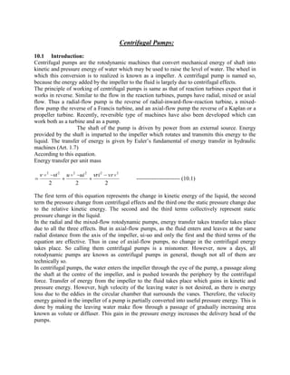
  • 1. Centrifugal Pumps: 10.1 Introduction: Centrifugal pumps are the rotodynamic machines that convert mechanical energy of shaft into kinetic and pressure energy of water which may be used to raise the level of water. The wheel in which this conversion is to realized is known as a impeller. A centrifugal pump is named so, because the energy added by the impeller to the fluid is largely due to centrifugal effects. The principle of working of centrifugal pumps is same as that of reaction turbines expect that it works in reverse. Similar to the flow in the reaction turbines, pumps have radial, mixed or axial flow. Thus a radial-flow pump is the reverse of radial-inward-flow-reaction turbine, a mixed- flow pump the reverse of a Francis turbine, and an axial-flow pump the reverse of a Kaplan or a propeller turbine. Recently, reversible type of machines have also been developed which can work both as a turbine and as a pump. The shaft of the pump is driven by power from an external source. Energy provided by the shaft is imparted to the impeller which rotates and transmits this energy to the liquid. The transfer of energy is given by Euler’s fundamental of energy transfer in hydraulic machines (Art. 1.7) According to this equation. Energy transfer per unit mass 222 222222  vrriuiui        ----------------------- (10.1) The first term of this equation represents the change in kinetic energy of the liquid, the second term the pressure change from centrifugal effects and the third one the static pressure change due to the relative kinetic energy. The second and the third terms collectively represent static pressure change in the liquid. In the radial and the mixed-flow rotodynamic pumps, energy transfer takes transfer takes place due to all the three effects. But in axial-flow pumps, as the fluid enters and leaves at the same radial distance from the axis of the impeller, ui-uo and only the first and the third terms of the equation are effective. Thus in case of axial-flow pumps, no change in the centrifugal energy takes place. So calling them centrifugal pumps is a misnomer. However, now a days, all rotodynamic pumps are known as centrifugal pumps in general, though not all of them are technically so. In centrifugal pumps, the water enters the impeller through the eye of the pump, a passage along the shaft at the centre of the impeller, and is pushed towards the periphery by the centrifugal force. Transfer of energy from the impeller to the fluid takes place which gains in kinetic and pressure energy. However, high velocity of the leaving water is not desired, as there is energy loss due to the eddies in the circular chamber that surrounds the vanes. Therefore, the velocity energy gained in the impeller of a pump is partially converted into useful pressure energy. This is done by making the leaving water make flow through a passage of gradually increasing area known as volute or diffuser. This gain in the pressure energy increases the delivery head of the pumps.
  • 2. If water supply is maintained at the center, continuous supply of water at high pressure is obtained at the periphery of the impeller. This may be utilized in delivering water to high altitudes, in city main supply, in irrigation etc. Eq. (10.1) may be written in terms of per unit weight i.e. Energy transfer per unit weight g vrri g uiu g i 222 222222         -------------------------- (10.2) The last two terms represents increase in the pressure energy, H g pip g i   2222 2      ---------------------------- (10.3) Where H is the theoretical head to which the liquid is raised and is equal to sum of the velocity and the pressure heads, assuming the inlet and the outlet of the impeller at same datum. The actual head is decreased by eddy losses in the pump impeller and passage flow separation, disc friction, leakage losses etc. The type of flow in a pump differs from that in a turbine. In a turbine, the flow of liquid is convergent whereas in a pump it is divergent, i.e. in a turbine; the flow takes place from high pressure said to low pressure side, and in a pump it is the reverse. In a divergent flow, separation of flow from the blade profile may occur and the water may leave the blades tangentially. This may increase the eddy losses, decreasing the efficiency of the pump. 10.2 Classification of Centrifugal Pumps: Centrifugal pumps may be classified according to, 1. Working head 2. Specific speed 3. Type of casing 4. Direction of flow of water 5. Number of entrances to the impeller 6. Disposition of shaft 7. Number of stage. 1. Working Head. Centrifugal pumps may be classified in to low, medium and high-head pumps. (a) Low-Head Centrifugal Pumps. These are usually single-stage-centrifugal pumps and work below 15m head. Such pumps are use volute casing without guide vanes. These can be either single-suction or double-suction pumps with horizontal shafts.
  • 3. (b) Medium-Head Centrifugal Pumps. When the head lies between 15 and 45 m, the pumps are called medium-head-centrifugal pumps. These may or may not be provided with guide vanes, as these are usually single-stage pumps. Again, these can be either single-suction or double-suction pumps. (c) High-Head Centrifugal Pumps. When the head exceeds 45m, the pumps are known as high-head-centrifugal pumps. Usually these are multistage pumps, and are provided with guide vanes. These pumps may have horizontal or vertical shafts. Vertical shafts are useful in deep wells. 2. Specified Speed. Just like turbines, pumps can also be classified on the basis of specific speed specific speed of a pump is defined as the speed of a geometrically similar pump which delivers unit discharge under unit head. N = N√ Q / 4/3 H ---------------------------------- (10.4) Following table gives the values of specific speed of different types of pumps: Table 10.1 Pump. Speed Specific Speed Radial-flow Slow 10-25 Normal 25-45 High 45-70 Mixed-flow 70-135 Axial-flow, Propeller 100-425 3. Types of Casing. Pumps can be divided into following type according to their casing: (a) Volute-Chamber Pump. Such type of casing is of spiral form, and has a sectional area, which increase uniform ally from the tongue to the delivery pipe as shown in fig.10.1 more area is provided to accommodate increased quantity of water as the water moves towards the delivery pipe.
  • 4. Velocity or whirl remains constant through the volute chamber at all cross-sections. Usually, the value of velocity of whirl in the casing is about 0.4 times the velocity at the impeller outlet. The impact of the high velocity water leaving the vanes on the slowly moving water in the volute chamber results in shock losses. Thus utmost care is taken to design the volute casing. Otherwise, efficiency of conversion of the kinetic energy into the pressure energy will be very less. (b) Vortex-chamber Pump. In a vortex chamber or a whirlpool chamber, a uniformly increasing area is provided between the impeller outer periphery and the volute casing as shown in fig. 10.2 water, on leaving the impeller becomes free to adopt its path.
  • 5. This resembles a free-vortex motion. The increase in area leads to increase in pressure and decrease in velocity in the outward direction. Water from this chamber is discharged into the volute casing as usual. However, in a vortex chamber also, there is instability of flow and eddy formation due to devergent motion of water. This reduces the efficiency of energy transformation. However, a vortex chamber is more efficient than a volute chamber. (c) Diffuser Pump. In a diffuser Pump, the guide vanes are arranged at the outlet of the impeller vanes. Water enters the guide without shock. As the guide vanes are of enlarging cros-sectional area, the velocity of water decreased and pressure increases Since the vanes provide better guidance to flow, eddy losses are reduced which increases the efficiency. Outside the guide vanes, a collecting volute of either uniform or increasing cross-sectional area is provided (Fig. 10.3) Sometimes, a diffuser pump is also known as a turbine pump because with guide vane attachment, it resembles a reaction turbine. In case where the condition of working is variable, the water will enter the guide vanes with shock as there is change in velocity triangles. Thus the diffuser ring can become a source of loss, reducing the efficiency, in such circumstances, it is better to omit the guide vanes.
  • 6. Now-a-days, multistage pumps are being provided with guide vane arrangement, whereas single- stage pumps are of volute or vortex-chamber type. 4. Direction of Flow of Water: As in reaction turbines, pumps can also have flow as under: (a) Radial Flow; Radial flow is one in which the flow in the impeller is completely in a radial direction. This is used when the requirements are high and low discharge.
  • 7. (b) Mixed Flow; As in a mixed-flow turbine, by changing the direction of flow from pure radial to a combination of a radial and axial, area of flow is increased. Thus mixed-flow pumps are used where medium discharge is needed to raise the water to medium heads. These are mostly used for irrigation purposes. (c) Axial Flow; It has already been stated that in the strict sense and axial flow pump is not a centrifugal pump. No centrifugal force is developed as the radial distance of the liquid particles remains constant from the axis of the impeller. In fact, the vanes of a centrifugal pump are designed. On the basis of airfoil theory explained in chapter 3. The working of an axial-flow pump is reverse to that of an axial-flow pump are adjustable, it is called a kapian pump. These pumps find their use where high discharge at low heads is required, as in irrigation. Different impeller shapes are shown in Fig. 10.4. 5. Number of Entrances to the Impeller. Pumps can have either single or double entrance according to the discharge needed. (a) Single –Suction Pump; Pumps which have suction pipe only on one side of the impeller are called single-suction pumps (Fig. 10.5a). (b) Double-Suction Pump; In double suction pumps, the suction is made from both sides of the impeller (Fig. 10.5b). This increases the discharge considerably. Moreover, axial thrust is also neutralized.
  • 8. 6. Disposition of Shaft: Usually, the centrifugal pumps are used with horizontal shafts. Vertical shafts are used where there is space limitation i.e. in deep wells, mines etc. 7. Number of Stages: A centrifugal pump can have a single stage with one impeller keyed to the shaft or it can be a multi-stage pumps. A multistage pump has a number of impellers mounted on the same shaft and enclosed in the same casing. These are used to raise high heads and will be discussed in a later article. Example 10.1: A double-suction centrifugal pump delivers 2000 litres of water per second aganst a head of 25 m while running at 725 rmp. What type of impeller should be used for this pump? Sol. Considering only one half of the impeller, H= 25 m Q = 2000/2=1000 lit/s N= 725rmp = l m 3 /s Ns = N√ Q / 4/3 H = 725√1/ (25)3/4 = 64.8 Thus a high-speed radial impeller should be used. Example: 10.2. A six-centrifugal pumps delivers 0.1 m3 /s against a total head of 480 m. What is its specific speed if it routes at 1450 rpm ? What type of impeller would you recommended for the pump? Sol. 3 1.0 mQ  rmpN 1450 = 480m n = 6 Head developed per impeller, H = 480/6 = 80 m Ns = N√ Q / 4/3 H = 1450 4/3 80/1.0 = 17.14 For this specific speed, low-speed-radial impeller is suitable.
  • 9. 10.3. Components of a Centrifugal Pump A Centrifugal pump (fig. 10.6) has the following main components: 1. Impeller. The rotating wheel of a centrifugal pump is called the impeller. It has a number of forward- curved or backward-curved blades, depending upon whether it is a slow speed or a high speed impeller. It converts the mechanical energy obtained from some external source through its shaft, into pressure and velocity energy of water as discussed earlier. Following are the types of impellers commonly used: (a) Closed Impeller. When vanes of the impeller are covered with plates on both sides, it is called a closed impeller. As it provides better guidance to water, it is more efficient. It can be used when water is free from external impurities or debris. Otherwise clogging problem will arise. Material for the impeller will depend on the properties of water. It can be of cast-iron if fresh water is to be pumped. In such a case an impeller is as one piece and is cheap. When the impeller is liable to corrosion due to chemical impurities material like stainless-steel and gun metal etc, may be used impellers that handle hot water more than 140 c are made of cast steel. Pumps for milk industry are made of stainless-steel to prevent contamination.
  • 10. (b) Semi-Open Impeller. (c) When one side of the impeller vanes is covered with a plate, it is a semi-open impeller. It can be used when the liquid handled is highly viscous or there is liquid-solid mixture. Such pumps have lesser number of vanes. (d) Open Impeller. It is an impeller without cover plate. When the liquid contains some solid suspended matter i.e. sand paper pulp, molasses etc. the open type of impeller may be used. It has no chance of clogging. Different types of impeller are shown in Fig. 10.7. 2. Casing. As in reaction turbines, there is difference in pressure at the inlet and the outlet of a centrifugal impeller. So the casing is made air-tight. The casing has provision to support bearing, to fix stuffing box and to have packing material to prevent leaking. The casing can be split into two halves along a vertical or a horizontal plane. Vertical-split casing is used for single-suction, single-stage radial-flow pumps whereas the later is used for all other types such as double- suction pumps or multistage pumps. It has already been stated that volute casing is used for single-stage pumps and diffuser casing for multistage pumps. 3. Suction Pipe. It is the pipe through which water is lifted from the sump to the pump level. Thus the pipe has its lower end dipped in the sump water and the upper end is connected to the eye or the inlet of the pump. At the lower end, a strainer and a foot-valve are also fitted. Foot-valve is an-return valve, i.e. it does not allow the water to go back to the sump. Since the pressure at the inlet to the pump is negative and there is fear of cavitations, losses in the suction pipe should not be high. Many times, the diameter of suction pipe should not be larger than that of the delivery pipe to reduce the velocity. This reduces friction losses in the pipe.
  • 11. 4. Delivery Pipe. It is the pipe which raises the water form the outlet of the pump to the required height. A delivery valve to regulate the flow is provided in the delivery pipe. 10.4. Starting and Working of a Centrifugal Pump The centrifugal head developed by a rotating impeller is proportional to the speed of the other impeller Thus if two similar impellers. One in air and the other in water rotate at same speed, the centrifugal head developed by the latter will be more, it will also be consuming more power. When centrifugal pump is started with the help of a motor, the impeller of the pump rotates and produces a forced vortex. As long as, the impeller rotates in air, the centrifugal head developed by the forced vortex will be proportional to the density of the air. The head will nor be enough to raise the water even a few meters form the sump level. To develop a sufficient head, the pump has to be felled with water, so that the head developed by the impeller is enough to raise the liquid to the required height. This process is called priming and it will be discussed later on. When the priming is completed and the motor is started, the delivery valve is closed so that the starting torque is reduced. Now, if the delivery valve is opened and the speed of the impeller is sufficient, the water will start pouring out of the delivery pipe. As the water moves towards the periphery, a partial vacuum is created at the eye of the impeller. Owing to this suction pressure, water form the sump is raised in the suction pipe, the sump water being under atmospheric pressure. The water leaves the impeller with high velocity and pressure. The velocity energy is transformed into useful pressure energy in the impeller casing. 10.5 Heads of a Pump 1. Static Head. It is the vertical distance between water levels in the sump and the reservoir. Let stH = Static head on the pump sh = Height of the centre line of pump above the sump level (Suction head) dh = Height of the liquid level in the tank above the centre line of pump(Delivery head) Then, H st = sh + .dh 2. Total Head. It is the total head which has to be developed by a pump to deliver the water form the sump into the tank. Apart from producing the static head, a pump has also to overcome the losses in pipes and fittings and loss due to kinetic energy at the delivery outlet. Let TotalH  head
  • 12. fsh Losses in suction pip fdh Losses in delivery pipe fh Total friction loss in pipe. = fsh + fsh V d = Velocity of liquid in delivery pipe. Then H = sh + dh + g Vd hfdhfs 2 2  = g Vd hh ds 2 2  Losses in the casing and the impeller are not taken into account in the total head. Total head is also know as gross head, effective head or dynamic head. 3. Manometric Head. It is usually not possible to measure exactly the losses in the pump casing. So, a term known as manometric head is introduced. It is the rise in pressure energy of the liquid in the impeller of the pump. If two pressure gauges are installed on the suction and the delivery sides as near to the pump as possible, the difference in their reading will give the change in the pressure energy in the pump or the manometric head. (Fig. 10.8) Let H m = Manometric head of the pump H ms= Reading of the pressure gauge on the suction side H md = Reading of the pressure gauge on the delivery side Vs = Velocity of the liquid in the suction pipe. Then, H m =H msmd H Apply Bernoulli’s equation to a point B on the suction side of the pump and to a point A in the sump where water is still. Assuming point B on the centre line of the pump and taking the sump level as datum, H ms +H 00 2 2  g pa hfs g Vs s  ------------------ (10.6) Similarly, apply Bernoulli’s equation equation to a point B on the centre line of the pump on the delivery side and to point C at the discharge end. The difference of height between the centre of line of the pump and the pressure gauge on the delivery side is neglected.
  • 13. So that Hmd gives the pressure at the outlet of the pump. Taking the centre line of the pump as datum, H md hfdhd g Vd g pd g Vd  2 0 2 22  ------------------ (10.7) Subtracting Eqs. (10.6) from (10.7) H md g p hfdhd g Vd g p hfs g Vs HsH g Vd ms   222 222 H md g Vs HfdHfsHdHsHms 2 2  Hm = Hst + hf + g Vs 2 2 ----------------------------- (10.8) Thus the total head of the manometric head differ only in the velocity head. In the former, velocity head. In the former, velocity head of the delivery pipe is considered while in the latter, it
  • 14. is the velocity head of the suction pipe. When both pipes are of equal diameter, the total head and the delivery head becomes equal. Subtracting Eqs. (10.5) from (10.8) Hm – H = g Vs 2 2 - g Vd 2 2 Hm = H + ( ) 2 22 g VdVs  ------------------------- (10.9) =H when Vs = Vd -------------------------- (10.9a) It is to be noted that H is the total increase in energy of the liquid by the pump whereas Hm is the gain in pressure energy only. However, as the difference between Hm and H is negligible, both can be considered synonymous. 10.6 Energy Conversion in a Centrifugal Pump: Velocity triangles at the inlet and the outlet of impeller vanes are shown in Fig. 10.9 Let V = Absolute Velocity of water. u = Tangential Velocity of impeller Vr = Relative Velocity of water Vw= Velocity of whirl Vf = velocity of flow Subscripts i and o indicate the condition at the inlet and the outlet of the impeller. Following assumption have been made while deriving the equation for energy conversion in a centrifugal pump: 1. Impeller consists of infinite number of baldes so that the water is guided on the vane profiles smoothly 2. No energy loss due to friction and eddy formation 3. No shock losses at the entrance of the vanes
  • 15. Newton’s second law states that the rate of change of angular momentum (moment of momentum) of a body is equal to the torque applied. Thus if T is the torque applied on the impeller. T = (V )iwiowo rVr  per unit mass Where ri and ro are the impeller radii at inlet and the outlet respectively. Energy transfer unit mass = T.w = (V )iwiowo rVr  w = (V )iwiowo uVu  This is the fundamental equation of energy transfer and is known as Euler’s energy equation. This can be transformed into the following form. Energy transfer per unit mass = 222 22222 VroVriuiuoVVo i      Meaning of each term has been explained in Art. 10.1 Writing the energy equation in terms of energy transfer per unit weight. I.e. energy transfer per unit weight = g uVuV iwiowo )(  This is equal to head developed by the pump and is called Euler head (H0). In case of reaction turbines, to get maximum work output or energy transfer, value of absolute velocity at the outlet should be minimum and there should be a radial discharge with no whirl components. By the same logic, in case of centrifugal pumps, the absolute velocity at the inlet is made radial with no whirl components so that maximum amount of energy transfer occurs in the impeller. Then, Ho = g uV owo The expression shows that to obtain a high head, either uo or Vwo van be increased. Uo can be increased by increasing the speed of rotation N and diameter Do. Vwo can be increased by providing sufficient number of vanes of suitable size and shape.
  • 16. 10.7 Variation of Euler Head with vane shapes: H = g Vwouo  = ][ Vrwouo g uo  = ]cot[ 0   Vfouo g uo -------------------- (10.11) Where o is the angle of blade tip with the tangent to the rotor as shown in Fig. 10.9. Q= DoBoVfo Vfo= Q / DoBo Hence He = ]cot[ 0    DoBo Q uo g uo =   0 2 cot  DoBog uoQ g uo If a pump runs at a constant speed, uo = Constant Therefore He = C1-C2 Q  0cot  Where C1 and C2 are constants so that C1 = DoBog uo andC g uo  2, 2 (a) Where  90o ; cot o is negative. The vanes are for ward curved and the impeller is of slow speed (Fig 10.10a) .H e increase with discharge Q.
  • 17. (b) When  90o ; cot o = 0. The vanes are radial and the impeller rotates at medium speed (Fig 10.10b). Euler head H e is constant with discharge and is equal to , 2 g uo (c) Where  90o ;cot o is positive. The vanes are backward curved (fig 10.9). Impeller rotates at a fast speed. He decreases with discharge. Variation of Euler had H e with discharge Q is shown in Fig. 10.11
  • 18. Thus head generated is more in case of formed-curved vanes. But as angle o increases, value of the absolute velocity at the outlet also increases. High values of V are not desired as the losses. Are increased due to eddies. This results in lowering the efficiency. 10.8 Effect of Finite Number of Canes on Euler Head In the derivation of the equation for Euler head, it has been assumed that the impeller has infinite number of vanes so that the water strictly follows the path of the blades profile. However, in practice, as the impeller must have finite number of vanes, the flow no longer follows the prescribed path. In the passage between the two impeller vanes, the velocity distribution can be considered to be the result of two flows. 1. Uniform velocity distribution, as in case of infinite number of vanes [Fig. 10.12 (a)]. 2. Due to inertia, liquid particles are reluctant to turn with the impeller. This result in high or positive pressure on the loading surface of the vane and low or negative pressure on the back face. The velocity distribution due to this effect has been shown in Fig. 10.12 (b). When these two flows are superimposed, a circulatory or rotational flow is obtained, the direction of which is opposite to that of the rotation of the impeller [Fig. 10.12 (c)].
  • 19. The net effect of this circulatory flow is that the water leaves the impeller at an angle lesser than the blade angle o and the value of the whirl velocity woV is reduced. Change in the outlet velocity triangle due to finite number of vanes is shown in Fig. 10.13. Firm lines refer to an impeller with infinite number of canes and dotted lines when the number of vanes is finite. Let the reduced value of the whirl velocity be wV  and the reduced head eH . eH  is usually called input head. eH  = g uVwo   ….(10.12) Difference between woV and  woV is called slip. Vane co-efficient  is defined as the ratio of  eH to Euler head  e H ..ei    e e H H  woV V   Value of  depends on the number of vanes, vane angle at the outlet and the ratio of the radii of the impeller. It is independent of the operating conditions. Following empirical relation is used to determine the value of  .  =      o rirZ r sin6.060.0 )( 2 1 1 22 2   Variation of  with number of vanes Z for a radial-flow pump with ir o r = 2 and Is given in the following table.
  • 20. Table 10.1 Z 4 6 8 10 14 18 24  0.62 0.71 0.77 0.81 0.85 0.88 0.91 Value of  becomes unity as Z .o The reduction of head .eH to  eH due to finite number of vanes is not an actual, but it is from the failure of the finite number of vanes to impart the relative velocity with proper angle   . Thus power input to the pump corresponds to input head .eH and not .eH 10.9. Losses and Efficiencies 1. Hydraulic Efficiency. Hydraulic losses are the losses the occur between the suction and the delivery ends of a pump (Fig. 10.14). These include, (a) Shock losses at the entrance of the impeller vanes and the volute. Whenever a pump is operated at different working conditions than the designed ones, these losses would occur as the water does not enter the vanes at the proper angle. Similarly, when the water enters the volute, there are losses due to the change in velocity as it slows down. (b) Friction and eddy losses in the vanes and the casing. (c) Friction and eddy losses in the suction and the delivery pipes. (d) Losses due to sudden change in the area and the direction of flow.
  • 21. Hydraulic efficiency takes into account all these losses. It can be defined as the ratio of the actual or the total head developed and the input head of the pump. i.e   uV gH uV gH H H h wo m wo e       (10.14 a ) Hydraulic efficiency varies from 0.6 to 0.9. 2. Manometric Efficiency. As HH  hydraulic efficiency should also be the manometric efficiency of the pump. However, usually, manometric efficiency is defined as the hydraulic efficiency of an ideal pump i.e. a pump with infinite number of vanes. Thus, manometric efficiency is the ratio of the total or the manometric head to the Euler head. uowoe man V gH H H .  Or uowo m e m man V gH H H .  …(10.15) Also h H H h H H h H H e e e e e man       .. …(10.16) For infinite number of vanes, 1 and hydraulic efficiency becomes equal to manometric efficiency and the two terms become synonymous. Problems, where nothing is mentioned of the effect of the finite number of canes, are generally, solved on the assumption that the impeller has infinite number of vanes and 1 . Thus no distinction is made between the hydraulic efficiency and the manometric efficiency and we have, man  =  .wV gH …(10.17) 3. Volumetric Efficiency. The pressure at the outlet of the impeller is higher than at the inlet. Thus there is always a tendency on the part of water to slip back or leak back through the clearance between the impeller and the casing. There can also be some leakage from the seals. These are called volumetric losses. Volumetric efficiency is the ratio of the actual discharge to the total discharge.
  • 22. Q = Amount of discharge Let . QQ Q Q v     Amount of leakage. Its value lies between 0.97 and 0.98. 4. Mechanical Efficiency. Mechanical losses in case of a pump are due to (a) Friction in bearings and glands (b) Disc friction as the impeller rotates in liquid. Some authors prefer to include the disc friction loss in the hydraulic losses. Mechanical efficiency is the ratio of the actual power input to the impeller and the power given to the shaft. Let  Total power input to the shaft  P=Mechanical losses Then P uVQQ P PP wo m       )(  …(10.19) Its value lies between 95-98 %. 5. Overall Efficiency. It is the ratio of the total head developed by a pump to the total power input to the shaft. i.e. P QgH   …(10.20) P uVQQ QQ Q guV H wo wo          )( /  .mvh   …(10.21) When number of vanes is infinite manh   Then P uVQQ QQ Q guV H wo wo    )( /       mvman   …(10.22) Range of overall efficiency is between 0.71 to 0.86.
  • 23. Various losses have been shown in Fig. 10.15. uV gH H H P P QQ Q P P woe h v               uV gH H H wo e h    for infinite number of vanes P PP P P m     P QgH P P      Example 10.3. A centrifugal pump discharges 0.13 sm /2 when running at a speed of 1450 rmp. Head developed is 30 m. Impeller diameter and width at the outlet are 30 cm 5 cm respectively. Hydraulic efficiency is 77%. Find vane angles at the outer periphery of the impeller. Sol H=30m Q=0.13 sm /3 D o =0.30 m N= 1450 rmp B =0.05 m h =0.77.
  • 24. From outlet velocity triangle, Tan   = rwo fo V V wo fo Vu V    Where 60 DoN u   = 60 14503.0  =22.78 m/s And foV and woV are evaluated as below, Q = DoBoVfo 0.13= Vfo 05.03.0 Vfo = 2.76 m/s owo h uV gH  0.77 = 78.22 3081.9   woV woV = 16.78 m/s Tan   = 46.0 78.1678.22 76.2     = 24 24  Example 10.4. A centrifugal pump works against a head of 25m and discharges 0.22 m3 /s while running at 1000 rpm. Velocity of flow at the outlet is 2.8 m/s and the outlet angle of the
  • 25. vane is 30 . Determine the diameter and the width of the impeller at the outlet. Take hydraulic efficiency as 78%. Solution. H = 25m Q = 0.22 m3/s N = 1000 rpm foV = 2.8 m h = 0.78   = 30 u 60 DoN o   From this relation Do can be evaluated if we have known u . To evaluate u , we have, woo h Vu gH  )( rwboo Vuu gH   = )cot(   fooo Vuu gH Or 0.77= )30cot8.2( 2581.9    oo uu
  • 26. = uouo 85.4 2581.9 2   Or uouo 85.4 2  =314.5 22 ) 2 85.4 () 2 85.4 .(2  uouo =314.5+ 2 ) 2 85.4 ( 22 )89.17()425.2( uo ---------- Fig (10.17) Or uo =17.89+2.425 = 20.315 m/s 20.315 = 60 1000Do Do= 0.388 m or 38.8 cm. Q = DoBoVfo 0.22 = 8.239.0  B B =0.064 m or 6.4 cm In Fig 10.17, Consider the vane shape at inlet tangent to  riV Example 10.5 A centrifugal pumps delivers 50 liters of water per second to a height of 15m through a 20 m long pipe. Diameter of the pipe is 14 cm. Overall efficiency is 72 %, and the coefficient of friction 0.015. Determine the power needed to drive the pump. Sol. 15sH m Q=0.05 m3 /s I = 20 m f = 0.015 d = 0.14 m o = 72%  = P pQgH …Eq (10.20) We have, g V hHH d fs 2 2  …Eq (10.5) For which dV is given by, dVdQ . 4 2  dV.)14.0( 4 05.0 2  Or dV = 3.25 m/s
  • 27. And dg fIV h d f   2 4 2 = 14.081.92 25.320015.04 2   = 4.61 m  H=15+4.61+ 81.92 25.3 2  = 20.15 m  0.72= P 15.2081.905.01000  Or P = 13726 W = 13.726 k W. 10.15. Multistage Pumps To develop a high head, the tangential speed ou has to be increased. However an increase in the speed also increases the stresses in the impeller material. This implies that centrifugal pump with one impeller cannot be used to raise high heads. More than one pump is needed to develop a high head. The discharge of one pump is delivered to the next to further augment the head. However, a better way is to mount two or more impellers on the same shaft and enclose them in the same cashing. All the impellers are put in series so that the water coming out of one impeller is directed to the next impeller and so on (Fig. 10.22). Guide vanes are used to guide the water from one impeller to another and to convert some of the kinetic energy into the pressure energy. Thus, pressure energy of the water increases continuously both in the impeller and in the guide vanes. Kinetic energy is brought back to the same level while passing through the guide vanes. The pressure and the velocity variations over the stages are shown in Fig. 10.23.
  • 28.
  • 29. 10.16 Pumps in Parallel Many times, it is desired to augment the flow at normal heads. This can be achieved by arranging more than one pump in parallel as shown in Fig. 10.24. Each pump lifts the water from the common sump and discharges into a common delivery pipe. Each pump delivers the liquid against the same head. Total discharge is given by the sum of discharges of individual pumps. i.e. nQQQQQr .........321  10.17. Primary Devices In Art. 10.4, it was stated that to start a pump, it has to be filled with water so that the eentri8fugal head developed is sufficient to lift the water from the sump. The process is known as priming. Usually, the suction pipe is provided with a foot-valve or a non-return valve to obviate the necessity of priming, each time a pump is started. However, if a pump is being started after a long period, the water could have leaked out of the pump. So every time a check has to be made. An air-vent is provide in the pump casing so that the air may escape through it white water is being poured in. Following methods are usually employed to prime a pump.
  • 30. 1. External-Priming Devices (a) The pump and the suction pipe may by filled with water with a funnel. (b) A chamber may be provided on the delivery side to store water to be used later for priming. (c) A vacuum creating device may be used to create enough vacuum in the pump to raise the water in the suction pipe. 2. Self-Priming Devices (a) Priming with Separator. Density of water is 800 times of what of air. So, the head generated by the impeller in air is lesser in the same ratio. In this method of self priming, the density of air is increased by mixing it with water so increase the head generated. 10.18. Performance of Centrifugal Pumps A pump similar to a turbine, is designed for particular values of speed, Head and discharge and the pump have maximum efficiency at these designed values. But a pump may have to work under different conditions than the designed one. With change in one parameter, others are affected. Characteristic curves are helpful in predicting the behavior of pump under different parameters.
  • 31. Following curves are usually drawn for centrifugal pumps: 1. Main characteristic curves 2. Operating characteristic curves 3. Constant-head and constant-discharge curves 4. Constant-efficiency curves 1. Main Characteristic Curves. In order to plot main characteristic curves, the pump is run at a particular speed. The discharge is varied with the help of the delivery valve and the corresponding values of head, power and efficiency are found out. The procedure is repeated by keeping the speed constant at different values.