Iris Gripper SolidWorks Design
•Download as PPTX, PDF•
0 likes•1,611 views

Designing a gripper for a robotic arm to pick and place various objects using an aperture-type mechanism.

Recommended
More Related Content
What's hot
What's hot (20)
Viewers also liked
Viewers also liked (16)
Similar to Iris Gripper SolidWorks Design
Similar to Iris Gripper SolidWorks Design (20)
Recently uploaded
Recently uploaded (20)
Iris Gripper SolidWorks Design
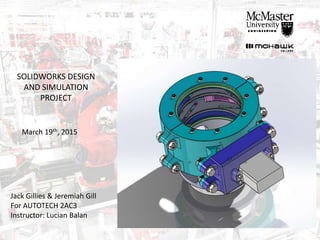
- 1. Jack Gillies & Jeremiah Gill For AUTOTECH 2AC3 Instructor: Lucian Balan SOLIDWORKS DESIGN AND SIMULATION PROJECT March 19th, 2015
- 2. Constraints: -Must be able to grip 3 prismatic shapes: -Must be controlled by given servo motor, 5 rotations to close/open -Must fit onto standard robot tool interface -All parts must be able to be manufactured -Assembly without interference -Must use standard fasteners -Robust and self-contained
- 3. Final Design
- 4. Final Design
- 5. Redesign - After we finished the modeling, we realized the gripper isn’t big enough to fit the cube - We measured the cube face to face and ignored the hypotenuse length of the cube - Redesign took about 10 hours – Would have been easier if we modeled more parametrically.
- 6. Final Design -522.19 grams -137 parts, 32 Unique parts -Can grip objects up to 80mm in width - 84.3 mm maximum height from arm interface - 194 mm maximum width (to back of servo)
- 7. Final Design
- 10. Inspiration -Camera Shutter closes equally around central point -Will make contact without lateral slip with any part. -Operates by turning overlapping “leaves” towards inside -Leaves are turned by pins which are driven by a central turning ring
- 11. Initial Design -5 Leaves overlapping (2mm thick) -Leaves Spaced by washers of same thickness -Assembly held in by retaining ring
- 13. Initial Design -5 Pins of varying length (increments of 2mm) to turn the leaves -Pins are pushed through slots in turning ring -Portion of bevel gear drives turning ring
- 14. Issues -Overlap of leaves may cause “tipping” or rocking of gripped piece -We decided to mirror whole assembly so 2 apertures grip piece at different heights
- 15. Retaining Case -Revolved profile of all turning parts to create casing to retain rotational motion -Mounting features for Motor assembly -Identical mounting brackets for M6 bolts -Upper holes machined for M4 screws to hold in upper leaf base. -This part will probably have to be casted in aluminum.
- 16. Drive Train -Total ratio needed is 39/1800 (turning ring degrees per motor degree) -Simple bevel gear and pinion would not be suitable -Additional gears achieve following ratio: 15 𝑃1 41 𝐺1 15 𝑃2 41 𝐺2 18 𝐵𝑃1 120 𝐵𝑃2 ≈ 39/1800 -Gearbox created to mount gears from motor to Retaining case
- 17. Drive Train
- 18. Turner Synchronization -Lower turning plate is driven by bevel gear -Upper turning plate is connected by turner synchros (shown in pink) -Assembly is held together with set screws -Plates slide inside grooves of retaining case
- 19. Spacer Cuff -This part spaces the whole assembly out from the arm interface -This allows the gripper to grip taller parts in closer to the center
- 20. Design Drawbacks -Weight -May shear objects -Large width – cannot fit into small spaces -Can only grip objects up to 80mm in diameter -Many parts only serviceable if completely disassembled -Leave assemblies are 54 mm apart – parts shorter than this will only be gripped by one leaf assembly.
- 21. Questions?