Downloaded 1,001 times

![Rapid Automation of every component is imperative!
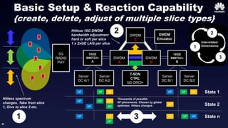
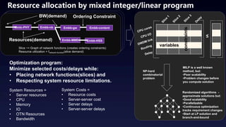
CAPEX savings of 5G cloud come from statistical gains.
• Want to allocate resources less than peak requirements.
• Statistical gains need fast adaption to take advantage of
ebb/flow of the tidal changes inter/intra slice.
• Slow reconfiguration means more equipment is required.
• Smaller Dt (i.e. better automation) reduced peak HW.
• Trade-offs of resources is complex optimization problem.
timeeMBB
IOT
Dt
Larger Dt =
More Peak HW
More Loss
X
X
timeeMBB
IOT
Dt
Smaller Dt =
Less Peak HW
Less Loss
OPEX of 5G nf()/ng() without automation greater than physical f()/g().
• Many more components to manage/configure than physical.
• Exploiting parallelism requires many more logical conns/nfs.
• Dynamic management of infrastructure not just RAT/RAN.
• Hand debugging of virtualized entities requires specialized skills.
f() g()
nfu[i]()
nfu[i]()
nfu[i]()
..
nfc[i]()
nfc[i]()
f()
ngu[i]()
ngu[i]()
ngu[i]()
..
ngc[i]()
ngc[i]()
g()
physical](https://image.slidesharecdn.com/end-to-endnetworkslicingashwoodsmith-161215094935/85/5G-End-to-end-network-slicing-Demo-11-320.jpg)
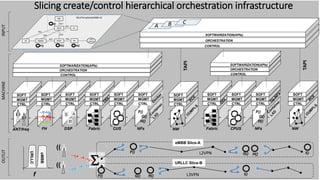
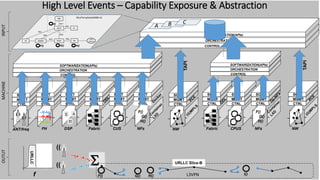
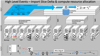
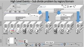
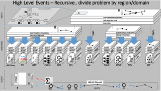
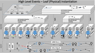
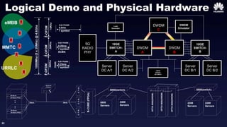
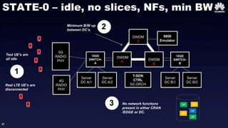
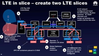
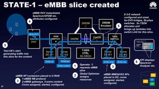
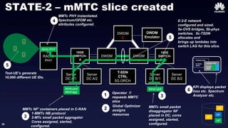
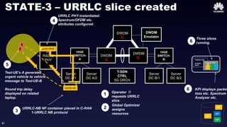
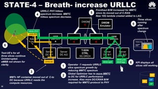
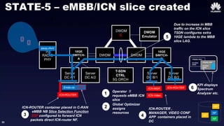
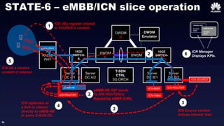
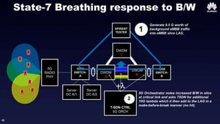


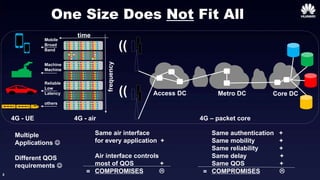
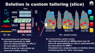
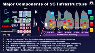
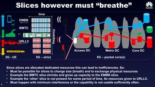
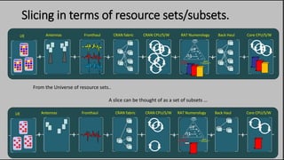
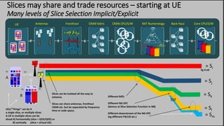
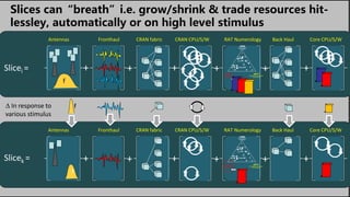
The document outlines a demonstration of 5G end-to-end slicing, emphasizing the need for flexible resource allocation tailored to different application requirements. It discusses various components of 5G infrastructure, including enhanced mobile broadband (eMBB), ultra-reliable low-latency communications (URLLC), and massive machine-type communications (mMTC), highlighting the importance of orchestration and software-defined networking (SDN). Efficient management of slices is crucial to prevent resource inefficiencies and ensure dynamic adaptability to changing demands.


