Annunciator for Hazard Prevention & Temperature Control

This document describes a microcontroller-based annunciator system that detects faulty conditions such as fires and informs operators through audible and visual alerts. The system uses various sensors to monitor conditions and provides the information to an AT89C51 microcontroller. If an abnormality is detected, the microcontroller alerts owners and initiates responses through a DTMF generator. It can also control devices like relays to regulate temperatures or turn on water pumps to extinguish fires. The system was tested experimentally and results were found to match computational analyses with less than 2% error, likely due to potentiometer loading effects. In conclusion, such automation improves safety and efficiency in industrial and other settings.

Recommended
Recommended
More Related Content
What's hot
What's hot (20)
Viewers also liked
Viewers also liked (20)
Similar to Annunciator for Hazard Prevention & Temperature Control
Similar to Annunciator for Hazard Prevention & Temperature Control (20)
More from IOSR Journals
Recently uploaded
Recently uploaded (20)
Annunciator for Hazard Prevention & Temperature Control
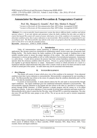
- 1. IOSR Journal of Electrical and Electronics Engineering (IOSR-JEEE) e-ISSN: 2278-1676,p-ISSN: 2320-3331, Volume 5, Issue 6 (May. - Jun. 2013), PP 45-48 www.iosrjournals.org www.iosrjournals.org 45 | Page Annunciator for Hazard Prevention & Temperature Control Prof. Ms. Manjeet G. Granthi1 , Prof. Mrs. Mohini S. Rajule2 1 Lecturer in Electronics & Telecommunication Dept. MIT College Aurangabad-431005 2 Lecturer in Electronics & Telecommunication Dept. MIT College Aurangabad-431005 Abstract: It is a microcontroller based annunciator system that detects different faulty condition and inform operator about it. It not only informs and announces about the faulty condition but also takes an initial to control the hazard.The system will consist of sensor which gives view of the condition to be monitored. If any abnormal condition arises then it gives indication to microcontroller. Microcontroller is programmed by user according to need. The Microcontroller may inform to the owner of a property about the condition abnormality and it set the driver on to take the remedial actions. Keywords - Annunciator, AT89C51, DTMF, EPROM I. Introduction Today all instrumentation system pertaining to industrial process control as well as domestic applications, like elevator control are centralized air conditioning control; involve some type of automatic fault finding facility. This facility detects the faulty condition of the operation towards it, enabling him to take suitable remedial action to ensure the proper operation of the system. One such method is annunciation. Annunciator is a device giving audible as well as visible indication of several physical parameters. Annunicator is a pilot device. A pilot device protects the process loop from serious hazardous condition by alerting the operator about the erroneous condition about the process. Process is a group of physical unit devices, which acts together to get desired objectives or output. Annunciator is device in which activation of a visual or a mechanical indicator called annunciator takes place when a remote switch or device has been activated as result of fault in certain part of the system. An audio alarm may also be associated with annunciator. II. SYSTEM DEVELIPMENT A. Block Diagram The system will consist of sensor which gives view of the condition to be monitored. If any abnormal condition arises then it gives indication to microcontroller. Microcontroller is programmed by user according to need. The Microcontroller may inform to the owner of a property about the condition abnormality and it set the driver on to take the remedial actions. It consists of microcontroller. A smoke detector detects the fire and sends to microcontroller through signal conditiones. The signal conditioner gives the conditioned information indicated to microcontroller. The microcontroller sends the indication to fire brigade and also inform to the other no. specified to it according to priority through DTMF Generator. A DTMF generator is already program with the contact no. to be dialed according to priority. It also gives indication to voice recorder for giving alarm indication and keeps record of it. Microcontroller drives relay to control the fire.The relay turns ON and OFF to control the temperature. The relay also turns ON and OFF,the water pumps to turn off fire. The set up can also be used to monitor temperature continuously. Fig1. Block Diagram The above figure is showing the block diagram of annunciator for hazard prevention and temperature control which consist of different blocks as Micro controller, DTMF Generator, RTC, Relay Driver, ADC, Voice recorder, Sensor and Signal conditioner.
- 2. Annunciator for Hazard Prevention & Temperature Control www.iosrjournals.org 46 | Page B. Micro Controller. The microcontroller used is 89C51. The microcontroller should have a capability to distinguish between the condition in normal and abnormal states. It also should take quick action after detection of danger. It should have real time so we used MCS 89C51. The features of 89C51 microcontroller are given below. Features : Compatible with MCS-51 products. 4K Bytes of In-System Reprogrammable Flash Memory Fully Static operation : 0 Hz to 24 MHz Three-level program Memory lock 128 x 8 bit Internal RAM 32 Programmable I/o Lines. Two 16 bit Timer/Counters Six Interrupt Sources Programmable Serial Channel The AT89C51 is a low power, high-performance CMOS 8-bit micro Computer with 4K bytes of Flash programmable and erasable read only memory (EPROM). The device is manufactured using Atmel's high density nonvolatile memory technology and is compatible with the industry-standard MCS-51 instruction set and pin out. The on-chip Flash allows the program memory to be reprogrammed in system or by a Conventional non volatile memory programmer. By combining a versatile 8 bit CPU with flash on a monolithic chip, the Atmel AT89C51 is a powerful microcomputer, which provides a highly flexible and cost-effective solution to many embedded control applications. II. PERFORMANCE ANALYSIS In the automated place, the system performance can be done by providing a direct software interface between the fire Alarm system and all other elements of the automation system. All large industries have annunciator panels for various alarms. Indeed some fire departments can display floor plans of building in the command center at a fire. It is logical next step to plug these displays into the alarm system to see the current status of place and then make a prediction of next five minutes. Performance analysis involves gathering formal and informal data to help customers and sponsors define and achieve their goals. Performance analysis uncovers several perspectives on a problem or opportunity, determining any and all drivers towards or barriers to successful performance, and proposing a solution system based on what is discovered. Performance analysis is the front end of the front end. It's what we do to figure out what to do. Some synonyms are planning, scoping, auditing, and diagnostics. A. System Testing System Testing is a critical element of measure of quality assurance and it represents the ultimate review of specifications and design. The system is tested during the above methods by verification of the results obtained by different methods. A number of both public-domain and commercial performance tools, explaining how each is used to collect and display performance data. While the tools exhibit important differences, there are also many similarities, and frequently our choice of tool will be driven more by availability than by the features provided. Paragraph is a portable trace analysis and visualization package developed at Oak Ridge National Laboratory for message-passing programs. It was originally developed to analyze traces generated by a message-passing library called the Portable Instrumented Communication Library (PICL) but can in principle be used to examine any trace that complies to its format. Like many message-passing systems, PICL can be instructed to generate execution traces automatically, without programmer intervention. Paragraph is an interactive tool. Having specified a trace file, the user instructs Paragraph to construct various displays concerning processor utilization, communication, and the like. The trace files consumed by Paragraph include, by default, time-stamped events for every communication operation performed by a parallel program. Paragraph performs on-the-fly data reduction to generate the required images. Users also can record events that log the start and end of user-defined ``tasks.'' Paragraph's processor utilization displays allow the user to distinguish time spent computing, communicating, and idling. Communication time represents time spent in system communication routines, while idle time represents time spent waiting for messages. These displays can be used to identify load imbalances and code components that suffer from excessive communication and idle time costs. which shows a Gantt chart (top part) and a space time diagram (bottom part) for a parallel climate model executing on 64 Intel DELTA processors. In the space-time diagram, the color of the lines representing communications indicates the size of the message being transferred. The climate model is a complex program with multiple phases. Initially, only processor 0 is active. Subsequently, the model alternates between
- 3. Annunciator for Hazard Prevention & Temperature Control www.iosrjournals.org 47 | Page computation and communication phases. Some of the communication phases involve substantial idle time, which should be the subject of further investigation. Communication displays can be used both to obtain more detailed information on communication volumes and communication patterns and to study causal relationships, The communication matrix on the left and the circle on the right both show instantaneous communication patterns. The colors in the communication matrix indicate communication volume, as defined by the scale above the matrix. Most matrix entries are on the diagonal, which indicates mostly nearest-neighbor communication. Another display in the top right presents cumulative data on processor utilization. A disadvantage of Paragraph is that the relationship between performance data and program source is not always clear. This problem can be overcome in part by explicitly logging events that record the start and end of ``tasks'' corresponding to different phases of a program's execution. Paragraph provides task Gantt and task histogram displays to examine this information. Of the portable tools described here, Paragraph is probably the simplest to install and use. Because it operates on automatically generated traces, it can be used with little programmer intervention. Paragraph displays are particularly intuitive, although the inability to scroll within display windows can be frustrating. Upshot is a trace analysis and visualization package developed at Argonne National Laboratory for message-passing programs. It can be used to analyze traces from a variety of message- passing systems: in particular, trace events can be generated automatically by using an instrumented version of MPI. Alternatively, the programmer can insert event logging calls manually. Upshot's display tools are designed for the visualization and analysis of state data derived from logged events. A state is defined by a starting and ending event. (For example, an instrumented collective communication routine can generate two separate events on each processor to indicate when the processor entered and exited the routine.) The Upshot Gantt chart display shows the state of each processor as a function of time. States can be nested, thereby allowing multiple levels of detail to be captured in a single display. States can be defined either in an input file or interactively during visualization. B. Calibration Table 1. Calibration of analog input voltage in accordance with temperature in degree centigrade. Reference voltage (mv) Temp in deg Celsius 10 1 20 2 50 5 100 10 200 20 300 30 400 40 500 50 C. Theoretical Computations: Vref-The reference voltage Vin – input voltage set to 5V Tout – output temperature Output temp. is given by Tout = (Vin X 2.56)/ Vref For e.g. Vin = 5V and Vref = 387mV, then Tout will be Tout =( 5 X 2.56)/387 Tout = 33o C Table 2 Comparison of Computational and experimental methods Computational output temp. (o C) Experimental output temp (o C) % Error 33 32.5 1.5 39 39.5 -1.5 54 53 1.85 58 57.9 0.17 72 71.6 0.5
- 4. Annunciator for Hazard Prevention & Temperature Control www.iosrjournals.org 48 | Page 80 80.1 0.12 90 89.8 1.66 102 102.7 0.29 107 106.5 0.37 123 123.1 0.48 131 130 0.76 Comparison of computational and experimental analysis -20 0 20 40 60 80 100 120 140 1 2 3 4 5 6 7 8 9 10 11 %Error Temp.indegcelsius Computational output temp. (oC) Experimental output temp (oC) % Error Fig.2 Comparison of Computational and Experimental Analysis D. Justification for error: The error introduced is due to loading effect of potentiometer used for temperature measurement. Since the system is a wide range system which is to be used for large varying temperatures and the voltages, therefore the care needs to be taken during the selection of the critical devices used , with regards to their operational ranges and the input provided in order to get the precise output with respect to the input. III. CONCLUSION In today's complex design needs and more efficient integration and reliability and lower cost devices. In the era of globalization and free economy everyday a new product is being launched in the market. Gone are the days when a particular brand was having monopoly in Indian markets. In the present scenario when competition is the keyword in the market, quality and minimum price is the mantra of success. The automation is playing a vital role in the global world keeping the human needs in focus. The life is becoming fully atomized and safety is given first priority with help of advance products and services of the same which are made available at your doorstep. The economy is also changed according to the human needs and therefore quality products and innovative products are also gearing their importance in changing technology everyday the world has come at our door with full information through internet engines. The idea has struck to mind that at various parts of industries, offices, banks, big malls, and educational institute etc, there is a big problem of the security and safety from the fire hazards which will destroy and damage the properties of the above mentioned organizations. This tends to think and use goods and products, which saves time and also save unnecessary cost. The designing of Annunciator for Hazard Prevention & Temperature Control has come to reality by developing the product through appropriate software and hardware. REFERENCES [1] Kenneth J Ayala, " The 8051 microcontroller" Architecture, programming & applications, 2nd Edition, penram international publishing (India). [2] Ajay V Deshmukh, " Microcontroller” Theory & applications, Tata Mc Graw Hill publishing company ltd., New Delhi. [3] Muhammad Ali Mazidi, Janice Gillispie Mazidi," The 8051 Microcontroller & Embedded Systems" Pearson Education. [4] AK Sawhney, " Electrical & Electronic measurements & instrumentation, 7th edition, Dhanpat Rai & Co. (p) Ltd., pp. 975-1000 [5] H.S.Kalsi, " Electronic instrumentation," Second edition, The Mcgraw- Hill Companies pp. 22-60, [6] http://www.google.com. [7] Manual of “Fire Alarm System”, by Photain Control System pp. 13-27 [8] Security Standard Technical Specification Manual pp. 110-128. http://www.allfirealarms.com.