![Research on the Control of Joint Robot Trajectory
www.ijres.org 39 | Page
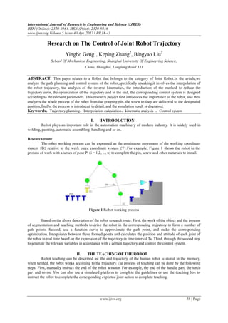
III. INTERPOLATION
3.1 Space interpolation
Introduce the linear interpolation after the introduction of circular interpolation.[2] Assume that the
coordinates at both ends of the straight line are P0 (X0, Y0, Z0) and Pe (Xe, Ye, Ze) and the robot's attitude. The
positional attitude of these important path points can be obtained by teaching methods. The length of the line is
L。
2
0e
2
0e
2
0e Z-ZY-YX-XL )()()( (1)
v is speed;Ts is Interpolation cycle; svTd 1 is Internal distance; a is Acceleration; 0v is Starting speed;
2
02
2
1
ss aTTvd is the distance within the interpolation cycle;
a
v
t 0
23t is acceleration and deceleration
time; 321 tttt is total time;
sT
t
N is the number of interpolation points;
Circular interpolation refers to the intersection of the arc plane and the three planes of the base coordinate
system. Take XOY plane arc as an example. Suppose P1, P2, P3 are not on the same line, as shown in Figure 2.
Figure 2 circular interpolation
V is linear velocity of the arc; t is interpolation interval. The same formula as the straight line is obtained:
i1i
ii1i
ii1i
sinYcosXY
sinY-cosXX
(2)
Figure 3 can help illustrate the process of turning a circular arc into a circular arc. It can have three
steps to illustrate: First, the three-dimensional graphics are mapped to two-dimensional plane. (Xi + 1, Yi + 1) is
obtained by using the above interpolation method in the two-dimensional plane. Finally, the coordinate values
are converted to the coordinates of the base coordinate system.
Figure 3 The relationship between the base coordinates and space Arc plane](data:image/gif;base64,R0lGODlhAQABAIAAAAAAAP///yH5BAEAAAAALAAAAAABAAEAAAIBRAA7)
Recommended
Recommended
More Related Content
What's hot
What's hot (17)
Similar to Research on The Control of Joint Robot Trajectory
Similar to Research on The Control of Joint Robot Trajectory (20)
More from IJRESJOURNAL
More from IJRESJOURNAL (20)
Recently uploaded
Recently uploaded (20)
Research on The Control of Joint Robot Trajectory
- 1. International Journal of Research in Engineering and Science (IJRES) ISSN (Online): 2320-9364, ISSN (Print): 2320-9356 www.ijres.org Volume 5 Issue 4 ǁ Apr. 2017 ǁ PP.38-43 www.ijres.org 38 | Page Research on The Control of Joint Robot Trajectory Yingbo Geng1 , Keping Zhang2 , Bingyao Liu2 School Of Mechanical Engineering, Shanghai University Of Engineering Science, China, Shanghai, Longteng Road 333 ABSTRACT: This paper relates to a Robot that belongs to the category of Joint Robot.In the article,we analyze the path planning and control system of the robot,specifically speaking,it involves the interpolation of the robot trajectory, the analysis of the inverse kinematics, the introduction of the method to reduce the trajectory error, the optimization of the trajectory and in the end, the corresponding control system is designed according to the relevant parameters. This research project first introduces the importance of the robot, and then analyzes the whole process of the robot from the grasping pin, the screw to they are delivered to the designated position,finally, the process is introduced in detail, and the simulation result is displayed. Keywords:Trajectory planning,Interpolation calculation,kinematic analysis ,Control system I. INTRODUCTION Robot plays an important role in the automation machinery of modern industry. It is widely used in welding, painting, automatic assembling, handling and so on. Research route The robot working process can be expressed as the continuous movement of the working coordinate system {B} relative to the work piece coordinate system {T}.For example, Figure 1 shows the robot in the process of work with a series of pose Pi (i = 1,2, ..., n) to complete the pin, screw and other materials to install. Figure 1 Robot working process Based on the above description of the robot research route: First, the work of the object and the process of segmentation and teaching methods to drive the robot in the corresponding trajectory to form a number of path points. Second, use a function curve to approximate the path point, and make the corresponding optimization. Interpolates between these formed points and calculates the position and attitude of each joint of the robot in real time based on the expression of the trajectory in time interval Ts. Third, through the second step to generate the relevant variables in accordance with a certain trajectory and control the control system. II. THE TEACHING OF THE ROBOT Robot teaching can be described as: the end trajectory of the human robot is stored in the memory, when needed, the robot works according to the trajectory.The process of teaching can be done by the following steps: First, manually instruct the end of the robot actuator. For example, the end of the handle part, the torch part and so on. You can also use a simulated platform to complete the guidelines or use the teaching box to instruct the robot to complete the corresponding expected joint action to complete teaching.
- 2. Research on the Control of Joint Robot Trajectory www.ijres.org 39 | Page III. INTERPOLATION 3.1 Space interpolation Introduce the linear interpolation after the introduction of circular interpolation.[2] Assume that the coordinates at both ends of the straight line are P0 (X0, Y0, Z0) and Pe (Xe, Ye, Ze) and the robot's attitude. The positional attitude of these important path points can be obtained by teaching methods. The length of the line is L。 2 0e 2 0e 2 0e Z-ZY-YX-XL )()()( (1) v is speed;Ts is Interpolation cycle; svTd 1 is Internal distance; a is Acceleration; 0v is Starting speed; 2 02 2 1 ss aTTvd is the distance within the interpolation cycle; a v t 0 23t is acceleration and deceleration time; 321 tttt is total time; sT t N is the number of interpolation points; Circular interpolation refers to the intersection of the arc plane and the three planes of the base coordinate system. Take XOY plane arc as an example. Suppose P1, P2, P3 are not on the same line, as shown in Figure 2. Figure 2 circular interpolation V is linear velocity of the arc; t is interpolation interval. The same formula as the straight line is obtained: i1i ii1i ii1i sinYcosXY sinY-cosXX (2) Figure 3 can help illustrate the process of turning a circular arc into a circular arc. It can have three steps to illustrate: First, the three-dimensional graphics are mapped to two-dimensional plane. (Xi + 1, Yi + 1) is obtained by using the above interpolation method in the two-dimensional plane. Finally, the coordinate values are converted to the coordinates of the base coordinate system. Figure 3 The relationship between the base coordinates and space Arc plane
- 3. Research on the Control of Joint Robot Trajectory www.ijres.org 40 | Page The following steps can complete the conversion from the coordinate obtained: first, the origin OR XRYRZR the original coordinate system into the coordinate origin O; second, rotational angle θ about the axis ZR, allowing X0 and XR parallel to each other; the first Third, around the XR axis rotation angle, get Z0 and ZR parallel to each other. In order to obtain the original coordinate system to ORXRYRZR coordinate system after the conversion of the coordinates, through the coordinate transformation after the inverse of the following conversion matrix 1 RT : 1000 )cosZscosYssin(X-cossincos-sinsin )sinZcoscosYcossin(X-sincoscoscossin- sinXcosX-0sincos T 1- R OROROR OROROR OROR inin ( (3) 11 1 1 1 1 1 1 1 z y x T w v u R 11 2 2 2 1 2 2 2 z y x T w v u R 11 3 3 3 1 3 3 3 z y x T w v u R (4) 3.2 joint space interpolation First of all to establish the corresponding constraints[1]. The initial angle of the angle function (t) of the joint at t0 = 0 is the angle of termination at tf. In practice, the starting and ending points satisfy the following constraints. ff 00 00 00 ff 00 t t t t t t )( )( )( )( )( )( (5) Combine Constraints and Five Interpolation Functions: 5 5 4 4 3 3 2 210)( tCtCtCtCtCCt (6) The coefficient of the interpolation function can be obtainedC0,C1,C2,C3,C4 and C5. The result of the obtained five interpolation function coefficients is: 5 2 000 5 4 2 000 4 3 2 000 3 0 2 01 00 2 )()66(1212 2 )23()1614(3030 2 )3()128(2020 2 f fffff f fffff f fffff t tt C t tt C t tt C C C C (7) According to the interpolation function θ (t) can be drawn as shown in Figure 5. The solid line represents the angle of change, the dotted line represents the varying angular velocity, and the fine red line indicates the angular acceleration.
- 4. Research on the Control of Joint Robot Trajectory www.ijres.org 41 | Page 0 0.5 1 1.5 2 2.5 3 3.5 4 -150 -100 -50 0 50 100 Time(s) Joint(deg) Figure 5 Articulated trajectories of five-order polynomial interpolation If there are multiple position gestures in the path planning of the robot, as in the figure below, there are C and D track points in addition to the A and B points. First, we use the inverse kinematics to find the variable values of each point in each joint. Secondly, we regard the corresponding joint variables of each end of the actuator as the interpolation point of the starting point and the end point. Figure 6 shows a smooth docking of each inserted point, you can link a motion curve into a robot. Figure 6 Robot job path point 3.3 Path optimization The end of the curve after interpolation is not smooth in a complete trajectory.[2] If the speed and acceleration function cannot be smooth enough to the robot parts will have a destructive impact. This is obviously unreasonable. In order to be able to solve this problem in a different position of the transition zone with a parabola to form a transition zone. The parabola can ensure that the acceleration of the period is constant, so that the speed of the starting point and the end point can be made smooth. This will cause the position and velocity of the entire spatial trajectory to be smoothly connected to one piece. As shown in Figure 6. Figure 7 Transition field trajectory t represents the parabolic delay time, the figure shows the same size of the acceleration at both ends and the symbols are different.This track is not difficult to see how many solutions. As shown in Figure 8. ht is the
- 5. Research on the Control of Joint Robot Trajectory www.ijres.org 42 | Page midpoint of time; h Position midpoint; hf t2t . The movement of the robot is smooth and continuous so that the following relationship is satisfied: h h - t t -t (8) 2 0 t 2 1 (9) 2 0f h )( (10) Can get: 0-tt-t 0ff 2 )( (11) 0 、 f 、 tf Is a known condition. The usual practice is to select the value of the acceleration, and then find the corresponding t : 2 -4-t - 2 t t 0f 2 f 2 f )( (12) From the above formula, we can get the corner of the constraints of the following conditions: 2 f 0f t -4 )( (13) If the above equal sign is established, there will be a little overlap. If the acceleration is too large will become no transition zone of the linear situation can not achieve the desired effect. Joint angle i , j and k Represents three adjacent path points. The linear function will connect to each of the two adjacent track points and use a parabolic transition. If the selected acceleration is appropriate, the actual path will become very desirable, as shown in Figure 9. Figure 8 Multi-segment linear trajectory with parabolic transition domain 3.4 Interpolation error reduction method In the process of control of the trajectory, each time the interpolation variable value (coordinate value) of a certain track point is obtained, the corresponding position is realized by enlarging the driving servo motor
- 6. Research on the Control of Joint Robot Trajectory www.ijres.org 43 | Page by the inverse motion to the angle value of each joint. The interpolated time interval is ts. Robot joint stiffness is relatively low so ask ts less than 25ms. The value of ts is not infinitely small and it is constrained by the amount of computation and the controller. Specifically, it is the calculation of positive and negative motion calculation and interpolation. Currently faster, the EtherCAT controller can achieve microseconds. Ts has its own lower limit. The ideal situation is equal to its lower limit of the value of this can get a higher precision and smooth trajectory. IV. CONTROL METHOD The working principle of the robot in the industrial field is the representation of the teaching process. Trajectories of regular paths, such as circles and straight lines,only need to describe the points of the corresponding trajectory[3].The main path points are calculated according to the inverse kinematics principle, the position and posture of the variable value are got as well, and then the control system describes the formation of this trajectory.Continuously repeating this process, the robot will complete a certain operation following the appropriate trajectory, the cause is shown in Figure 11. The track control system of the robot end is shown in Figure 9, it can be seen from the figure that the system’s accuracy is relatively high and the path is relatively smooth. Figure 9 Robot trajectory control process V. Result Description As shown in FIG. 10, the corresponding path points are given according the teaching point, through the interpolation calculation and the inverse kinematics transformation, interpolation curve is obtained, finally, a high-precision, continuous smooth trajectory curve is formed in terms of the method of parabolic curve optimization.This paper completes the study from the trajectory planning of the robot and the interchange of the parameters of the controller to the trajectory formed in this cause, in the end, the curve of the trajectory is shown in Fig.11. Figure 11 the trajectory after the controller is turned on REFERENCE [1]. Ren Chongxuan. Five-degree-of-freedom manipulator movement and control simulation analysis [D]. Guangzhou: South China University of Technology, 2012. [2]. Feng Jiang six degrees of freedom manipulator control system design and motion simulation [D] Beijing: Beijing University of Technology, 2012. [3]. TIAN Hai-bo, MA Hong-wei, WEI Juan.Study on Working Space and Structural Parameters of Series Robot Manipulator [J]. Journal of Agricultural Mechanization, 2013,44 (4): 196-201. [4]. Yu Bangyong, Mao Xianbiao. Robot work space analysis and simulation system [J]. Coal Mine Machinery, 2012,33 (8): 68-70.