
Recommended
More Related Content
Similar to sheet of pipe flow
Similar to sheet of pipe flow (20)
More from Dr. Ezzat Elsayed Gomaa
More from Dr. Ezzat Elsayed Gomaa (20)
Recently uploaded
Recently uploaded (20)
sheet of pipe flow
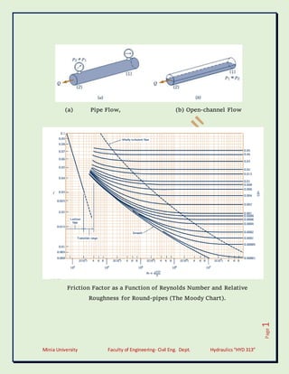
- 1. Minia University Faculty of Engineering- Civil Eng. Dept. Hydraulics“HYD 313” Page 1 (a) Pipe Flow, (b) Open-channel Flow Friction Factor as a Function of Reynolds Number and Relative Roughness for Round-pipes (The Moody Chart).
- 2. Minia University Faculty of Engineering- Civil Eng. Dept. Hydraulics“HYD 313” Page 2 Entrance Flow Conditions and Head Loss Coefficient: (a)Reentrance, K = 0.80, (b) Sharp-edged, K = 0.5, (c)Slightly Rounded, K = 0.2 (d) Well-rounded, K = 0.04. Exit Flow Conditions and Head Loss Coefficient: (a)Reentrance, K = 1.0, (b) Sharp-edged, K = 1.0,
- 3. Minia University Faculty of Engineering- Civil Eng. Dept. Hydraulics“HYD 313” Page 3 (d)Slightly Rounded, K = 1.0 (d) Well-rounded, K = 1.0. Minia University Faculty of Engineering Winter Semester: 2018- 2019 Sheet No. (1) 1. For fully developed viscous flow in a horizontal pipe, which of the following is true? a) Pressure forces are balanced by shear forces. b) Pressure forces result in fluid acceleration. c) Shear forces result in fluid deceleration. d) Pressure forces are balanced by body forces. 2. There is a steady laminar flow of water in a pipe of length. As the volume flowrate increases, the pressure drop over the length. a) Becomes larger. b) Becomes smaller. c) Stays the same. 3. Water flows steadily through a horizontal circular pipe. Which curve most correctly describes the pressure change through the pipe as the length is increased?
- 4. Minia University Faculty of Engineering- Civil Eng. Dept. Hydraulics“HYD 313” Page 4 4. Water flows steadily through a smooth pipe. For turbulent flow, if the velocity is increased, in general a) The friction factor increases. b) The friction factor decreases. c) The friction factor stays the same. 5. Water is pumped between two tanks as shown in the figure shown below. The energy line is as indicated. Is the fluid being pumped from A to B or from B to A? Explain. Which pipe has the larger diameter: A to the pump or B to the pump? Explain. 6. Two pipes of identical diameter and material are connected in parallel. The length of one of the pipes is twice the length of the other. The ratio of the flow rates in the two pipes is to be determined (f1 = 0.011 & f2 = 0.010).
- 5. Minia University Faculty of Engineering- Civil Eng. Dept. Hydraulics“HYD 313” Page 5 7. The pressure at section (2) shown in Fig. P8.73 is not to fall below 60 psi when the flowrate from the tank varies from 0 to 1.0 cfs and the branch line is shut off. Determine the minimum height, h, of the water tank under the assumption that minor losses are negligible. 8. When the pump shown in Fig. P8.92 adds 0.2 horsepower to the flowing water, the pressures indicated by the two gages are equal. Determine the flowrate. Length of pipe between gages 60 ft Pipe diameter 0.1 ft Pipe friction factor 0.03 Filter loss coefficient 12.
- 6. Minia University Faculty of Engineering- Civil Eng. Dept. Hydraulics“HYD 313” Page 6 9. The three water-filled tanks shown in above figure are connected by pipes as indicated. If minor losses are neglected, determine the flowrate in each pipe. 10. (45) (75) (64.5) L = 1200m, D = 200mm, f = 0.018 L =1800m, D = 200mm, f = 0.018 Calculate: The flow rate and the gage reading, neglecting local losses and velocity heads.
- 7. Minia University Faculty of Engineering- Civil Eng. Dept. Hydraulics“HYD 313” Page 7 “Remember” Define density or mass density, Specific Weight, Viscosity, Kinematic Viscosity Density of a fluid is defined as: the ratio of the mass of a fluid to its volume. Density, ρ = mass / volume (Kg/m3 ) ρwater = 1000 Kg/m3 Specific weight or weight density of a fluid is defined as: the ratio between the weights of a fluid to its volume. Specific weight, γ = weight/volume (N/m3 ) γ = ρ. g γwater = 9810 N/m 3 Viscosity is defined as the property of fluid which offers resistance to the movement of one layer of fluid over another adjacent layer of the fluid. ζ = μ (dV/ dy) μ – Dynamic viscosity or viscosity or coefficient of viscosity (N- s/m2 ) 1 N-s/m2 = 1 Pa.s = 10 Poise
- 8. Minia University Faculty of Engineering- Civil Eng. Dept. Hydraulics“HYD 313” Page 8 Kinematic viscosity: It is defined as the ratio between the dynamic viscosity and density of fluid. = μ / ρ (m2 /s) 1 m2 /s = 10000 Stokes (or) 1 stoke = 10-4 m2 /s Types of fluids Ideal fluid, Real fluid, Newtonian fluid, Non-Newtonian fluid, Ideal Plastic fluid. Define Compressibility Compressibility: is defined as the ratio of volumetric strain to compressive stress. Compressibility, β = (d Vol/ Vol) / dp (m2 /N) Define Surface Tension: Surface tension is defined as the tensile force acting on the surface of the liquid in contact with a gas or on the surface between two immiscible liquids such that the contact surface behaves like a membrane under tension. Surface Tension, σ = Force/Length (N/m) σwater = 0.0725 N/m σMercury = 0.52 N/m
- 9. Minia University Faculty of Engineering- Civil Eng. Dept. Hydraulics“HYD 313” Page 9 Surface tension on liquid droplet, σ = P.D/4 Surface tension on a hollow bubble, σ = P.D/8 Surface tension on a liquid jet, σ = P.D/2 σ – Surface tension (N/m) D – Diameter (m) P – Pressure inside (N/m2) Ptotal = Pinside + Patm Patm = 101.325 x 10³ N/m2 Define Capillarity Capillarity: is defined as a phenomenon of rise or fall of a liquid surface in a small tube relative to the adjacent general level of liquid when the tube is held vertically in the liquid. The rise of liquid surface is known as capillary rise while the fall of liquid surface is known as capillary depression. Capillary Rise or fall, h = (4σ cosθ) / ρg.D θ = 0 for glass tube and water, and θ = 130º for glass tube and mercury. Define Vapor Pressure Vapor Pressure: when vaporization takes place, the molecules start accumulating over the free liquid surface exerting pressure on
- 10. Minia University Faculty of Engineering- Civil Eng. Dept. Hydraulics“HYD 313” Page 10 the liquid surface. This pressure is known as Vapor pressure of the liquid. Define Control Volume Control Volume: A control volume may be defined as an identified volume fixed in space. The boundaries around the control volume are referred to as control surfaces. An open system is also referred to as a control volume. Write the continuity equation The equation based on the principle of conservation of mass is called continuity equation. δu/δx + δv/δy + δw/δz = 0 ----- three dimensional flow δu/δx + δv/δy = 0 ----- two dimensional flow Q = A1.V1 = A2.V2 ----- one dimensional flow List the types of fluid flow. Steady and unsteady flow Uniform and non-uniform flow Laminar and Turbulent flow Compressible and incompressible flow Rotational and ir-rotational flow
- 11. Minia University Faculty of Engineering- Civil Eng. Dept. Hydraulics“HYD 313” Page 11 One, Two and Three dimensional flow Define Steady and Unsteady flow Steady flow Fluid flow is said to be steady if at any point in the flowing fluid various characteristics such as velocity, density, pressure, etc. do not change with time. ∂V/∂t = 0, ∂P/∂t = 0, ∂ρ/∂t = 0 Unsteady flow Fluid flow is said to be unsteady if at any point flowing fluid any one or all characteristics which describe the behavior of the fluid in motion change with time. ∂V/∂t ≠ 0, ∂P/∂t ≠ 0, ∂ρ/∂t ≠ 0 Define Uniform and Non-uniform flow. Uniform flow: When the velocity of flow of fluid does not change both in direction and magnitude from point to point in the flowing fluid for any given instant of time, the flow is said to be uniform. ∂V/∂s = 0, ∂p/∂s = 0, ∂ρ/∂s = 0 Non-uniform flow: If the velocity of flow of fluid changes from point to point in the flowing fluid at any instant, the flow is said to be non-uniform flow. ∂V/∂s ≠ 0, ∂p/∂s ≠ 0, ∂ρ/∂s ≠ 0
- 12. Minia University Faculty of Engineering- Civil Eng. Dept. Hydraulics“HYD 313” Page 12 Compare Laminar and Turbulent flow: A flow is said to be laminar if Reynolds number is less than 2,400 for pipe flow. Laminar flow is possible only at low velocities and high viscous fluids. In laminar type of flow, fluid particles move in laminas or layers gliding smoothly over the adjacent layer. Turbulent flow: In Turbulent flow, the flow is possible at both velocities and low viscous fluid. The flow is said to be turbulent if Reynolds number is greater than 4000 for pipe flow. In Turbulent type of flow fluid, particles move in a zig – zag manner. Define Compressible and incompressible flow Compressible flow The compressible flow is that type of flow in which the density of the fluid changes from point to point i.e. the density is not constant for the fluid. It is expressed in kg/sec. ρ ≠ constant Incompressible flow The incompressible flow is that type of flow in which the density is constant for the fluid flow. Liquids are generally incompressible. It is expressed in m3 /s ρ = constant
- 13. Minia University Faculty of Engineering- Civil Eng. Dept. Hydraulics“HYD 313” Page 13 Define Rotational and Ir-rotational flow: Rotational flow Rotational flow is that type of flow in which the fluid particles while flowing along stream lines and also rotate about their own axis. Ir-rotational flow If the fluid particles are flowing along stream lines and do not rotate about their own axis that type of flow is called as ir- rotational flow Define One, Two and Three dimensional flow: One dimensional flow The flow parameter such as velocity is a function of time and one space coordinate only. u = f (x), v = 0 & w = 0. Two dimensional flow The velocity is a function of time and two rectangular space co- ordinates. u = f1(x,y), v = f2(x,y) & w =0. Three dimensional flow The velocity is a function of time and three mutually perpendicular directions. u = f1(x,y,z), v = f2(x,y,z) & w = f3(x,y,z). (x,y,z)
- 14. Minia University Faculty of Engineering- Civil Eng. Dept. Hydraulics“HYD 313” Page 14 Write the Bernoulli’s equation applied between two sections = pressure head = kinetic head Z = datum head. State the assumptions used in deriving Bernoulli’s equation Flow is steady; Flow is laminar; Flow is irrotational; Flow is incompressible; Fluid is ideal. Write the Bernoulli’s equation applied between two sections with losses. List the instruments works on the basis of Bernoulli’s equation: Venturi meter; Orifice meter; Pitot tube. Define Impulse Momentum Equation (or) Momentum Equation.
- 15. Minia University Faculty of Engineering- Civil Eng. Dept. Hydraulics“HYD 313” Page 15 The total force acting on fluid is equal to rate of change of momentum. According to Newton’s second law of motion, & Mention the range of Reynold’s number for laminar and turbulent flow in a pipe. If the Reynold’s number is less than 2000, the flow is laminar. But if the Reynolds’s number is greater than 4000, the flow is turbulent flow. What does Hagen - Poiseuille equation refer to? The equation refers to the value of loss of head in a pipe of length ‘L’ due to viscosity in a laminar flow. What is Hagen Poiseuille’s formula? (The expression is known as Hagen Poiseuille formula. Where = Loss of pressure head, V = Average velocity, µ = Coefficient of viscosity, and L = Length of pipe.
- 16. Minia University Faculty of Engineering- Civil Eng. Dept. Hydraulics“HYD 313” Page 16 What is meant by energy loss in a pipe? When the fluid flows through a pipe, it loses some energy or head due to frictional resistance and other reasons. It is called energy loss. The losses are classified as; Major losses and Minor losses Explain the major losses in a pipe: The major energy losses in a pipe is mainly due to the frictional resistance caused by the shear force between the fluid particles and boundary walls of the pipe and also due to viscosity of the fluid. Explain minor losses in a pipe: The loss of energy or head due to change of velocity of the flowing fluid in magnitude or direction is called minor losses. It includes: sudden expansion of the pipe, sudden contraction of the pipe, bend in a pipe, pipe fittings and obstruction in the pipe, etc. State Darcy-Weisbach equation OR What is the expression for head loss due to friction? Where: hL = Head loss due to friction (L), L = Length of the pipe (L), D = Diameter of the pipe (L), V = Velocity of flow (L/T)
- 17. Minia University Faculty of Engineering- Civil Eng. Dept. Hydraulics“HYD 313” Page 17 f = Coefficient of friction (---) What are the factors influencing the frictional loss in pipe flow? Frictional resistance for the turbulent flow is, i. Proportional to “V. n”, where V varies from 1.5 to 2.0. ii. Proportional to the density of fluid. iii. Proportional to the area of surface in contact. iv. Independent of pressure. v. Depend on the nature of the surface in contact. Write the expression for loss of head due to sudden enlargement of the pipe: Where, hexp. = Loss of head due to sudden enlargement of pipe. V1 = Velocity of flow at pipe 1; V2 = Velocity of flow at pipe 2. Write the expression for loss of head due to sudden contraction:
- 18. Minia University Faculty of Engineering- Civil Eng. Dept. Hydraulics“HYD 313” Page 18 hcon. = Loss of head due to sudden contraction, V = Velocity at outlet of pipe. Write the expression for loss of head at the entrance of the pipe: Where: hentr. = Loss of head at entrance of pipe. V = Velocity of liquid at inlet of the pipe. Write the expression for loss of head at exit of the pipe: Where: hexit. = Loss of head at exit of the pipe. V = Velocity of liquid at inlet and outlet of the pipe. What is compound pipe or pipes in series? When the pipes of different length and different diameters are connected end to end, then the pipes are called as compound pipes or pipes in series.
- 19. Minia University Faculty of Engineering- Civil Eng. Dept. Hydraulics“HYD 313” Page 19 What is mean by parallel pipe and write the governing equations? When the pipe divides into two or more branches and again join together downstream to form a single pipe then it is called as pipes in parallel. The governing equations are: and Define equivalent pipe and write the equation to obtain equivalent pipe diameter: The single pipe replacing the compound pipe with same diameter without change in discharge and head loss is known as equivalent pipe. What is meant by Moody’s chart and what are the uses of Moody’s chart? The basic chart plotted against Darcy-Weisbach friction factor against Reynold’s Number (Re) for the variety of relative roughness and flow regimes. The relative roughness is the ratio of the mean height of roughness of the pipe and its diameter (ε/D).
- 20. Minia University Faculty of Engineering- Civil Eng. Dept. Hydraulics“HYD 313” Page 20 Moody’s diagram is accurate to about 15% for design calculations and used for a large number of applications. It can be used for non- circular conduits and also for open channels. Define the terms: a) Hydraulic gradient line [HGL] b) Total Energy line [TEL] Hydraulic gradient line: It is defined as the line which gives the sum of pressure head and datum head of a flowing fluid in a pipe with respect the reference line. HGL = Sum of Pressure Head and Datum head Total energy line: Total energy line is defined as the line which gives the sum of pressure head, datum head and kinetic head of a flowing fluid in a pipe with respect to some reference line. TEL = Sum of Pressure Head, Datum head and Velocity head T.E.L = Sum H.G.L + Velocity head Write the dimensions for the followings.
- 21. Minia University Faculty of Engineering- Civil Eng. Dept. Hydraulics“HYD 313” Page 21 What are fluid machines or Hydraulic machines? The machines which use the liquid or gas for the transfer of energy from fluid to rotor or from rotor to fluid are known as fluid machines. How are fluid machines classified? Fluid machines are classified into two categories depending upon transfer of energy: Turbines – hydraulic energy is converted to mechanical energy and then electrical energy. Pumps – electrical energy is converted to mechanical energy and then hydraulic energy.
- 22. Minia University Faculty of Engineering- Civil Eng. Dept. Hydraulics“HYD 313” Page 22 What are called turbines? Hydraulic turbines are the machines which use the energy of water and convert it into mechanical energy. The mechanical energy developed by a turbine is used in running the electrical generator which is directly coupled to the shaft. A pipe network is represented in the following figure. All information is shown in the figure. With the data shown, determine the flowrate in each member of the system (Use Hardy Cross method).
- 23. Minia University Faculty of Engineering- Civil Eng. Dept. Hydraulics“HYD 313” Page 23
- 24. Minia University Faculty of Engineering- Civil Eng. Dept. Hydraulics“HYD 313” Page 24