2. 1. INTRODUCTION
The scanning tunneling microscope (STM) is a magnificent microscope ever built. It was generated in
1981 by Gerd Binning and Heinrich Rohrer of IBM’s Zurih Lab in Zurich,Switzerland. The invention
deserved Nobel prize for physics in 1986.
On October, 1986, the soccer team of IBM Zurich Laboratory
and Down Chemical played a game which had been arranged
earlier. To everyone’s surprise, a few hours before the game,
The Sweedish Academy announced the Nobel Prize for Gerd
Binning ( right ) and Heinrich Rohrer ( left ).
3. The Scanning Tunneling Microscope is an electron
microscope that transmit three-dimensional images of the
electron cloud around the nucleus.
The STM allows the inspection of the properties of a
conductive solid surface at an atomic size.
It is a very important technique in determining the atomic
structures and electronic states of the surface under
investigation.
Surfaces can be viewed at the atomic size thanks to the
high resolution (0.1 Ǻ) that STM has.
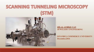
4. Basic components of STM
Five basic components:
1. Metal tip,
2. Piezoelectric scanner,
3. Current amplifier (nA),
4. Bipotentiostat (bias),
5. Feedback loop (current).
The scanner
can be
mounted with
the tip or the
sample stage.
5.
6. 2.TUNNELING EFFECT
The basis of STM is the quantum tunneling theory.
According to quantum tunneling theory, when the energy
of an electron exceeds its total energy, it can penetrate
regions which are impossible according to classical
physics. So it can tunnel.
In other words, if two conductors are brought closer to
each other by 10 Ǻ or more and a potential difference is
created between them, the electrons are likely to tunnel
through the potential barrier between these two
conductors.
7. 2.1.GENERATING TUNNELING CURRENT
A tunneling current occurs when electrons move through a barrier that they shouldn't be able to move
through in classic physics. In classical terms, if you don't have enough energy to move "over" a
barrier, you won't. However, in quantum mechanical world, electrons have wavelike properties. These
waves don’t end suddenly at a wall or barrier, but taper off quickly. If the barrier is thin enough, the
probability function can expand into the next region, through the barrier.
If a very sharp metal tip, called a probe (atomic size), is approached to the surface to be investigated
by a mechanical system (1-10 Ǻ) and a potential difference is applied, the wave functions of the type
and the surface superimpose and electrons are superimposed on the surface, A current is generated
called tunneling current.
A probe tip, usually made of W or Pt–Ir alloy. The tip is mechanically connected to the scanner, an
XYZ position device realized by means of piezoelectric materials. Distance between tip and surface
must be 1Å to 10Å.
8. 2.2. DIRECTION OF TUNNELING CURRENT
The direction of flow depends on the sign of the applied
potential.
If the sample is negatively charged, the electrons will pass
through the filled orbital of the sample to the empty orbital
of the tip.
The flow here is very small and at nA level.
9. 3.WORK PRINCIBLE OF STM
When voltage is generated between a specimen and a
tip with a very small distance (a few angstroms), due
to the quantum tunneling, there is an electron
transition from the specimen to tip or from tip to
specimen, which corresponds to a tunnel current at
the picoamper stage.
This tunneling current, which occurs when scanning
the specimen on the specimen surface, is measured
and is used to obtain surface tomography, since this
current is a function of the distance between the
specimen and the tip.
10. In constant-height mode, the tip scan in a horizontal plane above the
sample and the tunneling current varies depending on topography and
the local surface electronic properties of the sample. The tunneling
current measured at each location on the sample surface constitute the
data set, creating the topography image in figüre (a)
In the constant-current mode, by adjusting the height of the type, the
current is held constant by the feedback circuit which keeps the
current constant and is moved on the type surface. During this time,
changes are recorded in the height of the height of the image is
created. Showed as figüre (b)
11. 3.2. DISTANCE BETWEEN TIPAND SPECIMEN
The tunneling current varies exponentially depending on the distance
between the individual specimens.
It = Ve-kd
V: potential difference between conductors.
k: constant which depends on conductors composition
d: distance between the lowest (nearest to the sample) atom on the tip
and the highest (nearest) atom on the sample.
If the distance increases, the tunneling current (It) will decrease
exponentially.
12. 4. TIP PROPERTIES
The most important part of the scanning tunneling microscope is the tips.
The tunneling tip, provides the best images that are limited by a single metal
atom of the tip.
The traces were obtained by cutting the platinum / iridium wires or by
electrochemically etching the tungsten metal. At the present time,
electrochemical etching of Pt / Ir wires yields very clear solubility types
Close-up view of a Pt-Ir type
with a diameter of 0.25 mm
used in STM work.
13.
14. FACTORS EFECTING THE RESOLUTION
• One of the factors affecting resolution is corrugation, i.e. how much the electron density of surface
atoms varies in height above the surface.
• Graphite has a large corrugation, and is very planar, and thus is one of the easiest materials to image
with atomic resolution. (see next slide for example)
• STM does NOT probe the nuclear position directly, but rather it is a probe of the electron density, so
STM images do not always show the position of the atoms. STM imaging depends on the nature of the
surface and the magnitude and sign of the tunneling current. For example, if you have Cu and Si on the
same surface, under the same condition, the current with Cu is much higher .
15.
16. POSITIONING
The large distance range the tip has to be controlled on makes it necessary to use two positioners: a
coarse and a fine positioner.
The fine positioner is also used as a scanner. Every fine positioner/scanner is made out of a piezocrystal
or piezoceramic material.
17. 5. PIEZOELECTRIC EFECT
The piezoelectric effect was discovered by Pierre Curie in 1880. The effect is created by squeezing the
sides of certain crystals, such as quartz .The result creates of opposite charges on both sides. The effect can
be reversed as well; by applying a voltage across a piezoelectric crystal, it is going to be elongate or
compress.
The process is based on fundamental structure of a Crystal lattice crystals generally have a charge balance
where negative and positive charges precisely nullify eac other out along the rigid planes of the crystal
lattice. When this charge balance is disrupted by an external force, such as, applying physical stress to a
Crystal, the energy is transferred by electric charge carries, creating a surface charge density, which can be
collected via electrodes.
20. STM ADVANTAGES
STMs are helpful because they can give researchers a three dimensional profile of surface, which
allows researchers to analysis a multitude of characteristics, including roughness, surface defects and
determining things about the molecules size and conformation.
It is capable of capturing much more detail than other microscopes. This helps researchers better
understand the subject of their research on molecular level.
STMs are also versatile. They can be used for ultra high vacuum, air, water and other liquids and gasses.
They will activate in temperatures as low as zero Kelvin up to a few hundred degrees Celsius.
Scanning Tunneling Microscope works faster than Atomic Force Microscope.
AFM max sample size is 150x150 µm. On the other hand, STM generates mm size length and width.
Lastly, resolution of STM is much better than AFM.
21. STM DISADVANTAGES
There are very few disadvantages to using a scanning tunneling microscope.
STMs can be difficult to use effectively. There is very specific technique that requires a lot of
skill and precision.
STM requires very stable and smooth surfaces, excellent vibration control and sharp tips.
STMs use highly specialized equipment that is fragile and expensive.
Although, STM analysis only conductive materials, AFM uses for conductive and insulator
materials.
STM requires vacuum atmosphere but AFM can work even in liquid. For that reason AFM
can be used for biological materials.
22. REFERENCES
2. J. Chen, Introduction to Scanning Tunneling Microscopy, New York, Oxford
Univ. Press (1993).
Gan, Y., Chu, W., & Qiao, L. (2003). STM investigation on interaction between superstructure and grain
boundary in graphite. Surface Science, 539(1), 120-128.
Marti, O., & Amrein, M. (Eds.). (2012). STM and SFM in Biology. Academic Press..
Microscopy (pp. 59-67). Springer Netherlands.
http://jdetrick.blogspot.com.tr/2012/03/scanning-tunneling-microscope-and-3-d.html
http://www.nanoscience.com/technology/scanning-tunneling-microscopy/how-stm-works/