1. USE OF VFDS ON ASPHALT PLANT INDUCED DRAFT FANS
Glen R Anderson - Senior Energy Analyst - etc Group, Inc - Salt Lake City, UT
Patti L Case – Principal – etc Group, Inc – Salt Lake City, UT
Justin Lowery – Accounting/Utilities - Staker Parson Companies – Ogden, UT
ABSTRACT
Studies of 10 asphalt plants in the Intermountain
Region have identified average ID fan energy savings
of 68% by controlling airflow using Variable
Frequency Drives (VFDs) on the fan motors in place
of damper control (inlet or outlet). Average paybacks
were 3 -5 years before utility incentives.
In the 10 plants evaluated, the ID fans accounted
for as much as 30% of the total plant electrical
consumption. In the majority of these plants the
outlet dampers were typically 50%-60% closed. Fan
motors ranged from 200 Hp to 500 Hp.
With approximately 3,600 existing asphalt plants
in operation across the United States, a large
opportunity for retrofits exists. Working with
manufacturers and owners, a new standard can be
established for installing VFDs on all plants.
INTRODUCTION
As with many industrial processes,
manufacturers build asphalt plants designed to insure
equipment is sized to meet maximum production
needs under the worst operating conditions. This can
create the perfect storm when induced draft fans are
sized for an asphalt plant’s exhaust system.
Typically the exhaust system is sized for maximum
output, wet aggregate, and cold, humid air.
A huge opportunity exists to transfer standard
HVAC technologies to the industrial market. One
such opportunity is the use of VFDs on variable flow
fans in the asphalt industry. Plants typically operate
at less than 80% capacity under less demanding
weather conditions (dry aggregate, fairly dry and hot
air, and at less than full capacity.) Most asphalt
plants modulate airflow with an outlet damper to
meet exhaust requirements through the bag-house.
There are 3,600 hot mix asphalt plants in the
United States, producing almost 500 million tons of
asphalt paving material. About 1,300 of these plants
are of the drum mixing variety, as studied in this
paper (1).
Extrapolating savings achieved with 10 asphalt
plants in the Intermountain West, almost 200,000
MWh of annual energy savings could be achieved in
the United States through the installation of VFDs on
the induced draft fan motors.
ASPHALT PLANT OPERATION
Asphalt plants produce hot mix asphalt for
paving application. The paving aggregates are dried
and heated, then mixed and coated with asphalt
cement and briefly stored in heated silos. Trucks are
loaded from the silos and material is delivered to the
paving site. The hot mix is typically produced at
about 350°F and laid at 225°F or higher so it has a
fairly short “shelf life”.
Continuous mix asphalt plants operate by
feeding aggregate into a mixing drum where a burner
heats and dries the aggregate. Liquid asphalt cement
is added to the aggregate before the hot mix is
transferred from the drum to holding silos. Most
plants use some recycled pavement which is loaded,
screened and fed to the drum mixer.
Asphalt plant exhaust systems are designed to
use an induced draft fan to maintain a constant drum
vacuum pressure by drawing exhaust air from the
mixing drum through an air cleaner (baghouse or wet
scrubber). Standard design practice entails outlet
dampers on the fan to operate the plant at part flow
conditions.
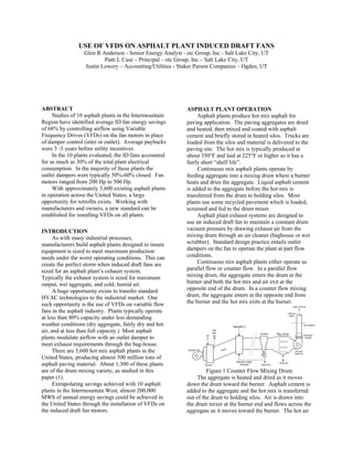
Continuous mix asphalt plants either operate as
parallel flow or counter flow. In a parallel flow
mixing drum, the aggregate enters the drum at the
burner and both the hot mix and air exit at the
opposite end of the drum. In a counter flow mixing
drum, the aggregate enters at the opposite end from
the burner and the hot mix exits at the burner.
Test Platform
Burner
Hot
Mix
out
Aggragate in
Recycle Larger
Particles Dust out
Cyclone
Clean Gas out
Exhaust
Stack
Bag House
Induced
Draft Fan
Drum
Discharge
Damper
Burner Fan
Air
in
Dust out
Figure 1 Counter Flow Mixing Drum
The aggregate is heated and dried as it moves
down the drum toward the burner. Asphalt cement is
added to the aggregate and the hot mix is transferred
out of the drum to holding silos. Air is drawn into
the drum mixer at the burner end and flows across the
aggregate as it moves toward the burner. The hot air
2. is exhausted from the mixer through a cyclone and
bag-house by an induced draft (ID) fan. There is a
discharge damper right at the fan exit.
The drum mixer typically operates around 325°F
and 0.25 inches negative water gauge pressure. The
burner is controlled by the drum bed temperature.
The ID fan discharge damper is controlled to
maintain the drum pressure. The picture below
shows an exhaust fan setup with an outlet damper.
Figure 2 Asphalt Plant Exhaust
PROJECT DEVELOPMENT
Utah Power FinAnswer Program
Utah Power operates an aggressive demand side
management program, called FinAnswer, that pays
up to 50% of the project cost based on 12¢ /kWh and
$50/average monthly kW for the first year of savings.
Utah Power hires consultants to identify and evaluate
energy saving opportunities for their customers.
Utah Power initiated a site visit with a consultant
(etc Group, Inc.) in December, 2002 at Staker Parson
Company’s (a wholly owned subsidiary of
OldCastle) Beck Street asphalt plant which identified
an opportunity for replacing the existing damper
control on the induced draft fan with a VFD. This
fan was powered by two 250 Hp motors.
Following the initial opportunity identification,
etc Group, Inc performed a detailed analysis (paid for
by Utah Power) to quantify the cost and savings
potential. Staker approved the project and completed
work in March 2003. Utah Power provided a
$22,540 incentive check to Staker in June, 2003 that
covered 50% of the project costs.
Measure Repeatability
The success of the first retrofit provided the
justification for Utah Power to fund studies at 4
additional Staker plants. Staker retrofit all of these
plants by the spring of 2004. OldCastle is
completing retrofits on 2 additional plants in Idaho
and is making preparations for the analysis of 3
plants in Spokane, Washington, while scoping
opportunities in Montana, Wyoming, Oregon, New
Mexico, Colorado, and South Dakota. They are
working with all of the local utilities to identify and
capture incentive opportunities.
Utah Power has transferred success with Staker’s
projects to other Utah Power served asphalt plant
operators. Two customers completed projects last
year with one possibly completing another retrofit
this winter and the other planning to analyze another
site this coming year.
METHODOLOGY
The energy savings estimates were based on
measured pre-retrofit baselines, production records
and fan system analysis. Actual savings were
verified with post retrofit fan power measurements.
Power was first logged on the fan motors for 2
to 3 weeks. Daily tons produced and logged fan
power was used to calculate hours of fan operation
and production rates. Normal annual production
(tons) and average production rates (ton/hr)
determine annual hours of operation. The logged
power data was extrapolated for a full year of
production by assuming the logged frequency
distribution remains constant throughout the year.
Figure 3 provides a histogram of the annual
distribution of fan energy.
-
100
200
300
400
500
600
50 100 140 150 160 170 180 190 200 210 220 230
kW
AnnualHours
Figure 3 Baseline Fan Energy
This data was used with flow measurements to
estimate the fan-flow load-duty cycle.
1. The fan motor energy was spot measured
simultaneously with airflow at multiple
operating points.
2. The measured data (corrected for
temperature and humidity) was used to
create a fan curve equation relating fan
power to flow.
3. This equation was used to calculate airflow
from the logged power.
Once the air-flow duty cycle was estimated, the
retrofit energy use for the variable speed fan was
calculated.
3. 4. One of the measurements in step 1 above
was made with the outlet damper wide open.
The airflow and power at this operating
point defines the system curve. According
to the fan affinity laws, the fan power
changes by the cube of the ratio change in
airflow.
kWnew = kWbase * (CFMnew/CFMbase) ^3.
5. The retrofit energy use is based on the fan
following the system curve to deliver the
same airflow distribution as in Step 3.
Figure 4 compares the measured power vs
airflow curve to the manufacturer provided curve.
0
50
100
150
200
250
300
0 20,000 40,000 60,000 80,000
ACFM
FanPower(Hp)
Measured
Fan Curve
Figure 4 Fan Curve - Published vs Measured
Figure 5 shows the curve fit equation used to
calculate airflow (CFM) based on the logged power.
y = 4.0525x1.7272
R2
= 0.9973
0
10,000
20,000
30,000
40,000
50,000
60,000
70,000
80,000
0 50 100 150 200 250 300
Fan Power
ACFM
225
Power (225)
Figure 5 Fan Curve Equation
Table 1 demonstrates the airflow and retrofit
energy calculations.
Hours CFM kW kWh
104 14,000 2 184
133 14,000 2 236
118 25,000 10 1,195
35 29,000 16 544
30 32,000 21 626
49 36,000 30 1,487
49 39,000 38 1,890
133 43,000 51 6,840
498 48,000 71 35,591
187 52,000 91 17,025
335 56,000 114 38,052
20 61,000 147 2,893
1,691 106,563
Table 1 Retrofit Fan Energy
RESULTS
Overview of All Plants
At 8 of the plants studied, the induced draft fans
initially accounted for 18% of the total plant energy.
Table 2 and Table 3 list energy characteristics of the
8 sites where pre and post measurements were taken.
Two of the plants analyzed only included post retrofit
measurements
Name Damper Plant kWh Fan kWh Fan %
Staker West Haven Outlet 1,021,040 304,681 30%
Ogden Plant Outlet 548,640 171,257 31%
POM Plant Outlet 1,284,480 318,618 25%
Orem Plant Inlet 890,250 96,731 11%
Staker Cedar City Outlet 502,320 115,949 23%
Staker Beck Street Outlet 2,374,500 471,804 20%
Staker Idaho Fed Way* Outlet 1,561,760 98,808 6%
Staker Idaho Ten Lane* Outlet 1,124,720 97,465 9%
9,307,710 1,675,313 18%
* Plant has electrically heated storage tanks
Table 2 Baseline Plant Energy Use
Verified savings range from 24% to 84% with
aggregated savings for all of the plants at 68%.
Name Pre-kWh Post-kWh % saved
Staker West Haven 304,681 108,227 64%
Ogden Plant 171,257 27,008 84%
POM Plant 318,618 87,706 72%
Orem Plant 96,731 33,726 65%
Staker Cedar City 115,949 42,586 63%
Staker Beck Street 471,804 106,157 77%
Staker Idaho Fed Way 98,808 52,456 47%
Staker Idaho Ten Lane 97,465 74,270 24%
1,675,313 532,136 68%
Table 3 Retrofit Fan Energy Use
Energy Use Details of a Single Plant
Eight of the fans have been re-measured after
VFD installation. The retrofit energy was within
15% of the predicted energy for all of the plants.
4. Figure 6 shows the energy use distribution for
the baseline, prediction, and actual retrofit
measurements for Staker’s Westhaven Asphalt plant.
-
100
200
300
400
500
600
700
800
900
50 100 140 150 160 170 180 190 200 210 220 230
kW
AnnualHours
Baseline Predicted Measured
Figure 6 Staker Ogden Results
Figure 7 shows the impact on monthly demand
following the installation of a VFD between 2003
and 2004.
0
100
200
300
400
500
600
700
800
Dec Nov Oct Sep Aug Jul Jun May Apr Mar Feb Jan
Demand(kW)
2003 2004
Figure 7 Staker Ogden Monthly kW
Project Financials
Several factors affect the payback of potential
projects. These include:
• Operating Hours
• Utility Rates
• Available Incentives
The projects analyzed in the Intermountain West
proved successful even with low operating hours
(typically around 1,200 hours annually) and low
utility rates (around 3¢/kWh). Utility incentives and
engineering expertise definitely pushed all of the
customers to complete projects. Asphalt plants
around the country will find attractive paybacks even
without incentives.
Table 4 shows the financials for the projects
analyzed.
Name Savings Cost Incentive Payback
Staker West Haven 15,025$ 31,997$ 15,999$ 1.1
Ogden Plant 17,865$ 62,531$ 20,288$ 2.4
POM Plant 10,509$ 45,211$ 22,606$ 2.2
Orem Plant 5,765$ 48,026$ 8,940$ 6.8
Staker Cedar City 7,785$ 16,338$ 8,169$ 1.0
Staker Beck Street 12,878$ 45,080$ 22,540$ 1.8
Staker Idaho Fed Way 3,565$ 28,766$ 5,246$ 6.6
Staker Idaho Ten Lane 4,598$ 22,749$ 7,427$ 3.3
77,990$ 300,698$ 111,215$ 2.4
Table 4 Project Financials
ADDITIONAL ITEMS OF CONSIDERATION
Inlet Vanes
Some manufacturers have followed the HVAC
industry by installing inlet vanes between the
baghouse and the exhaust fan. While the vanes do
provide savings as compared to outlet dampers, they
do not provide the same savings as HVAC inlet
vanes. Inlet vanes provide savings by creating a
swirl to the air as it enters the fan and correct
placement is important. The further the vanes are
from the inlet, the less benefit they provide. At the
plant studied, the inlet vane appears to be located too
far from the fan intake.
Figure 8 Fan With Inlet Damper
Figure 9 shows expected impact of the inlet
vanes as compared to an outlet damper, and to
variable speed control (VFD in this case).
Fan Power
0
50
100
150
200
250
300
0 10,000 20,000 30,000 40,000 50,000 60,000 70,000
ACFM
Hp
Inlet Vanes
Outlet Damper
VFD
Figure 9 Effect of Fan Control Mechanism
5. Burner Forced Draft Fans
All of the asphalt plants visited also operate with
forced draft fans on the burners. These fans present
additional savings opportunities, although the savings
potential is smaller and the costs will be greater.
Issues which have limited the use of variable speed
control on the burner FD fans include:
• Many of the plant manufacturers are
hesitant to use VFDs in burner controls.
The existing operation uses a common
linkage to control airflow and fuel flow
and they are concerned about breaking
this linkage. Existing plants whose
manufacturers will support VFDs
almost all need a control upgrade to
provide analog output signals to a VFD.
• As the fuel modulates from 0 to 50%,
the airflow varies from 0 to 100%. The
air flow stays at 100% above 50% load,
reducing the savings potential.
• The blower fan motors are only 30% to
50% the size of the exhaust fan motors.
CONCLUSION
Asphalt plant owners can benefit greatly by
installing VFDs on the induced draft fan motors of
the exhaust systems. Manufacturers typically size
fans to ensure proper operation under the most
extreme conditions. These conditions are seldom
realized so fans require damper control, wasting the
majority of the energy consumed by these fans.
VFDs have provided 68% savings of baseline
fan energy on 10 plants analyzed. 10 plants in the
Intermountain West are saving a combined
1,143,177 kWh. This measure can be duplicated in
the vast majority of the 1,300 drum mixing plants
nationwide.
REFERENCES
1. Baghouse Fines – Material Description, March 14,
2005, Recycled Materials Resource Center at the
University of New Hampshire.
http://www.rmrc.unh.edu/partners/userguide/bd.htm