Recommended

Recommended
More Related Content
What's hot
What's hot (18)
Similar to wireless ECG system based on android
Similar to wireless ECG system based on android (20)
Recently uploaded
Recently uploaded (20)
wireless ECG system based on android
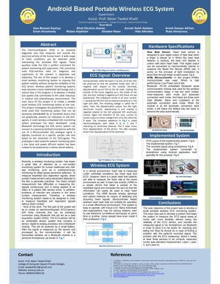
- 1. Android Based Portable Wireless ECG System Supervisors Assist. Prof. Abeer Twakol Khalil Computer Engineering Department - College of Computer_ Qassim Private Colleges Assist. Prof. Abeer Twakol Khalil College of Computer-Qassim Private Colleges Email: atwakol2013@ gmail.com Website: www.qc.edu.sa Phone: 00966567864136 Contact 1. S. F. Babiker, L. E. Abdel-Khair, and S. M. Elbasheer, "Microcontroller Based Heart Rate Monitor using Fingertip Sensors," UofKEJ Vol. 1 Issue 2 pp. 47-51, October 2011. 2. G. M. Friesen, T. C. Jannett, M. A. Jadalahh, S. L. Yates, S. R. Quint, and H. L. Nagle, “A Comparison of the Noise Sensitivity of Nine QRS Detection Algorithms,” IEEE Trans. Biomed. Eng., Vol. 37, No. 1, PP. 85-98, January 1990. 3. G. Diamond, and J. Wiley, "Electrocardiography and Vectrocardiography," 1975. 4. J. G. Webster, "Medical Instrumentation-Application and Design,". Boston: Houghton, 1978. 5. S.S. Taha, " Beginning of Android application and development" 6. S . S , Galal, "M.Gargenta, Learning Android“ the wrow programming, pp:1-29, 2011. 7. http://www.bluetooth.com/Bluetooth/Learn/Works/Data_Transport_Architecture.htm,2006. 8. http://www.bluetooth.com/Bluetooth/Learn/Works/Profiles_Overview.htm 9. https://www.android.com/ References The Electrocardiogram (ECG) is an essential diagnostic tool that measures and records the electrical activity of the human heart. A wide range of heart conditions can be detected when interpreting the recorded ECG signals. These qualities make the ECG a perfect instrument for patient monitoring and supervision. The commonly used ECG-machine used for diagnosis and supervision at the present is expensive and stationary. The aim of this project is to develop a small wireless monitoring system to improve the patient mobility without losing the reliability of the ECG sensor. Wireless patient monitoring systems have become a more established technology and a natural step in this progress is to develop a reliable ECG system that contributes to the cable reduction in medical and physiotherapy environments. The main focus of this project is to create a reliable small wireless ECG monitoring system at low cost. This project investigates the possibilities to create a small sized ECG monitoring system that can be wirelessly connected to a handheld device that can graphically presents an indication to the ECG- signals. A small wireless embedded ECG monitoring system prototype has been developed. Using Bluetooth technology the ECG sensor system can connect to a personal Android Smartphone with the use of a Microcontroller the analogue signal is digitally converted at a specific sample rate that based on the resolution of the ECG-signals. The prototype is well suited for patient monitoring were a low noise and power efficient system has been created to be powered by a cellular phone battery. Abstract In a clinical environment, heart rate is measured under controlled conditions like heart beat and ECG. However, there is a great need that patients are able to measure the heart rate in the home environment as well. A heart rate monitor (HRM) is a simple device that takes a sample of the heartbeat signal and computes the bpm so that the information can easily be used to track heart conditions. The HRM devices employ electrical and optical methods as means of detecting and acquiring heart signals. Microcontroller based wireless heart beat read out suitable for operation in a small office/home environment. This system is easy to operate, with Visual LCD. Many individuals and organizations may, for various reasons, wish to use electronic surveillance techniques at some time or another. Some people have even made it their profession; Fig.3. Introduction During diastole, while the heart is at rest, all of the cells are polarized so that the potential inside each cell is negative with respect to the outside. Normally, depolarization occurs first at the SA node, making the outside of the tissue negative w.r.t. the inside of the cell, and also, making it negative w.r.t the tissue not yet depolarized. This imbalance results in an ionic current, I, causing the left arm (LA) to measure positive w.r.t. the right arm (RA). The resulting voltage is called the P wave. Then, the depolarization passes into the right ventricular muscle, depolarizing it and making it negative relative to the still polarized left ventricular muscle. Again the direction of the ionic current (I) causes a plus-to-minus voltage from LA to RA called the R wave. The complete waveform in Fig.2 is called electrocardiogram, with labels P, Q, R, S, and T indicating its distinctive features. The P wave arises from depolarization of the atrium. The QRS complex arises from depolarization of the ventricles. ECG Signal: Overview - Hear Beat Sensor: Heart beat sensor is designed to give digital output of heat beat when a finger is placed on it. When the heart beat detector is working, the beat LED flashes in unison with each heart beat. This digital output can be connected to microcontroller directly to measure the Beats Per Minute (BPM) rate. It works on the principle of light modulation by blood flow through finger at each pulse, Fig.4. - ATML Microcontroller: In this project ATMEL microcontroller was used. Which is high performance, Low Power and 8-bits. - Bluetooth: HC-05 embedded Bluetooth serial communication module was used for the wireless communication stage, it has two work modes: order-response work mode and automatic connection work mode. And there are three work roles (Master, Slave and Loopback) at the automatic connection work mode. When the module is at the automatic connection work mode, it will follow the default way set lastly to transmit the data automatically. Hardware Specifications The main objective of this project was to develop a small portable wireless ECG monitoring system. The basic idea was to develop a system that helps the patient to measure the ECG signal easily at home with more flexibility without losing the reliability of the ECG sensor, and transfer the measured signal to his Smartphone via Bluetooth in order to send it to his doctor for checking and telling him what he should do in case of finding a problem with the patient's recorded signal. The problem with the ECG measuring; where it needs at least three sensors to be correctly measured (under lead standard measurement: Lead-I; Lead- II, and Lead-III). Conclusions Recently, a wireless monitoring system, has drawn a great deal of attention as a non-contact monitoring system for human healthcare and vital- sign monitoring, such as in cardiopulmonary monitoring for sleep apnea syndrome detection. To measure heartbeat and respiration signals, direct contact measurement using electrodes attached to the skin is generally practiced. The direct contact measurement has difficulties in measuring bio- signals continuously and in being applied to an infant or a patient with severe burns. In addition, problems of infection are inherent in the direct contact measurement. Therefore, a wireless monitoring system needs to be designed in order to measure heartbeat and respiration signals without direct contact. - Aims of the work: The first part of the project will be to create an electrocardiograph (ECG-sensor) with three channels that can be wirelessly connected using Bluetooth that will act as a data acquisition system (DAQ). The ECG-sensor will be an embedded sensor system that contains a sensor, digital-to-analog processor and a Bluetooth module. This will be powered by a small battery. After the signal is measured by the sensor and processed by the microcontroller; it will be transmitted wireless via a Bluetooth module to a personal Smartphone, as shown in Fig.1. Wireless ECG System Fig. 1 A block diagram for wireless monitoring system Fig.2 ECG definitions (Typical ECG Beat). Fig.3 Wireless ECG Mentoring System Fig.4 Heart Beat Sensor Fig.5 HC-05 Bluetooth Implemented System - PCB Layout of the implemented system; Fig.6. - The implemented system; Fig.7. - The recorded signal using smartphone; Fig.8. - The implemented system connected to smartphone using Android application built specially for this purpose; Fig.9. Fig.6 PCB of the System Fig.7 View of the System Fig.9 Testing the System Fig.8 Recorded Signal Team Work Alaa Mosaad Alyahya Afrah Ebrahim Alamer. Amnah Saleh Alzaben Aroob Hassan Alfrhan Eman Alrasheedy Wijdan Alqahtani Ghadeer Naser Hala Alkredes Ruba Almazroua.