![1615
switch and negative and gate. The schematic is as follows:
Figure 2 Lead switchover circuit
There are A, B, C and D four lead switchover controlling
ends. They are connected with the I/O pins of the MCU.
The amplitude of the electrocardiosignal is between 1mV
and 5mV. It is too low for the I/O pins of the MCU. So before
transporting the electrocardiosignal to the MCU it must be
enlarged. Generally, the withstand voltage of the MCU’s I/O
pins is between 3V and 5V. So the magnification times of the
electrocardiosignal is between 500 and 1000. The
magnification times is designed 1000 in this monitor. The
amplifying circuit is divided to the head amplifier and the post
amplifier. The magnification times of the head amplifier is 20
and the post amplifier’s is 50. And the filter circuit is between
the head amplifier and the post amplifier.
In order to collecting exact electrocardiosignal, we must
know about the electrocardiosignal and its undesired signal.
The main frequency of the human body’s electrocardiosignal
is between 0.05Hz and 100Hz. And the most common
undesired signal of the electrocardiosignal are the power
frequency interference (generally 50Hz) and the
myoelectricity frequency interference (its frequency is about
35Hz). So the band-pass filter consists of the RC high pass
filter (its cut-off frequency is 0.05Hz) and the RC low pass
filter (its cut-off frequency is 100Hz). And in order to
eliminating the interference between the high pass filter and
the low pass filter, an operational amplifier is put between
them. On the other hand, in order to eliminating the power
frequency interference and the myoelectricity frequency
interference, a 35Hz Double T-notch filter and a 50Hz Double
T-notch filter are designed in the circuit[1]
.
2.2 The Single Chip Microcomputer controlling core
In this monitor, the Microprocessor C8051F021 is chose
to be the controlling core of the system. The C8051F021 has a
lot of functional module, such as: the GPIO, the timer, the
external interrupt the 12-bit analog-to-digital converter and so
on. In addition, the 32 I/O pins of the C8051F021 are
adequate to the control switch and the control output.
2.3 The USB Host Interface
In this part, SL811HS is chose to be the USB host
interface chip. The SL811HS is an embedded USB Host/Slave
controller capable of communicating in either full-speed or
low-speed. SL811HS has 8-bit bidirectional data port I/O,
on-chip SIE, on-chip USB transceivers, and 256-byte internal
SRAM buffer. It supports suspend/resume, wake up and
low-power modes. So the SL811HS is quite suitable for being
the USB Host Interface chip. The surrounding connection of
the LS811HS is as follows:
Figure 3 Surrounding connection of the SL811HS
The SL811HS connects the MCU by D0-D7, nCS, nWR,
nRD, A0, INTRQ, nRST. The D0-D7 is the 8-bit bidirectional
data port I/O. They are in charge of transporting data between
the SL811HS and the MCU. The nCS can enable the
SL811HS when a low electric level on it. The nWR and nRD
are the Write and Read enabling end. The INTRQ can send the
Interrupt Request to the MCU. And the nRST is the restart
signal receiving end.
3. SOFTWARE DESIGN
The software system of the portable ECG monitor
includes: the program of analog-to-digital conversion, the
implementation of USB Host Specification framework, the
Authorized licensed use limited to: Khwaja Fareed University of Eng & IT. Downloaded on September 28,2021 at 14:48:54 UTC from IEEE Xplore. Restrictions apply.](data:image/gif;base64,R0lGODlhAQABAIAAAAAAAP///yH5BAEAAAAALAAAAAABAAEAAAIBRAA7)
Recommended
Recommended
More Related Content
What's hot
What's hot (17)
Similar to The research of_portable_ecg_monitoring_system_with_usb_host_interface
Similar to The research of_portable_ecg_monitoring_system_with_usb_host_interface (20)
More from ArhamSheikh1
More from ArhamSheikh1 (7)
Recently uploaded
Recently uploaded (20)
The research of_portable_ecg_monitoring_system_with_usb_host_interface
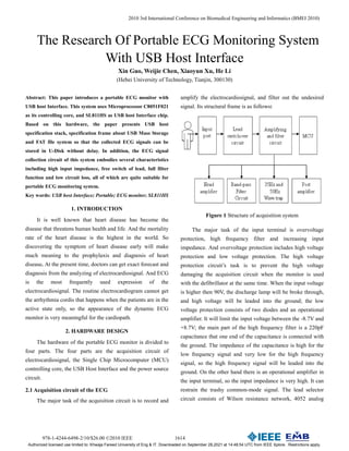
- 1. 978-1-4244-6498-2/10/$26.00 ©2010 IEEE 1614 2010 3rd International Conference on Biomedical Engineering and Informatics (BMEI 2010) The Research Of Portable ECG Monitoring System With USB Host Interface Xin Guo, Weijie Chen, Xiaoyun Xu, He Li (Hebei University of Technology, Tianjin, 300130) Abstract: This paper introduces a portable ECG monitor with USB host Interface. This system uses Microprocessor C8051F021 as its controlling core, and SL811HS as USB host Interface chip. Based on this hardware, the paper presents USB host specification stack, specification frame about USB Mass Storage and FAT file system so that the collected ECG signals can be stored in U-Disk without delay. In addition, the ECG signal collection circuit of this system embodies several characteristics including high input impedance, free switch of lead, full filter function and low circuit loss, all of which are quite suitable for portable ECG monitoring system. Key words: USB host Interface; Portable; ECG monitor; SL811HS 1. INTRODUCTION It is well known that heart disease has become the disease that threatens human health and life. And the mortality rate of the heart disease is the highest in the world. So discovering the symptom of heart disease early will make much meaning to the prophylaxis and diagnosis of heart disease. At the present time, doctors can get exact forecast and diagnosis from the analyzing of electrocardiosignal. And ECG is the most frequently used expression of the electrocardiosignal. The routine electrocardiogram cannot get the arrhythmia cordis that happens when the patients are in the active state only, so the appearance of the dynamic ECG monitor is very meaningful for the cardiopath. 2. HARDWARE DESIGN The hardware of the portable ECG monitor is divided to four parts. The four parts are the acquisition circuit of electrocardiosignal, the Single Chip Microcomputer (MCU) controlling core, the USB Host Interface and the power source circuit. 2.1 Acquisition circuit of the ECG The major task of the acquisition circuit is to record and amplify the electrocardiosignal, and filter out the undesired signal. Its structural frame is as follows: Figure 1 Structure of acquisition system The major task of the input terminal is overvoltage protection, high frequency filter and increasing input impedance. And overvoltage protection includes high voltage protection and low voltage protection. The high voltage protection circuit’s task is to prevent the high voltage damaging the acquisition circuit when the monitor is used with the defibrillator at the same time. When the input voltage is higher then 90V, the discharge lamp will be broke through, and high voltage will be leaded into the ground; the low voltage protection consists of two diodes and an operational amplifier. It will limit the input voltage between the -8.7V and +8.7V; the main part of the high frequency filter is a 220pF capacitance that one end of the capacitance is connected with the ground. The impedance of the capacitance is high for the low frequency signal and very low for the high frequency signal, so the high frequency signal will be leaded into the ground. On the other hand there is an operational amplifier in the input terminal, so the input impedance is very high. It can restrain the trashy common-mode signal. The lead selector circuit consists of Wilson resistance network, 4052 analog Authorized licensed use limited to: Khwaja Fareed University of Eng & IT. Downloaded on September 28,2021 at 14:48:54 UTC from IEEE Xplore. Restrictions apply.
- 2. 1615 switch and negative and gate. The schematic is as follows: Figure 2 Lead switchover circuit There are A, B, C and D four lead switchover controlling ends. They are connected with the I/O pins of the MCU. The amplitude of the electrocardiosignal is between 1mV and 5mV. It is too low for the I/O pins of the MCU. So before transporting the electrocardiosignal to the MCU it must be enlarged. Generally, the withstand voltage of the MCU’s I/O pins is between 3V and 5V. So the magnification times of the electrocardiosignal is between 500 and 1000. The magnification times is designed 1000 in this monitor. The amplifying circuit is divided to the head amplifier and the post amplifier. The magnification times of the head amplifier is 20 and the post amplifier’s is 50. And the filter circuit is between the head amplifier and the post amplifier. In order to collecting exact electrocardiosignal, we must know about the electrocardiosignal and its undesired signal. The main frequency of the human body’s electrocardiosignal is between 0.05Hz and 100Hz. And the most common undesired signal of the electrocardiosignal are the power frequency interference (generally 50Hz) and the myoelectricity frequency interference (its frequency is about 35Hz). So the band-pass filter consists of the RC high pass filter (its cut-off frequency is 0.05Hz) and the RC low pass filter (its cut-off frequency is 100Hz). And in order to eliminating the interference between the high pass filter and the low pass filter, an operational amplifier is put between them. On the other hand, in order to eliminating the power frequency interference and the myoelectricity frequency interference, a 35Hz Double T-notch filter and a 50Hz Double T-notch filter are designed in the circuit[1] . 2.2 The Single Chip Microcomputer controlling core In this monitor, the Microprocessor C8051F021 is chose to be the controlling core of the system. The C8051F021 has a lot of functional module, such as: the GPIO, the timer, the external interrupt the 12-bit analog-to-digital converter and so on. In addition, the 32 I/O pins of the C8051F021 are adequate to the control switch and the control output. 2.3 The USB Host Interface In this part, SL811HS is chose to be the USB host interface chip. The SL811HS is an embedded USB Host/Slave controller capable of communicating in either full-speed or low-speed. SL811HS has 8-bit bidirectional data port I/O, on-chip SIE, on-chip USB transceivers, and 256-byte internal SRAM buffer. It supports suspend/resume, wake up and low-power modes. So the SL811HS is quite suitable for being the USB Host Interface chip. The surrounding connection of the LS811HS is as follows: Figure 3 Surrounding connection of the SL811HS The SL811HS connects the MCU by D0-D7, nCS, nWR, nRD, A0, INTRQ, nRST. The D0-D7 is the 8-bit bidirectional data port I/O. They are in charge of transporting data between the SL811HS and the MCU. The nCS can enable the SL811HS when a low electric level on it. The nWR and nRD are the Write and Read enabling end. The INTRQ can send the Interrupt Request to the MCU. And the nRST is the restart signal receiving end. 3. SOFTWARE DESIGN The software system of the portable ECG monitor includes: the program of analog-to-digital conversion, the implementation of USB Host Specification framework, the Authorized licensed use limited to: Khwaja Fareed University of Eng & IT. Downloaded on September 28,2021 at 14:48:54 UTC from IEEE Xplore. Restrictions apply.
- 3. 1616 implementation of USB Mass Storage framework, the implementation of FAT file system. The USB Host Specification framework consists of four layers. The first layer is the achievement of the communication between the C8051F021 and the SL811HS. The second layer is the achievement of the data packet between the USB Host and the USB Slave. The third layer is the achievement of the USB Specification standard request. The fourth layer is the achievement of the USB Host Flow. The higher the layer is, the more advanced it is. The lowest layer and the hardware are interrelated closely. The higher the layer is, the less relation between the layer and the hardware is. And the highest layer has nothing with the hardware. So it is quite suitable for transplanting. The USB Mass Storage framework is used to achieving the disk management and the transmission of mass data. This framework bases on 19 UFI commands. The commands include Format Unit, Inquiry, Mode Select, Verify and so on. If the 19 commands are achieved, the USB Mass Storage framework is achieved. The FAT file system connects the U-Disk by the achievement of 19 UFI commands[2] . And the FAT file system will establish a struct of the U-Disk in the USB Host. The struct is used to create, search, write, read and delete the files. The relationship of these modules is as follows: Figure 4 Structure of USB Host software system 3.1 The configuration of the U-Disk After the initialization of the MCU and the restoration of the USB serial bus, the main circle program will enable the interrupt of the device detection. Then the monitor will wait the U-Disk insert. When the U-Disk connects with the monitor, the SL811HS will send the interrupt request to the MCU[3] . Then the MCU will get the type of the interrupt by reading the interrupt state register. When the type of the interrupt indicates that there is a U-Disk connects with the monitor, the MCU will configure the U-Disk. Before the U-Disk is configured, its default addresses and default communications pipe are both 0. The steps that configure the U-Disk are as follows[4] : (1) The USB Host sends the Get-Descriptor command to the U-Disk. Then a few Device Descriptor of the USB Slave will be sent back. (2) The USB Host sends the Set-Address command to the U-Disk. This command will set the new address of the U-Disk. (3) The USB Host sends the Get-Descriptor command again. At this time, all of the Device Descriptor of the USB Slave will be sent back. (4) The USB Host sends the Get-Configuration command to the U-Disk. The USB Slave will send the Configuration Descriptor, the Interface Descriptors and the endpoint Descriptors back. (5) The USB Host sends the Set-Configuration command to the U-Disk for configuring it. After the U-Disk is configured, the U-Disk will use the new address for the communication between the USB Host and the U-Disk. 3.2 The identification of the file system of the U-Disk At the present time, a majority of the U-Disk’s file system is the FAT file system. And the FAT file system includes the FAT16 file system and the FAT32 file system. So it is necessary to distinguish which file system of the U-Disk uses. The result of the identification will be stored in a variable. When the value of the variable is ‘1’, the file system of the U-Disk is the FAT32 file system. When the value of the variable is’0’, the file system of the U-Disk is the FAT16 file system. The theory of the FAT32 file system and the FAT16 file system are nearly. Here we take the FAT32 file system for example. Program of the main circle Interrupt service routine FAT file system USB Mass Storage framework Firmware of the SL811HS Writ and read program of the SL811HS Hardware of the SL811HS Authorized licensed use limited to: Khwaja Fareed University of Eng & IT. Downloaded on September 28,2021 at 14:48:54 UTC from IEEE Xplore. Restrictions apply.
- 4. 1617 The FAT32 file system is divided to five parts. They are the MBR, the DBR, the FAT, the FDT and the DATA. The relative position of the five parts is as follows: Figure 5 Organizational structure of the FAT32 3.3 The operation of the files in the U-Disk The operation of the files in the U-Disk is as follows: (1) Create Directory, the function prototype is: unsigned char CreateDir (unsigned long len, unsigned char *pBuffer, unsigned char *pName). The input parameters are the length of the long file name, the pointer points to the directory entry of the short file name and the pointer points to the directory entry of the long file name. (2) Create a file under the present directory, the function prototype is: unsigned char CreateFile (unsigned long len, unsigned char *pBuffer, unsigned char *pName). The input parameters are same with the Create Directory. (3) Set the pointer of the files, the function prototype is; unsigned char SetFilePointer (unsigned long pointer). The input parameter is the pointer points to the file. (4) Open a file, the function prototype is: unsigned char OpenFile (unsigned char *pBuffer). The input parameter is the file name. (5) Write data into a file, the function prototype is: unsigned char WriteFile (unsigned long writeLength, unsigned char *pBuffer). The input parameters are the length of the data and the pointer points to the data. 3.4 The data transmission between the monitor and the U-Disk The data transmission between the monitor and the U-Disk is based on the Bulk endpoints. The Bulk transmission is divided to Bulk-In and Bulk-Out[5] . The process that the monitor writes data into the U-Disk is the Bulk-Out. Generally a sector consists of 512 bytes in the U-Disk. But the maximum bytes in a Bulk-Out packet are 64. So it needs 8 circles for writing a sector in the U-Disk. The transmission process of the Bulk-Out is illustrated in Figure 6 [6] . Figure 6 Process of Bulk-Out transmission MBR 62 reserved sectors DBR 31 reserved sectors FAT1 FAT2 Root Folder DATA Remain sectors Start Send CBW to Bulk-Out ACK? Send PID-OUT to Bulk-Out ACK? Send data to Bulk-Out Transmission over? Send PID-IN to Bulk-In ACK? Receive CSW Transmission over? End Error Processing N Y Y Y Y Y N N N N Authorized licensed use limited to: Khwaja Fareed University of Eng & IT. Downloaded on September 28,2021 at 14:48:54 UTC from IEEE Xplore. Restrictions apply.
- 5. 1618 4. CONCLUSION The portable ECG monitor introduced in this paper is designed for that the cardiopath can monitor their heart condition in their daily life. This monitor is easy to use and carry, small, low energy consumption and running stably. So it is very suitable for the 24-hour monitoring. Moreover a USB Host Interface is designed for the portable ECG monitor. This is the main innovation in this paper. So we can use the U-Disk in stead of the internal storage of the monitor. It makes the circuit of the monitor simpler, and cut down the development cycle. In addition, the main purpose of designing the USB Host Interface in a portable ECG monitor is as below. With the rapid development and spread of the USB interface technology, there will more functional module with USB Interface come about. These modules can display, analyze, transfer the electrocardiosignal date, control and drive the treatment equipment automatically. So the monitor can connect with the relevant module in times of need. REFERENCES [1] Lindberg G , Jwarzon M. Halmmarlund B.24-hour ambulatory electrocardiosignal in healthy volunteers Scan J Gastroenterol, 1996, 31:658-663 [2] USB Implementer, Forum USB Mass Storage Class UFI Command Specification Revl.0 [EB/OL]. http://www.usb.org. 2006-11-22 [3] SL811HS Embedded USB Host/Slave Controller Datasheet Cypress Semiconductor Corporation,2002 [4] Mark S.USB embedded host controller for removable mass storage devices. Elector Electronics,2004,30(335): 58-63. [5] USB Mass Storage Class Specification Overview Rev, http://www. usb.org,2000 [6] USB Mass Storage Class Bulk-only Transport Revl.0, http://www.usb.org,1999 Authorized licensed use limited to: Khwaja Fareed University of Eng & IT. Downloaded on September 28,2021 at 14:48:54 UTC from IEEE Xplore. Restrictions apply.