2. 3. Warm the subgrade before placing concrete on it during cold
weather.
4. Avoid placing a slab directly on polyethylene film or other
vapor barriers. Use a 100-mm (4-in.) layer of compactible,
drainable fill (not sand). A “crusher run” material, usually
graded from 38 mm to 50 mm (1-1/2 in. to 2 in.) down to
rock dust, is suitable. Following compaction, the surface can
be choked off with a fine-grade material to separate the vapor
barrier from the concrete.
5. Avoid overworking the concrete, especially with vibrating
screeds, jitterbugs, or bullfloats. Overworking causes
aggregate to settle and bleed water and excess fines to rise.
Properly vibrate to release entrapped air.
6. Do not attempt to seal (finish) the surface too soon. Use a
wood bullfloat on non-air-entrained concrete to avoid early
sealing. Magnesium or aluminum tools should be used on air-
entrained concrete.
7. Use proper finishing techniques and proper timing during and
between finishing operations. Flat floating and flat troweling
are often recommended. Hand floating should be started
when a person standing on a slab makes a 5-mm (1/4-in.)
imprint or about a 3-mm (1/8-in.) imprint for machine
floating. If moisture is deficient, a magnesium float should be
used. Proper lighting is also very important during finishing.
8. Reduce evaporation over the slab by using a fog spray or slab
cover.
9. Avoid using air contents over 3% for interior slabs.
Cracking
Unexpected cracking of concrete is a frequent cause of com-
plaints. Cracking can be the result of one or a combination of
factors, such as drying shrinkage, thermal contraction, restraint
(external or internal) to shortening, subgrade settlement, and
applied loads. Cracking can be significantly reduced when the
causes are taken into account and preventative steps are utilized.
For example, joints provided in the design and installed during
construction force cracks to occur in places where they are
inconspicuous.
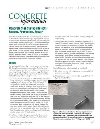
Cracks that occur before hardening usually are the result of set-
tlement within the concrete mass, or shrinkage of the surface
(plastic-shrinkage cracks) caused by rapid loss of water while the
concrete is still plastic (Fig. 2).
Settlement cracks may develop over embedded items, such as
reinforcing steel, or adjacent to forms or hardened concrete as
the concrete settles or subsides. Settlement cracking results from
insufficient consolidation (vibration), high slumps (overly wet
concrete), or a lack of adequate cover over embedded items.
Plastic-shrinkage cracks are relatively short cracks that may occur
before final finishing on days when wind, a low humidity, and a
high temperature occur. Surface moisture evaporates faster than it
can be replaced by rising bleed water, causing the surface to shrink
more than the interior concrete. As the interior concrete restrains
shrinkage of the surface concrete, stresses develop that exceed the
concrete’s tensile strength, resulting in surface cracks. (Under certain
combinations of conditions, warping or curling can result from these
stresses, too. See Curling.) Plastic-shrinkage cracks are of varying
lengths, spaced from a few centimeters (inches) up to 3 m (10 ft)
apart, and often penetrate to middepth of a slab.
Cracks that occur after hardening usually are the result of drying
shrinkage (Fig. 3), thermal contraction, or subgrade settlement.
While drying, hardened concrete will shrink about 1.6 mm in 3 m
(1/16 in. in 10 ft) of length. To accommodate this shrinkage and
control the location of cracks, joints are placed at regular intervals.
Experience has shown that contraction joints (induced cracks)
should be spaced at about 3-m (10-ft) intervals in each direction in
100-mm-thick (4-in.) unreinforced concrete slabs on grade and at
about 6-m (20-ft) intervals in 200-mm-thick (8-in.) slabs.
Figure 2. Plastic-shrinkage cracks
caused by rapid loss of mix water
while the concrete is still plastic.
(1311)
Portland Cement Association
2
3. The major factor influencing the drying-shrinkage properties of
concrete is the total water content of the concrete. As the water
content increases, the amount of shrinkage increases proportion-
ally. Large increases in the sand content and significant reduc-
tions in the size of the coarse aggregate increase shrinkage
because total water is increased and because smaller size coarse
aggregates provide less internal restraint to shrinkage. Use of
high-shrinkage aggregates and calcium chloride admixtures also
increases shrinkage. Within the range of practical concrete
mixes—280 to 445 kg/m3
cement content (470 to 750 lb/yd3
, or
“5- to 8-bag” mixes)—increases in cement content have little to
no effect on shrinkage as long as the water content is not
increased significantly.
Silica fume can make highly cohesive, sticky concrete, with little
bleeding capacity. With little or no bleed water on the surface,
silica fume concrete is prone to plastic shrinkage cracking on
hot, windy days. Fogging the air above the concrete and erecting
windshades lessen the risk of plastic-shrinkage cracking.
Concrete has a coefficient of thermal expansion and contraction
of about 10 x 10-6
per °C (5.5 x 10⁻⁶
per °F). Concrete placed dur-
ing hot midday temperatures will contract as it cools during the
night. A 22°C (40°F) drop in temperature between day and
night—not uncommon in some areas—would cause about
0.7 mm (0.03 in.) of contraction in a 3-m (10-ft) length of con-
crete, sufficient to cause cracking if the concrete is restrained.
Thermal expansion can also cause cracking.
Insufficiently compacted subgrades and soils susceptible to frost
heave or swelling can produce cracks in slabs. Overloading of
concrete slabs also results in flexural crack formation and possi-
ble failure.
Cracking in concrete can be reduced significantly or eliminated
by observing the following practices:
1. Use proper subgrade preparation, including uniform support
and proper subbase material at adequate moisture content.
2. Minimize the mix water content by maximizing the size and
amount of coarse aggregate and use low-shrinkage aggregate.
3. Use the lowest amount of mix water required for workability;
do not permit overly wet consistencies.
4. Avoid calcium chloride admixtures.
5. Prevent rapid loss of surface moisture while the concrete is
still plastic through use of spray-applied finishing aids or plas-
tic sheets to avoid plastic-shrinkage cracks.
6. Provide contraction joints at reasonable intervals, 30 times the
slab thickness.
7. Provide isolation joints to prevent restraint from adjoining ele-
ments of a structure.
8. Prevent extreme changes in temperature.
9. To minimize cracking on top of vapor barriers, use a 100-mm-
thick (4-in.) layer of slightly damp, compactible, drainable fill
choked off with fine-grade material. If concrete must be
placed directly on polyethylene sheet or other vapor barriers,
placed directly on polyethylene sheet or other vapor barriers,
use a mix with a low water content.
10. Properly place, consolidate, finish, and cure the concrete.
11. Avoid using excessive amounts of cementitious materials.
12. Consider using a shrinkage-reducing admixture to reduce
drying shrinkage, which may reduce shrinkage cracking.
13. Consider using synthetic fibers to help control plastic shrink-
age cracks.
Refer to the section on curling for more recommendations on
how to reduce shrinkage.
Cracks can also be caused by freezing and thawing of saturated con-
crete, alkali-aggregate reactivity, sulfate attack, or corrosion of rein-
forcing steel. However, cracks from these sources may not appear for
years. Proper mix design and selection of suitable concrete materials
can significantly reduce or eliminate the formation of cracks and
deterioration related to freezing and thawing, alkali-aggregate reactiv-
ity, sulfate attack, or steel corrosion. For more information, refer to
Design and Control of Concrete Mixtures, EB001, and Diagnosis and
Control of Alkali-Aggregate Reactions in Concrete, IS413.
Crazing
Crazing, a network pattern of fine cracks that do not penetrate
much below the surface, is caused by minor surface shrinkage
Concrete Slab Surface Defects: Causes, Prevention, Repair
Figure 3. Drying-shrinkage cracks like these often result from
improper joint spacing. (A5271)
3
4. Portland Cement Association
Figure 4. Crazing is a network of fine surface cracks. (4099)
(Fig. 4). Crazing cracks are very fine and barely visible except
when the concrete is drying after the surface has been wet. The
cracks encompass small concrete areas less than 50 mm (2 in.)
in dimension, forming a chicken-wire pattern. The term “map
cracking” is often used to refer to cracks that are similar to craz-
ing cracks only more visible and surrounding larger areas of
concrete. Although crazing cracks may be unsightly and can
collect dirt, crazing is not structurally serious and does not ordi-
narily indicate the start of future deterioration.
When concrete is just beginning to gain strength, the climatic con-
ditions, particularly the relative humidity during the drying period
in a wetting and drying cycle, are an important cause of crazing.
Low humidity, high air temperature, hot sun, or drying wind, either
separately or in any combination, can cause rapid surface drying
that encourages crazing. A surface into which dry cement has been
cast to hasten drying and finishing will be more subject to crazing.
The conditions that contribute to dusting, as described below, also
will increase the tendency to craze.
To prevent crazing, curing procedures should begin early, within
minutes after final finishing when weather conditions warrant.
When the temperature is high and the sun is out, some method
of curing with water should be used, since this will stop rapid
drying and lower the surface temperature. The concrete should
be protected against rapid changes in temperature and moisture
wherever feasible.
Curling
Curling is the distortion (rising up) of a slab’s corners and edges
due to differences in moisture content or temperature between
the top and bottom of a slab. The top dries out or cools and
shrinks more than the wetter or warmer bottom. If the curled sec-
tion of a slab is loaded beyond the flexural strength of the con-
crete, cracks may develop to relieve the stress. Curling can be
reduced by:
1. Using a low-shrinkage concrete mix.
2. Using proper control-joint spacing (see Cracking).
3. Creating uniform moisture content and temperature of the slab
from top to bottom.
4. Using large amounts of reinforcing steel 50 mm
(2 in.) down from the surface.
5. Using thickened slab edges.
6. Using vacuum dewatering, shrinkage-compensating concrete,
or post-tensioning.
Shrinkage in a mix can be reduced by (1) using a low water con-
tent, (2) reducing sand content and maximizing the coarse aggre-
gate content, (3) using low-shrinkage and well-graded aggregates
of the largest practical size, (4) avoiding calcium chloride or
other admixtures that may increase shrinkage, and (5) reducing
the temperature of the plastic (fresh) concrete.
Another way to reduce shrinkage of concrete is to use a shrink-
age-reducing admixture (typical dosage, 2%). The reduction in
shrinkage (%) increases with an increase in curing time and with
the use of low water-cementitious materials ratios. Because
shrinkage-reducing admixtures reduce drying shrinkage, they
may lessen the tendency for curling in slabs on grade.
The moisture content can be stabilized by (1) prompt and proper
curing—curing compounds may help reduce moisture differen-
tials by slowing down the rate of moisture loss over a long peri-
od of time, (2) applying moisture-insensitive sealers or coatings
to slab surfaces—do not use vapor-impermeable sealers on slabs
exposed to freezing in the presence of moisture to avoid delami-
nation (use breathable formulations) and (3) where allowable use
a well-drained, coarse granular fill instead of vapor barriers. Fill
and subgrade beneath the slab must not be allowed to become
and remain saturated. If a vapor barrier is required, place about
100 mm (4 in.) of compactible, drainable fill (not sand) over the
vapor barrier. This material can be choked off with a fine-grade
material to reduce friction between the base material and the
slab, and should be damp enough to be compacted, but dry
enough to act as a blotter.
Temperature extremes can be reduced by using insulation over
or under the slab or by controlling the ambient air temperature.
The degree of curling is often significantly reduced with time as
the slab dries and achieves a more uniform moisture content and
temperature. If moisture-related curling persists, one possible
remedy is to pond the slab until it is level again and cut addition-
al control joints where the slab has curled. The success of this
remedy is variable, often depending upon the extent and cause
of the curling. This method creates additional joints, a considera-
tion for slab maintenance.
4
5. Grinding also may restore serviceability. Portland cement grout
can be injected to fill voids and restore bearing in uplifted por-
tions of a slab; after the grout hardens, the surface can be ground
down to its original plane with power grinding equipment.
Delamination
Delaminations are similar to blisters in that delaminated areas of
surface mortar result from bleed water and bleed air being
trapped below the prematurely closed (densified) mortar surface.
The primary cause is finishing the surface before bleeding has
occurred. Delaminations are also more likely to occur when fac-
tors that extend the bleeding time of concrete (e.g. cold substrate)
are combined with factors that accelerate surface setting (e.g.
high ambient air temperature).
It is necessary to wait for a period of time after placing the con-
crete to allow air and water to escape from the concrete. The
waiting period varies with the concrete mixture, mixing and
placing procedures, and weather conditions. Delaminations are
very difficult to detect during finishing and become apparent
after the concrete surface has dried and the delaminated area is
crushed under traffic. The delaminated mortar thickness ranges
from about 3 mm to 5 mm (1/8 in. to 1/4 in.). To avoid condi-
tions that lead to delaminations, see the recommendations under
the section on blisters.
Delaminations also may be the result of disruptive stresses from
chloride-induced corrosion of steel reinforcement or of poorly
bonded areas in two-course construction. The resulting delami-
nations are deeper than those caused by trapped air or bleed
water and are often called spalls (see Spalls).
A delaminated area that has separated from the underlying con-
crete can leave a hole in the surface and resembles spalling (see
Fig. 5). A delamination survey can be conducted by sounding—
dragging a chain across the surface or tapping with a hammer
and listening for hollow sounds. A hollow sound indicates
delaminated areas, and a ringing sound indicates intact areas.
This test is described in ASTM D 4580, Standard Practice for
Measuring Delaminations in Concrete Bridge Decks by
Sounding. Nonstandard methods for detecting delaminated areas
are acoustic impact, infrared thermography, and ground-penetrat-
ing radar. Delaminations can be repaired by patching or, if wide-
spread, by grinding and overlaying with a new surface. Epoxy
injection may also be beneficial in some applications.
Discoloration
Surface discoloration of concrete flatwork can
appear as gross color changes in large areas of
concrete, spotted or mottled light or dark blotches
on the surface, or early light patches of efflores-
cence (see section below).
Laboratory studies to determine the effects of vari-
ous concreting procedures and concrete materials
show that no single factor is responsible for all
discoloration. Factors found to influence discol-
oration are calcium chloride admixtures, cement
alkalies, hard-troweled surfaces, inadequate or
inappropriate curing, a wet substrate, variation of
the water-cement ratio at the surface, and changes
in the concrete mix. Discoloration from these caus-
es appears very soon after placing the concrete.
Discoloration at later ages may be the result of
atmospheric or organic staining—simply stated,
the concrete is dirty. This type of discoloration is
usually removed by power washing with pressur-
ized water and, possibly, chemical cleaners.
The use of calcium chloride in concrete may discolor the surface
(Fig. 6). Calcium chloride accelerates the hydration process but
has a retarding effect on the hydration of the ferrite compound in
portland cement. The ferrite phase normally becomes lighter
with hydration; however, in the presence of calcium chloride the
retarded, unhydrated ferrite phase remains dark.
Extreme discoloration can result from attempts to hard-trowel the
surface after it has become too stiff to trowel properly. Vigorously
troweling a surface to progressively compact it can reach the point
where the water-cement ratio is drastically decreased in localized
areas. This dense, low-water-cement-ratio concrete in the hard-
troweled area is almost always darker than the adjacent concrete.
Waterproof paper and plastic sheets used to moist-cure concrete
containing calcium chloride have been known to give a mottled
appearance to flat surfaces due to the difficulty in placing and
keeping a cover in complete contact with the surface over the
entire area. The places that are in contact will be lighter in color
than those that are not.
Concrete materials and proportions affect concrete color. Individual
cements may differ in color. Thus, substituting one cement for
Figure 5. This delamination is the result of sealing the surface before bleeding
has occurred. (67196)
5
Concrete Slab Surface Defects: Causes, Prevention, Repair
6. Figure 6. Driveway discoloration due to the use of a calcium chloride admixture in the concrete at the bottom but not the top of
the photo. This illustrates just one of several types of discoloration. (14019)
another may change the color of concrete. Concretes containing
significant amounts of mineral admixtures—fly ash, silica fume,
metakaolin, or slag, for example—may differ in color from those
containing no mineral admixture. The color of the sand has an
effect on the color of the concrete. High-strength concrete with a
low water-cement ratio is darker in color than low-strength con-
crete with a high water-cement ratio.
The discoloration of concrete can be avoided or minimized by
(1) avoiding the use of calcium chloride admixtures, (2) using
consistent concrete ingredients, uniformly proportioned from
batch to batch, and (3) using proper and timely placing, finish-
ing, and curing practices. Concreting practices should not be
allowed to vary, as any disruption or change in the concrete
mixture, formwork, finishing, or curing can result in significant
and sometimes permanent discoloration.
To eradicate discoloration, the first (and usually effective) remedy
is an immediate, thorough flushing with water. Permit the slab to
dry, then repeat the flushing and drying until the discoloration
disappears. If possible, use hot water. Acid washing using con-
centrations of weaker acids such as 3% acetic acid (vinegar) or
3% phosphoric acid will lessen carbonation and mottling discol-
oration. Treating a dry slab with 10% solution of caustic soda
(sodium hydroxide) gives some success in blending light spots
into a darker background. Harsh acids should not be used, as
they can expose the aggregate.
One of the best methods to remove most discoloration, when
other remedies have failed, is to treat a surface with a 20% to
30% water solution of diammonium citrate. This chemical is
expensive to buy in small quantities, so consider it as a last
resort. These and other treatments and recommendations to pre-
vent and eradicate discoloration are contained in Surface
Discoloration of Concrete Flatwork, RX203; “Discoloration of
Concrete—Causes and Remedies,” Concrete Technology Today,
PL861; “Pinto Concrete—Is There a Cure?” Concrete Technology
Today, PL961; and “Reader Response: Discoloration,” Concrete
Technology Today, PL962.
Staining discolored concrete with a chemical stain is another
way to make color variations less noticeable. Usually, darker col-
ors hide color variations more effectively. Chemical stains can be
used on interior or exterior concrete.
A rare discoloration ranging in color from buff to red/orange has
been reported in Wisconsin, Illinois, Louisiana, and other states.
This type of discoloration is more likely to occur during periods
of high relative humidity and high ambient temperature. This
staining occurs more often with certain types and amounts of
6
Portland Cement Association
7. Dusting
Dusting—the development of a fine, powdery material that easily
rubs off the surface of hardened concrete—can occur either
indoors or outdoors, but is more likely to be a problem when it
occurs indoors (Fig. 7). Dusting is the result of a thin, weak layer,
called laitance, composed of water, cement, and fine particles.
Fresh concrete is a fairly cohesive mass, with the aggregates,
cement, and water uniformly distributed throughout. A certain
amount of time must elapse before the cement and water react
sufficiently to develop hardened concrete. During this period, the
cement and aggregate particles are partly suspended in the water.
Because the cement and aggregates are heavier than water, they
tend to sink. As they move downward, the displaced water moves
upward and appears at the surface as bleed water, resulting in
more water near and at the surface than in the lower portion of
the concrete. Thus, the laitance—the weakest, most permeable,
and least wear-resistant concrete—is at the top surface, exactly
where the strongest, most impermeable, and most wear-resistant
concrete is needed.
Floating and troweling concrete with bleed water on it mixes the
excess water back into the surface, further weakening the con-
crete’s strength and wear resistance and giving rise to dusting.
Dusting may also be caused by (1) water applied during finishing,
(2) exposure to rainfall during finishing, (3) spreading dry cement
over the surface to accelerate finishing, (4) a low cement content,
(5) too wet a mix, (6) lack of proper curing (especially allowing
Figure 7. Dusting is evident by the fine powder that can be easily rubbed off the surface. (1297)
7
Concrete Slab Surface Defects: Causes, Prevention, Repair
wet-curing. Fly ash aggravates the staining by intensifying the
color.
This staining is probably caused by differences in curing and
degree of hydration of the surface cementitious materials under
high humidity and high ambient temperature conditions. In partic-
ular, additional hydration of the ferrite compounds in cementi-
tious materials leads to more reduced iron being available to oxi-
dize and discolor the concrete. Research has found that the stain-
ing occurs under a certain set of conditions, which includes the
availability of water and oxygen. Rapid drying of the concrete
results in insufficient moisture to produce staining, while continu-
ous immersion does not allow access of air. In both cases, discol-
oration does not occur. Therefore, it is recommended that the
concrete be kept fully wet for the required curing period, then
allowed to dry as rapidly as possible thereafter. For instance, wet
burlap with a plastic sheet covering should be removed in the
morning of a hot day rather than in the evening or before rain is
expected.
This type of staining is difficult to remove. Commercial sodium
bisulfate cleaners are somewhat successful in removing the
stain; however, the difference between cleaned and stained
areas decreases over several weeks. The following chemicals are
largely ineffective at removing these buff to red/orange stains:
hydrochloric acid (2%), hydrogen peroxide (3%), bleach, phos-
phoric acid (10%), diammonium citrate (0.2M), and oxalic acid
(3%). (Miller, Powers, and Taylor 1999, and Taylor, Detwiler,
and Tang 2000)
8. Efflorescence
Efflorescence can be considered a type of discoloration. It is a
deposit, usually white in color, that occasionally develops on the
surface of concrete, often just after a structure is completed.
Although unattractive, efflorescence is usually harmless. In rare
cases, excessive efflorescence deposits can occur within the sur-
face pores of the material, causing expansion that may disrupt
the surface.
Efflorescence is caused by a combination of circumstances: solu-
ble salts in the material, moisture to dissolve these salts, and evap-
oration or hydrostatic pressure that moves the solution toward the
surface. Water in moist, hardened concrete dissolves soluble salts.
This salt-water solution migrates to the surface by evaporation or
hydraulic pressure where the water evaporates, leaving a salt
deposit at the surface. Efflorescence is particularly affected by tem-
perature, humidity, and wind. In the summer, even after long rainy
periods, moisture evaporates so quickly that comparatively small
amounts of salt are brought to the surface. Usually efflorescence is
more common in the winter when a slower rate of evaporation
allows migration of salts to the surface. If any of the conditions that
cause efflorescence—water, evaporation, or salts—are not present,
efflorescence will not occur.
8
Portland Cement Association
rapid drying of the surface), (7) carbonation during winter con-
creting (caused by unvented heaters), (8) freezing of the surface,
and (9) dirty aggregate.
Heated enclosures are commonly used for protecting concrete
when air temperatures are near or below freezing. The enclo-
sures frequently are heated by oil- or propane-fired blowers or
coke-burning salamanders. As these heaters produce a dry heat,
care must be taken to prevent rapid drying of the concrete sur-
face, especially near the heater. The burning of fuel also pro-
duces carbon dioxide that will combine with the calcium
hydroxide in fresh concrete to form a weak layer of calcium car-
bonate on the surface. When this occurs, the floor surface will
dust under traffic. For this reason, carbon dioxide-producing
heaters should not be used while placing and finishing concrete
and during the first 24 to 36 hours of the curing period unless
properly vented to outside the heated enclosure.
One way to correct a dusting surface is to grind off the thin layer
of laitance to expose the solid concrete underneath. Another
method is to apply a surface hardener. This treatment will not
convert a basically bad concrete slab into a good one; it will,
however, improve wearability and reduce dusting of the surface.
The major ingredient in many floor-surface hardeners is sodium
silicate (water glass) or a metallic silicofluoride (magnesium and
zinc fluosilicates are widely used). The treatment is usually
applied in two or three coats, letting the surface dry between
each application. More information is available in Concrete
Floors on Ground, EB075.
All concrete materials are susceptible to efflorescence. Even small
amounts of water soluble salts (a few tenths of a percent) are suffi-
cient to cause efflorescence when leached out and concentrated
at the surface. In most cases, these salts come from beneath the
surface, but chemicals in the materials can react with chemicals
in the atmosphere to form efflorescence. For example, hydration
of cement in concrete produces soluble calcium hydroxide, which
can migrate to the surface and combine with carbon dioxide in
the air to form a white calcium carbonate deposit.
All concrete ingredients should be considered for soluble-salt con-
tent. Common efflorescence-producing salts are carbonates of cal-
cium, potassium, and sodium; sulfates of sodium, potassium, mag-
nesium, calcium, and iron; and bicarbonate of sodium or silicate
of sodium. To reduce or eliminate soluble salts:
1. Never use unwashed sand. Use sand that meets the require-
ments of ASTM C 33 or CSA A23.1 for concrete.
2. Use clean mixing water free from harmful amounts of acids,
alkalies, organic material, minerals, and salts. Drinking water
is usually acceptable. Do not use seawater.
Low absorption of moisture is the best assurance against efflores-
cence. Cast-in-place concrete will have maximum watertightness
when made with properly graded aggregates, an adequate cement
content, a low water-cement ratio, and thorough curing.
When there is efflorescence, the source of moisture should be
determined and corrective measures taken to keep water out of
the structure. Chloride salts are highly soluble in water, so the
first rain often will wash them off the surface of concrete. With
the passage of time, efflorescence becomes lighter and less
extensive unless there is an external source of salt. Light-colored
surfaces show the deposits much less than darker surfaces. Most
efflorescence can be removed by dry brushing, water rinsing
with brushing, light waterblasting or light sandblasting, followed
by flushing with clean water. If this is not satisfactory, it may be
necessary to wash the surface with a dilute solution of muriatic
acid (1 to 10 percent). For integrally colored concrete, only a 1
to 2 percent solution should be used to prevent surface etching
that may reveal the aggregate and hence change color and tex-
ture. Always pretest the treatment on a small, inconspicuous
area to be certain there is no adverse effect. Before applying an
acid solution, always dampen concrete surfaces with clean
water to prevent the acid from being absorbed deeply where
damage may occur. The cleaning solution should be applied to
no more than 0.4 m2 (4 ft2) at one time to avoid surface dam-
age. Wait about 5 minutes, then scour with a stiff bristle brush.
Immediately rinse with clean water to remove all traces of acid.
The entire concrete element should be treated to avoid discol-
oration or mottled effects. Surfaces to be painted should be thor-
oughly rinsed with water and allowed to dry. See “Efflorescence:
Causes, Prevention Repair,” Concrete Technology Today, PL871.
Low Spots
Low spots can affect slab drainage or serviceability if items
placed on the slab need to be level. Low spots are often caused
9. Concrete Slab Surface Defects: Causes, Prevention, Repair
9
Popouts
A popout is a conical fragment that breaks out of
the surface of the concrete leaving a hole that
may vary in size generally from 5 mm to 50 mm
(1/4 in. to 2 in.) but up to as much as 300 mm
(1 ft) in diameter (Fig. 8). Usually a fractured
aggregate particle will be found at the bottom of
the hole, with part of the aggregate still adhering
to the point of the popout cone.
The cause of a popout usually is a piece of
porous rock having a high rate of absorption and
relatively low specific gravity. As the offending
aggregate absorbs moisture or freezing occurs
under moist conditions, its swelling creates inter-
nal pressures sufficient to rupture the concrete
surface. Pyrite, hard-burned dolomite, coal, shale,
soft fine-grained limestone, or chert commonly
cause popouts. Popouts may also occur to relieve
pressure created by water uptake of expansive gel
formed during the chemical reaction between the
alkali hydroxides in the concrete and reactive
siliceous aggregates.
Figure 9. Scaling is a scabrous condition where the surface mortar has peeled
away, usually exposing the coarse aggregate. (A5273)
by poor lighting during placement and finishing, improperly set
forms and screeds, damage to form and screed grade settings
during construction, use of overly wet or variably wet concrete,
and poor placement and finishing techniques.
Low spots can be avoided by (1) using a low-slump, low-water-con-
tent concrete mix, (2) providing adequate light, (3) frequently check-
ing grades and levels, and filling the low areas, (4) using a vibrating
screed for strikeoff, and (5) using a “highway” straightedge in lieu of
a bullfloat to smooth and straighten the surface.
Most popouts appear within the first year after placement.
Popouts caused by alkali-silica reactivity (ASR) may occur as
early as a few hours to a few weeks, or even a year, after the
concrete is placed. Popouts caused by moisture-induced
swelling may occur shortly after placement due to the absorp-
tion of water from the plastic concrete, or they may not appear
until after a season or year of high humidity or rainfall or after
the concrete has been exposed to freezing temperatures.
Popouts are considered a cosmetic detraction and generally do
not affect the service life of the concrete.
The following steps can be taken to minimize or
eliminate popouts:
1. Use concrete with the lowest water content and
slump possible for the application.
2. Use a durable crushed-stone or beneficiated-
aggregate concrete.
3. During hot, dry, and windy weather, cover the
surface with plastic sheets after screeding and
bullfloating to reduce evaporation before final
finishing. This reduces the migration of alkalies
to the surface due to drying and therefore helps
reduce popouts caused by alkali-silica reactivity
(ASR).
4. Do not finish concrete with bleed water on the
surface.
5. Avoid hard-steel troweling where not needed,
such as most exterior slabs.
6. Avoid use of vapor barriers. If required, cover the
vapor barrier with 100 mm (4 in.) of compactible
granular fill, slightly dampened, and choked off
Figure 8. A popout is a small fragment of concrete surface that has broken away
due to internal pressure, leaving a shallow, typically conical, depression. (0113)
10. Figure 10. Mortar flaking over coarse aggregate. (52225)
10
Portland Cement Association
with a fine-grade material to reduce friction between the base
material and the slab. This material should be dry enough to
act as a blotter for the concrete placed over it.
7. Use wet-curing methods such as continuous sprinkling with
water, fogging, ponding, or covering with wet burlap soon after
final finishing. Wet-cure for a minimum of 7 days, as wet cures
can greatly reduce or eliminate popouts caused by ASR. Avoid
plastic film, curing paper, and especially curing compounds as
they allow an accumulation of alkalies at the surface. Flush
curing water from the surface before final drying. Impervious
floor coverings or membranes should be avoided as they can
aggravate popout development.
8. Use a blended cement or a supplementary cementitious materi-
al such as fly ash (proven to control ASR) where popouts are
caused by alkali-silica reactivity. Use of a low-alkali cement is
also beneficial.
9. Use two-course construction with clean, sound rock in the top-
ping, and the offending aggregates in the base slab, thus limit-
ing the susceptible aggregate’s exposure to excess moisture.
10. Slope the slab surface to drain water properly.
11. Use air-entrained concrete.
12. Reduce concrete temperature to 10°C to 20°C (50°F to 70°F).
Surfaces with popouts can be repaired. A small patch can be
made by drilling out the spalled particle and filling the void with
a dry-pack mortar or other appropriate patch material. If the
popouts in a surface are too numerous to patch individually, a
thin-bonded concrete overlay may be used to restore servicea-
bility.
For more information on popouts, refer to “Popouts: Causes,
Prevention, Repair,” Concrete Technology Today, PL852.
Scaling and Mortar Flaking
Scaling is the general loss of surface mortar exposed to freezing
and thawing. The aggregate is usually clearly exposed and often
stands out from the concrete (Fig. 9). Scaling is primarily a phys-
ical action caused by hydraulic pressure from water freezing
within the concrete and not usually caused by chemical corro-
sive action. When pressure exceeds the tensile strength of con-
crete, scaling can result if entrained-air voids are not present to
act as internal pressure relief valves.
The presence of a deicer solution in water-soaked concrete dur-
ing freezing causes an additional buildup of internal pressure.
11. Deicers such as sodium chloride, urea, and weak
solutions of calcium chloride do not chemically
attack concrete; however, deicers containing ammo-
nium sulfate or ammonium nitrate will rapidly disin-
tegrate concrete and should not be used. Several
deicers, particularly those containing chloride, can
also cause corrosion of embedded steel.
ACI 116R, Cement and Concrete Terminology,
defines light, medium, severe, and very severe scal-
ing as ranging from no exposure of coarse aggregate
up to a loss of mortar and coarse aggregate particles
to a depth of greater than 20 mm (0.8 in.).
Mortar flaking over coarse aggregate particles (Fig.
10), sometimes called popoffs, is another form of scal-
ing that somewhat resembles a surface with popouts.
However, mortar flaking usually does not result in
freshly fractured aggregate particles and there are
fewer, if any, conical voids such as those found in
popouts. Aggregate particles with flat surfaces are
more susceptible than round particles to this type of
defect. Mortar flaking occasionally precedes more
widespread surface scaling, but its presence does not
necessarily lead to more extensive scaling.
Mortar flaking over coarse aggregate particles is
caused essentially by the same actions that cause
regular scaling. Excessive and early drying out of the
surface mortar can alone aggravate scaling.
However, the moisture loss is accentuated over
aggregate particles near the surface. The lack of
moisture necessary for cement hydration results in a
mortar layer of lower strength and durability, higher
shrinkage, and poorer bond with the aggregate.
Upon freezing in a saturated condition, this thin,
weakened mortar layer breaks away from the aggre-
gate. Poor finishing practices can also aggravate
mortar flaking.
Field service experience and extensive laboratory testing have
shown that when properly spaced air voids are present, air-
entrained concrete will have excellent resistance to surface
scaling and mortar flaking due to freezing and thawing and the
application of deicer chemicals, provided the concrete is prop-
erly proportioned, placed, finished, and cured. The following
practices are recommended:
1. Use a proper concrete mix with durable and well-graded
aggregate, a low slump—maximum of 100 mm (4 in.); ade-
quate compressive strength prior to exposure to repeated
cycles of freezing and thawing—a minimum of 28 MPa (4000
psi); low water-cement ratio—0.45 or less; purposely entrained
air—5 to 8 percent total air content; and a minimum cementi-
tious materials content of 335 kg/m3 (564 lb/yd3) of concrete.
For concrete exposed to deicing chemicals, ACI 318/ACI 318R
(ACI Building Code Requirements for Structural Concrete and
Commentary) places a limit on the total allowable percentage
of mineral admixture: 25% for fly ash, 50% for slag, and 10%
for silica fume. Wet, sloppy, low-strength concrete with low
Figure 11. A typical location for a spall is along a joint, usually the result of
the joint functioning improperly. (67216)
11
Concrete Slab Surface Defects: Causes, Prevention, Repair
cement content and without entrained-air voids is prone to
scale at an early age, often after the first or second winter in
severe climates where deicers are used.
2. Properly slope the concrete to drain water away from the
slab; saturated concrete is much more susceptible to deterio-
ration than drier concrete.
3. Use proper finishing practices. Concrete that is prematurely
floated or troweled while added water or bleed water is on
the surface tends to scale when subjected to saturated freez-
ing. Remixing water into the top of the slab can cause the for-
mation of a crust of surface laitance that will scale. In addi-
tion, finishing concrete before the bleed water comes to the
surface can entrap water under the finished surface, forming a
weakened zone or void, which can result in scaling or surface
delamination.
4. Cure promptly with wet burlap (kept continuously wet), cur-
ing paper, or plastic sheet for a minimum of 7 days (longer
when temperatures are around 4°C (40°F), or until the con-
12. Figure 12. Corrosion of steel reinforcement is an expansive process, which can cause
pressure within the concrete and lead to this type of concrete spall. (67217)
12
Portland Cement Association
crete attains 70 percent of the specified strength in cases
where the curing period is followed by an air-drying period.
Curing compounds may also be used on spring and summer
placements.
5. After curing, allow the concrete 30 days to air dry. Concrete
that may not have sufficient time to dry before being exposed
to freezing temperatures, such as that placed later in the year,
should not have deicing chemicals applied during its first
winter season. Instead, if traction is required over ice or
snow, sand can be used.
If scaling or mortar flaking should develop, or if the concrete is
suspected of having poor quality, a breathable surface treatment
may be applied to help protect the concrete against further
freeze-thaw damage. These treatments are made with linseed
oil, silane, siloxane, or other materials.
Oil treatment normally consists of two applications of equal
parts of commercial boiled linseed oil and a solvent such as tur-
pentine, naphtha, or mineral spirits. Recommended coverages
are 9 to 11 m
2
/liter (40 to 50 yd
2
/gal) for the first application and
about 15 m
2
/liter (70 yd
2
/gal) for the second application. The
temperature of the concrete should be 10°C (50°F) or above at
the time of application to assure proper penetration and to has-
ten drying. Applying a sealer is best done as the concrete is
cooling down rather than heating up, which usually occurs in
the early evening. This helps draw the sealer deeper into the
concrete rather than allow the vapors to push it out of the pores.
Since oil treatment will produce a slippery surface until
absorbed, it may be necessary to keep traffic off the concrete
until sufficient drying has taken place.
Impermeable materials, such as most epoxies, should not be
used on slabs on ground or other concrete where moisture can
freeze under the coating. The freezing water can cause delami-
nation under the impermeable coating; therefore, a breathable
surface treatment should be used.
Thin-bonded overlays or surface-grinding methods can usually
remedy a scaled surface if sound, air-entrained concrete is pres-
ent below the scaled surface.
Spalling
Spalling is a deeper surface defect than scaling, often appearing
as circular or oval depressions on surfaces or as elongated cavi-
ties along joints. Spalls may be 25 mm (1 in.) or more in depth
and 150 mm (6 in.) or more in diameter, although smaller spalls
also occur. Spalls are caused by pressure or expansion within
the concrete, bond failure in two-course construction, impact
loads, fire, or weathering. Improperly constructed joints and cor-
roded reinforcing steel are two common causes of spalls (see
Figs. 11 and 12). If left unrepaired, spalls can accelerate pave-
ment deterioration. However, shallow spalls along joints in
roads, no more than 75 mm wide by 300 mm long (3 x 6 in.),
often do not affect ride of automobiles, and are not repaired.
Spalls can be avoided by (1) properly designing the concrete ele-
ment—including joints—for the environment and anticipated
service, (2) using proper concrete mixes and concreting prac-
tices, and (3) taking special precautions where necessary. The
first line of defense against steel corrosion caused by chloride-
ion ingress (for example, from deicers) should be the use of a
low permeability concrete made with a water-cement ratio of
0.4 or less. If steel reinforcement is used, it should have ade-
quate cover as outlined in ACI 318. For extreme conditions, the
addition of silica fume or latex to a concrete mix will dramati-
cally lower its permeability. Other examples of special precau-
tions to reduce steel corrosion induced by chloride-ion ingress
in extreme conditions are (1) the use of epoxy-coated reinforcing
13. Figure 13. Self-leveling toppings can be used to restore the floor
surface on an otherwise sound slab. Underlayments usually
require a floor covering material such as tile or carpet. (69682)
13
Concrete Slab Surface Defects: Causes, Prevention, Repair
steel (ASTM D 3963), (2) application of breathable surface seal-
ers such as silane, siloxane, and methacrylate-based com-
pounds, (3) the use of corrosion-inhibiting admixtures, and (4)
cathodic protection methods. These methods may be combined
for added protection.
Spalled areas of concrete can be repaired when no more than the
top 1/3 of the pavement is damaged and the underlying pavement
is sound: if more than the top 1/3 of the pavement is damaged, if
steel reinforcement bars are uncovered, or if spalls are a result of
misaligned dowel bars or D-cracking, a full-depth repair is
required. The economics of partial-depth repair versus complete
replacement should be considered, as it may be more cost effec-
tive (and more uniform-looking) to replace the entire area.
Concrete should be removed to a depth of at least 40 mm (1-1/2
in.). The boundaries of the repair area should be determined by
sounding the pavement for delaminated or unsound areas. Patch
limits should be extended about 100 mm (4 in.) beyond the
edges of the unsound areas. Spalled or delaminated concrete is
removed by sawing and chipping or by milling. If jackhammers
are used, they should be small—no greater than 15-kg (30-lb)—
to prevent concrete damage beyond the repair area. It is best to
keep the area rectangular or square and provide vertical edges at
the boundaries to contain the patch. The exposed concrete
should be lightly sandblasted to clean and roughen the surface
so that good bond can be obtained with the repair material.
Patching materials can be portland-cement-based, rapid strength
proprietary materials, or polymer concretes (epoxy, methyl
methacrylate, and polyurethane). Bituminous materials have also
been used, but are usually considered temporary. Patch materials
should have a thermal expansion coefficient that is compatible
with the underlying concrete. Some materials are formulated to
work with a bonding agent; other materials require only a clean
surface for good bond. Patch materials are usually mixed in
small quantities to assure prompt placement (without segrega-
tion), consolidation, finishing, and curing. The air temperature at
placement needs to be above 4°C (40°F) for all cement-based
patches and many of the proprietary rapid-setting mixes. The
polymer concretes can be applied at lower temperatures and to
wet substrates, but perform better when placed under more
favorable conditions. Wet curing methods (spraying, wet cover-
ings) reduce shrinkage of patch materials more than sealed cur-
ing (sheet materials, curing compounds). When spall repair
involves a joint, the joint must be restored to proper working
condition to allow for thermal expansion of the slab. This is one
of the most important steps to ensure that partial-depth repairs
will function properly. Sealants placed in joints keep out non-
compressible materials and allow free joint movement. Consult
manufacturers for further recommendations on patching materi-
als and placement methods.
Thin Toppings and Underlayments
A number of proprietary materials are available for topping and
underlayment of concrete slabs. These materials are generally
portland-cement-based, nonshrink, and are frequently self-level-
ing (Fig. 13). They are primarily used to restore the floor surface
on an otherwise sound slab. Topping materials provide the wear-
ing surface, and underlayments require a floor covering material
such as tile or carpet. Applications less than 25-mm (1-in.) thick
are normally bonded to the slab and require a primer for this
purpose. Thicker applications—up to 100 mm (4 in.)—may or
may not require a primer. Adding aggregate to the formulation
reduces shrinkage. Consult the manufacturer on the use and
installation of these products. See Resurfacing Concrete Floors
(IS144) for more information.
Analysis of Surface Defects
The cause of most concrete defects can be determined by petro-
graphic (microscopical) analysis on samples of the concrete (Fig.
14). A petrographic analysis of concrete is performed in accor-
dance with the American Society for Testing and Materials’
Standard Practice for Petrographic Examination of Hardened
Concrete, ASTM C856.
Samples for the analysis are usually drilled, 100-mm (4-in.) diameter
cores or saw-cut sections. Broken sections can be used, but cores or
saw-cut sections are preferred because they are less apt to be dis-
turbed. Samples should represent concrete from both problem and
nonproblem areas. The petrographer should be provided with a
14. Portland Cement Association
14
Figure 14. The cause of most concrete surface defects can be
determined by petrographic analysis. (64241)
description and photographs of the problem, plus information on
mix design, construction practices used, and environmental condi-
tions. A field review by a petrographer, engineer, or concrete tech-
nologist is also helpful in analyzing the defect.
The petrographic report often includes the probable cause of the
problem, extent of distress, general quality of the concrete, and
expected durability and performance of the concrete. Corrective
action, if necessary, would be based to a great extent on the pet-
rographic report. Additional information on petrography is avail-
able through the Portland Cement Association.
15. References
Miller, F. MacGregor, Powers, Laura J., and Taylor, Peter C., Investigation of
Discoloration of Concrete Slabs, Serial No. 2228, Portland Cement
Association, 1999, 22 pages.
Taylor, Peter C., Detwiler, Rachel J., and Tang, Fulvio J., Investigation of
Discoloration of Concrete Slabs (Phase 2), Serial No. 2228b, Portland
Cement Association, 2000, 22 pages.
Related Publications
The following related publications are available for purchase from PCA.
To order, write, call, or fax Order Processing, Portland Cement Association,
PO Box 726, Skokie, IL 60076-0726
Phone: 847-966-6288, Fax 847-966-9666.
Or visit PCA’s Web site at http://www.portcement.org.
Design and Control of Concrete Mixtures, EB001
Concrete Floors on Ground, EB075
Effects of Substances on Concrete and Guide to Protective Treatments, IS001
Resurfacing Concrete Floors, IS144
Building Concrete Walks, Driveways, Patios, and Steps, IS209
Removing Stains and Cleaning Concrete Surfaces, IS214
Diagnosis and Control of Alkali-Aggregate Reactions in Concrete, IS413
Guide Specification for Concrete Subject to Alkali-Silica Reactions, IS415
Cement Mason’s Guide, PA122
“Slab Curling is Not a Game Played on Ice,” Concrete Technology Today, PL822
“Repair with Thin-Bonded Overlay,” Concrete Technology Today, PL851
“Popouts: Causes, Prevention, Repair,” Concrete Technology Today, PL852
“Discoloration of Concrete—Causes and Remedies,” Concrete Technology
Today, PL861
“Petrographic Analysis of Concrete,” Concrete Technology Today, PL862
“Efflorescence: Causes, Prevention Repair,” Concrete Technology Today, PL871
“Cleaning Concrete Pavements by Powerwashing,” Concrete Technology
Today, PL953
Effect of Fly Ash on the Durability of Air-Entrained Concrete, RD090
Strength and Durability of Residential Concretes Containing Fly Ash, RD099
Surface Discoloration of Concrete Flatwork, Research Department Bulletin RX203
The Homeowner’s Guide to Building with Concrete, Brick & Stone, SP038
Concrete Repair and Material Considerations, SS374 (slide set)
Surface Defects, SS380 (slide set)
Guidelines for Partial-Depth Repair, TB003 (American Concrete Pavement
Association)
Concrete Petrography, John Wiley & Sons Inc., LT226
A complete listing of PCA publications, computer software, audiovisual
materials, and educational courses can be found in PCA’s catalog, MS254.
The catalog is free upon request.
16. WARNING: Contact with wet (unhardened) concrete, mortar,
cement, or cement mixtures can cause SKIN IRRITATION, SEVERE
CHEMICAL BURNS (THIRD-DEGREE), or SERIOUS EYE DAMAGE.
Frequent exposure may be associated with irritant and/or allergic
contact dermatitis. Wear waterproof gloves, a long-sleeved shirt,
full-length trousers, and proper eye protection when working with
these materials. If you have to stand in wet concrete, use waterproof
boots that are high enough to keep concrete from flowing into them.
Wash wet concrete, mortar, cement, or cement mixtures from your
skin immediately. Flush eyes with clean water immediately after
contact. Indirect contact through clothing can be as serious as
direct contact, so promptly rinse out wet concrete, mortar, cement,
or cement mixtures from clothing. Seek immediate medical atten-
tion if you have persistent or severe discomfort.
This publication is intended SOLELY for use by PROFESSIONAL PER-
SONNEL who are competent to evaluate the significance and limita-
tions of the information provided herein, and who will accept total
responsibility for the application of this information. The Portland
Cement Association DISCLAIMS any and all RESPONSIBILITY and
LIABILITY for the accuracy of and the application of the information
contained in this publication to the full extent permitted by law.
ISBN No. 0-89312-212-Z IS177.07
5420 Old Orchard Road
Skokie, Illinois 60077-1083 USA
Phone: 847.966.6200
Fax: 847.966.9781
Internet: www.portcement.org
An organization of cement companies to improve
and extend the uses of portland cement and concrete
through market development, engineering, research,
education, and public affairs work.
PCA R&D Serial No. 2155