Streamlining Python Development: A Guide to a Modern Project Setup
Shimpo circulute 3000_catalog
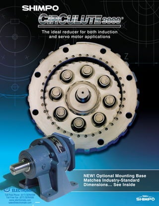
1. The ideal reducer for both induction
and servo motor applications
NEW! Optional Mounting Base
Matches Industry-Standard
Dimensions… See Inside
ELECTROMATE
Toll Free Phone (877) SERVO98
Toll Free Fax (877) SERV099
www.electromate.com
sales@electromate.com
Sold & Serviced By:
2. 2 SHIMPO DRIVES, INC. / 1701 GLENLAKE AVE ITASCA IL 60143 / P: 800.842.1479 / F: 630.924.7382 / WWW.SHIMPODRIVES.COM / INFO@SHIMPODRIVES.COM
Cross sectional view of a precision backlash
Reducer. The two piece pin housing provides the ability to preload
one wheel against the other, reducing the output shaft backlash to
less than 6 arc-min. The extra support bearing prevents fretting
corrosion between the quill input shaft and the motor shaft. The
long output shaft bearing span provides exceptional overhung
load capabilities.
Features & Benefits.......................2-3
Operating Principles ........................4
Model Examples...............................5
Selection Procedures....................6-7
Load Classification Table.................8
Model Number Chart .......................9
Rating Tables.............................10-16
Internal Inertia, Torsional Stiffness, &
Standard Lubrication .....................17
Dimensions-Single Reduction
Base Mount ...............................18-19
Flange Mount ............................20-21
Ring Mount ................................22-23
Dimensions-Double Reduction
Double Reduction Tables..........24-25
Shovel Base & Top Mount
Adaptor ...........................................26
C-Face Adaptor..............................26
Reducers for Overhead Conveyor
Applications....................................27
Overhung Load &
Miscellaneous.........................28-31
Output shaft Output shaft bearings Internal pin housing
Internal pin
Wheels
Carrier pins
Input shaft
Eccentric roller bearings
Mounting housing
Contents
The Speed Reducer delivers the features
today’s industry needs. High reduction ratios, without
sacrificing efficiency. Compact designs, without requiring
special motors. Exceptional shock load capacity, without
having to oversize. Greater overhung load capacities,
without using expensive special components. A precision
backlash option, without resorting to special gearing. All
of this, while requiring minimal maintenance.
is available with mounting and output shaft
dimensions equivalent to those of the SM Cyclo® product.
Your Shimpo reducer can be dropped in to replace the
other brand with no modifications to your mounting
plate! This dimensional change is only available on base-
mounted units. When ordering, specify the “DI” option.
Great Features, Precision
Backlash!
Optional Mounting
Dimensions
ELECTROMATE
Toll Free Phone (877) SERVO98
Toll Free Fax (877) SERV099
www.electromate.com
sales@electromate.com
Sold & Serviced By:
3. 3SHIMPO DRIVES, INC. / 1701 GLENLAKE AVE ITASCA IL 60143 / P: 800.842.1479 / F: 630.924.7382 / WWW.SHIMPODRIVES.COM / INFO@SHIMPODRIVES.COM
• Single stage reduction ratios up to 71:1 saves space
• Rolling motion minimizes friction and wear, reducing heat,
resulting in a 95% efficiency rating per stage
• 500% shock load capability as there are only compressive forces
rather than shear forces on the tooth
• Low speed of cycloidal wheel results in minimal reflected inertia,
less wear, and extremely long service life
• Due to the large overall “tooth / pin” contact area, select a
Reducer using smaller mechanical service factors
• Standard backlash offers the highest available torque rating at an
economical price
• Precision backlash results in tighter positional tolerances
Two Backlash Ratings
Multiple Inputs: NEMA C-Face,
Servo Square Flange, Shaft Input,
Shovel Base, Top Mount
Straddle Mount Output Shaft
Bearings
(sizes D, E, F)
Features & Benefits
High Efficiency Cycloidal Reducer
Design
• Supports output shaft and drive pins to provide exceptional
overhung and thrust load capability, without the need for special
bearings or housings
Multiple Mounting Options: Base,
Flange, Ring
• Versatility to fit anywhere on your machine
• Ring style allows output bearing to extend well within the machine
for greatest overhung load rating
Design Features Operational Benefits
Mounting Options
Base Mount Flange Mount Ring Mount
• Versatility to fit whatever prime mover is needed for the
application
• NEMA and servo input flanges are compact “quill-style” hollow-
bore configuration, eliminating input couplings and guards
• Quill-style input features an input support bearing to control
fretting corrosion between motor shaft and reducer hub, and
permit tighter internal tolerances
• NEMA input flange includes threaded back-off holes for easy
motor removal
ELECTROMATE
Toll Free Phone (877) SERVO98
Toll Free Fax (877) SERV099
www.electromate.com
sales@electromate.com
Sold & Serviced By:
4. 4 SHIMPO DRIVES, INC. / 1701 GLENLAKE AVE ITASCA IL 60143 / P: 800.842.1479 / F: 630.924.7382 / WWW.SHIMPODRIVES.COM / INFO@SHIMPODRIVES.COM
The reduction ratio of the Speed Reducer can
be calculated using the following formula:
Operating Principles
1. When the input shaft makes one rotation, the eccentric roller
bearing also rotates once in the same direction.
2. The wheel is driven by the eccentric roller bearing.
It revolves around the internal pins with its teeth engaging with
consecutive pins.
3. When the eccentric roller bearing has completed one full rotation,
a tooth initially in mesh with a pin will be positioned
as many teeth behind its initial position as the difference between
the number of internal pins and the number of teeth.
As a result, the wheel rotates slowly in the
opposite direction of the input shaft.
4. The rotational motion of the wheel is transmitted to
the output shaft through the carrier pins.
N - M
M
R =
18 - 17
17
R =
1
17
= 17:1=
R = the reduction ratio
N = the number of internal pins
M = the number of teeth
Example: N=18 and M=17,
The power train sets
apart from
other speed reducers.
Its main power transmission
components include: an
eccentric roller bearing
drives a wheel around a
set of internal pins, keeping
rotational inertia low.
The result: exceptional
efficiency, long service life,
and reduced wear.
ELECTROMATE
Toll Free Phone (877) SERVO98
Toll Free Fax (877) SERV099
www.electromate.com
sales@electromate.com
Sold & Serviced By:
5. 5SHIMPO DRIVES, INC. / 1701 GLENLAKE AVE ITASCA IL 60143 / P: 800.842.1479 / F: 630.924.7382 / WWW.SHIMPODRIVES.COM / INFO@SHIMPODRIVES.COM
Model Examples
Double reduction base mount servo input
precision backlash – ratio can be from 121:1 to
5,041:1.
Single reduction flange mount precision
backlash – unit can be mounted horizontally
or vertically.
Combination base mount Circulute with Able
planetary gearhead as first stage – ratio can
be from 33:1 to 5,751:1.
Single reduction base mount standard
backlash with top mount motor adaptor, fully
assembled with input fluid coupling, belt
drive, output coupling, motor, and OSHA
guards.
Double reduction ring mount standard
backlash with grease lubrication – unit is
configured with an input shaft for coupling or
belt drive connection to the motor.
Single reduction wall mount precision
backlash with special output shaft – unit is
oriented for output shaft vertical up.
ELECTROMATE
Toll Free Phone (877) SERVO98
Toll Free Fax (877) SERV099
www.electromate.com
sales@electromate.com
Sold & Serviced By:
6. 6 SHIMPO DRIVES, INC. / 1701 GLENLAKE AVE ITASCA IL 60143 / P: 800.842.1479 / F: 630.924.7382 / WWW.SHIMPODRIVES.COM / INFO@SHIMPODRIVES.COM
Selection Procedure for Induction Motor Applications
1. Determine the load classification from the Load Classification Table on page 8.
2. Select the Reducer service factor from the Service Factor Table (below) for the
application taking into consideration the load classification, duration of service, and type of
prime mover.
3. Calculate the required reduction ratio by dividing the input shaft rpm by the required output
shaft rpm.
4. If selecting the reducer by HP, determine the design HP by multiplying the motor HP by the
service factor. If selecting the reducer by torque, determine the design torque by multiplying
the required load torque by the service factor.
5. Select the Reducer frame size from the selection tables on pages 10 - 13,
making sure that the catalog rating exceeds either the design HP and/or design torque.
6. Select the required input type from page 9.
7. Select the required mounting type from page 9.
8. Select the required mounting position from page 9.
9. Check the overhung and/or thrust loads on shafts if connected to the load by either a
sprocket, sheave, pulley, or gear (pages 28 - 29).
10. Configure the model number (page 9), noting any unusual operating or ambient conditions.
Contact SHIMPO Drives Customer Service for questionable items, or applications assistance.
Service Factor Table
AGMA Circulute AGMA Circulute AGMA Circulute
Occasional: 1/2 hour per day 0.50 0.50 0.80 0.80 1.25 1.20
Intermittent: 3 hours per day 0.80 0.80 1.00 1.00 1.50 1.35
Up to 10 hours per day 1.00 1.00 1.25 1.20 1.75 1.50
24 hours per day 1.25 1.20 1.50 1.35 2.00 1.60
Occasional: 1/2 hour per day 0.80 0.80 1.00 1.00 1.50 1.35
Intermittent: 3 hours per day 1.00 1.00 1.25 1.20 1.75 1.50
Up to 10 hours per day 1.25 1.20 1.50 1.35 2.00 1.60
24 hours per day 1.50 1.35 1.75 1.50 2.25 1.70
Occasional: 1/2 hour per day 1.00 1.00 1.25 1.20 1.75 1.50
Intermittent: 3 hours per day 1.25 1.20 1.50 1.35 2.00 1.60
Up to 10 hours per day 1.50 1.35 1.75 1.50 2.25 1.70
24 hours per day 1.75 1.50 2.00 1.60 2.50 1.80
Note: AGMA service factors shown are the American Gear Manufacturers' recommendations for conventional gear reducers.
Electric Motor
Multi-Cylinder Internal
Combustion Engine
Single Cylinder Internal
Combustion Engine
Load Classification
Prime Mover Duration of Service Uniform (U) Moderate Shock (M) Heavy Shock (H)
ELECTROMATE
Toll Free Phone (877) SERVO98
Toll Free Fax (877) SERV099
www.electromate.com
sales@electromate.com
Sold & Serviced By:
7. 7SHIMPO DRIVES, INC. / 1701 GLENLAKE AVE ITASCA IL 60143 / P: 800.842.1479 / F: 630.924.7382 / WWW.SHIMPODRIVES.COM / INFO@SHIMPODRIVES.COM
Selection Procedure for Servo Motor Applications
1. Determine the load classification from the Load Classification Table on page 8.
2. Select the Reducer service factor from the Service Factor Table (below) for the
application taking into consideration the load classification and duration of service.
3. Calculate the required reduction ratio by dividing the rated servo motor speed (rpm) by the
required output shaft rpm.
4. Multiply the servo motor capacity (kW or HP) by the service factor and select the
Reducer from the selection table based on servo motor rated speed and
backlash required (pages 14 - 16) with a rating that exceeds this calculation. This is the
tentative selection.
5. Calculate the average torque by using the formula below, making sure that average torque
is less than the nominal torque value of the selected Reducer (T1) as shown in
our rating tables.
6. Multiply the selected Reducer nominal torque value (T1) as shown in our rating
tables by 1.5. Make sure that this value exceeds the acceleration torque of the application.
7. Select the required mounting type from page 9.
8. Select the required mounting position from page 9.
9. Check the overhung and/or thrust loads on the output shaft if connected to the load by either a
sprocket, sheave, pulley, or gear (pages 28 - 29).
10. Configure the model number (page 9), noting backlash and any unusual operating or ambient
conditions. Contact SHIMPO Drives Customer Service for questionable items, or applications
assistance.
Up to 10 hours per day 1.00 1.20 1.40
24 hours per day 1.20 1.40 1.60
Duration of Service
Uniform (U)
Moderate
Shock (M)
Heavy
Shock (H)
Load Classification
Service Factor Table
Tave: Average torque
Ta: Acceleration torque
Tr: Running torque
Td: Deceleration torque
ta: Acceleration time
tr: Running time
td: Deceleration time
Formula
Where
ELECTROMATE
Toll Free Phone (877) SERVO98
Toll Free Fax (877) SERV099
www.electromate.com
sales@electromate.com
Sold & Serviced By:
8. 8 SHIMPO DRIVES, INC. / 1701 GLENLAKE AVE ITASCA IL 60143 / P: 800.842.1479 / F: 630.924.7382 / WWW.SHIMPODRIVES.COM / INFO@SHIMPODRIVES.COM
Load Classification Table
....................................
...........................
................
........
.......................................
................................................
.................................................
...........................
.......
.............
.........
.........
..............
...............................
.............................
....................................
..................................
......................................
...........................
.................
............................................
..............................
............................
...............................................
.........................................
..................................................
.............................................
...............................................
................................................
................................................
...............................................
.........................................
..................................................
.............................................
...............................................
................................................
..........................
................................................
..................................
...............................................
.............................................
...................................
................................
......................................
......................................
...................................
..................................
...................................................
...............................................
.....................................
.......................................
..........................
.........................................
.....................
.............................................
....................................
...........................................
.................................
......................
........................
........................
......................
........................................
.............................................
............................
.........................................
.......................................
...........................
.......................................
..................................
....................................
...................................
..........................
..............................
.....................
...............................................
..................................................
..................................................
..................................
...............................................
.......................................
.................................
....................................
..................................
......
..............................
......................................
....................
..........................
.....................
..................................
......
.............................
................
.................................
...........................
.............................
......................................
.......................................
....................................
.........................................
.........................................
............................
.......................
..........................
.........................
.............................
.........................
.........................
..........................
.......................................
.......................................
.................................
...........
........
..........................
...................................
.....................
............................
...........................
...................................
.........................................
..................................
..............................
...................................
............
.....................................
..............
...........................
...................................
..............................
....................
.................
...........................
.......................................
............................................
...............................
......................................
....................
...................................................
..................................
.............................
.................................................
.............................................
..................................................
.............................
..........
..........
.............................
...............................
.............................................
............................
..........................
.....................................
............................
............
..........................
..................................
...............................
.......................................
........................................
...........................
.................
.......................................
..............................................
................................
.........................................
..............................................
...................................
....................................
............................................
..........................................
............................................
.................................
.................................................
...................................
.....................................
.....................
...........................................
.......................................
.......................................
.................................
......................
.......................
.......
................................
...............................
..........................
.........................
................................................
.............................
.................
..........................................
...................
............
...........................
.....................................
...........................
..................................
........................
..................................
................................
.......................
............................
.......................................
.................................
.....................................
..................
.....................
..............................
...........................
.......................................
..........................................
........................................
..............................
..............................
..........................................
..............................................
............................
........
..............................................
...........................................
...........................................
.................................................
....................................
...........................................
...........................................
..........................................
..................................
...........................................
........
.................
......................................
U - Uniform Load M - Moderate Load H - Heavy Shock Load
* In view of varying load conditions, it is suggested that these applications
be carefully reviewed before a final selection is made.
**Check safety codes and refer to SHIMPO Drives Customer Service.
AGITATORS
Pure Liquids U
Liquids and Solids M
Liquids - Variable Density M
Semi-liquids Variable Density M*
BLOWER
Centrifugal U
Lobe M
Vane U
BREWING and DISTILLING
Bottling Machinery U
Brew Kettles - Continuous Duty U
Cookers - Continuous Duty U
Mash Tubs - Continuous Duty U
Scale Hopper Frequent Starts M
CAN FILLING MACHINES U
CANE KNIVES M
CAR DUMPERS H
CAR PULLERS - Intermittent Duty U
CLARIFIERS U
CLASSIFIERS M
CLAY WORKING MACHINERY
Brick Press H
Briquette Machine H
Clay Working Machinery M
Pug Mill M
COMPRESSORS
Centrifugal
Lobe
Reciprocating
Multi-Cylinder M*
Single Cylinder H*
CONVEYORS – UNIFORMLY
LOADED OR FED
Apron M
Assembly M
Belt M
Bucket M
Chain U
Flight U
Oven U
CONVEYORS – HEAVY DUTY NOT
UNIFORMLY FED
Apron M
Assembly M
Belt M
Bucket M
Chain M
Flight M
Live Roll (Package) M
Oven M
Reciprocating H
Screw M
Shaker H
CRANES and HOISTS
Main Hoists
Heavy Duty H
Medium Duty M
Reversing M
Skip Hoists M
Trolley Drive M*
Bridge Drive M*
CRUSHERS
Ore H
Stone H
DREDGES
Cable Reels M
Conveyors M
Cutter Head Drives H
Jig Drives H
Maneuvering Winches M
Pumps M
Screen Drive H
Stackers M
Utility Winches M
ELEVATORS
Bucket - Uniform load U
Bucket - Heavy load M
Bucket - Continuous U
Centrifugal Discharge U
Escalators U
Freight M
Gravity Discharge U
Man Lifts **
Passenger **
Service - Hand Lift H
FANS
Centrifugal M
Cooling Towers **
Induced Draft M
Forced Draft **
Induced Draft M
Large (Mine, etc.) M*
Large Industrial M*
Light (Small Diameter) U
FEEDERS
Apron M
Belt M
Disc U
Reciprocating H
Screw M
FOOD INDUSTRY
Beet Slicer M
Cereal Cooker U
Dough Mixer M
Meat Grinders M
GENERATORS - (Not Welding) U
HAMMER MILLS H
LAUNDRY WASHERS
Reversing M
LAUNDRY TUMBLERS M
LINE SHAFTS
Heavy Shock Load H
Moderate Shock Load M
Uniform Load U
LUMBER INDUSTRY
Barker - Hydraulic - Mechanical M
Burner Conveyor M
Chain Saw and Drag Saw H
Chain Transfer H
Craneway Transfer H
De-Barking Drum H
Edger Feed M
Gang Feed M
Green Chain M
Live Rolls H
Log Deck H
Log Haul - Incline H
Log Haul - Well Type H
Log Turning Device H
Main Log Conveyor H
Off Bearing Rolls M
Planer Feed Chains M
Planer Floor Chains M
Planer Tilting Hoist M
Re-saw Merry-Go-Round
Conveyor M
Roll Cases H
Slab Conveyor H
Small Waste Conveyor - Belt U
Small Waste Conveyor - Chain M
Log Turning Device H
Sorting Table M
Tipple Hoist Conveyor M
Tipple Hoist Drive M
Transfer Conveyor H
Transfer Rolls H
Tray Drive M
Trimmer Feed M
Waste Conveyor M
MACHINE TOOLS
Bending Roll M
Notching Press - Belt Driven *
Plate Planer H
Punch Press - Gear Driven H
Tapping Machines H
Other Machine Tools
Main Drives M
Auxiliary Drives U
METAL MILLS
Draw Bench - Carriage H
Draw Bench - Main Drive M
Forming Machines H
Pinch Dryer & Scrubber Rolls,
Reversing *
Slitters M*
Table Conveyors
Non-reversing M
Reversing H
Wire Drawing & Flattening
Machine M
Wire Winding Machine M
MILLS, ROTARY TYPE
Ball H
Cement Kilns **
Dryers & Coolers M
Kilns M
Pebble H
Rod H
Tumbling Barrels H
MIXERS
Concrete Mixers, Continuous M
Concrete Mixers, Intermittent U
Constant Density U
Variable Density M
OIL INDUSTRY
Chillers M
Oil Well Pumping **
Paraffin Filter Press M
Rotary Kilns M
PAPER MILLS
Agitators (Mixers) M
Barker Auxiliaries, Hydraulic M
Barker, Mechanical M
Barking Drum H
Beater & Pulper M
Bleacher U U
Calendars M
Calendars - Super H
Converting Machines,
except Cutters, Platers M
Conveyors U
Couch M
Cutters, Platers H
Cylinders M
Dryers M
Felt Stretcher M
Felt Whipper H
Jordans H
Log Haul H
Presses U
Pulp Machines M
Reel M
Stock Chests M
Suction Roll U
Washers & Thickeners M
Winders U
PRINTING PRESSES U
PULLERS
Barge Haul M
PUMPS
Centrifugal H
Proportioning M*
Reciprocating
Single Acting
3 or more Cylinders M
Double Acting
2 or more Cylinders *
Single Acting 1 or 2 Cylinders *
Double Acting *
Single Cylinder *
Rotary - Gear Type H
Rotary - Lobe, Vane H
RUBBER INDUSTRY
Mixer H
Rubber Calendar M
Rubber Mill (2 or more) M*
Sheeter M*
Tire Building Machines **
Tire & Tube Press Openers **
Tubers & Strainers M
SEWAGE DISPOSAL EQUIPMENT
Bar Screens H
Chemical Feeders H
Collectors, Circuline or
Straight Line H
Dewatering Screens M
Grit Collectors H
Scum Breakers M
Slow or Rapid Mixers M
Sludge Collectors U
Thickeners M
Vacuum Filters M
SCREENS
Air Washing U
Rotary - Stone or Gravel M
Traveling Water Intake U
SLABPUSHERS M
STEERING GEAR M
STOKERS U
TEXTILE INDUSTRY
Batchers M
Calendars M
Card Machines M*
Cloth Finishing Machines,
(washers, pads, tenters, dryers,
calendars, etc.) M
Dry Cans M
Dryers M
Dyeing Machinery M
Knitting Machines (looms, etc.) *
Looms M
Mangles M
Nappers M
Pads M
Range Drives *
Slashers M
Soapers M
Spinners M
Tenter Frames M
Washers M
Winders (Other than Batchers) M
Yarn Preparatory Machines(Cards,
Spinners, Slashers, etc.) M
WINDLASS M*
ELECTROMATE
Toll Free Phone (877) SERVO98
Toll Free Fax (877) SERV099
www.electromate.com
sales@electromate.com
Sold & Serviced By:
9. 9SHIMPO DRIVES, INC. / 1701 GLENLAKE AVE ITASCA IL 60143 / P: 800.842.1479 / F: 630.924.7382 / WWW.SHIMPODRIVES.COM / INFO@SHIMPODRIVES.COM
Model Number Chart for Induction Motor Reducers
MOUNTING TYPE
Mounting Type..................... Ordering Code
Base (foot) .............................B
Flange ....................................F
Ring........................................R
.......................
Shovel Base Input
MOUNTING POSITION
Mounting Position................................. Ordering Code
Horizontal................................................ H
Vertical Output Shaft Down .................... D
Vertical Output Shaft Up......................... U
Ceiling (base mount).............................. C
Wall Feet Left (base mount) ................... L
Wall Feet Right (base mount)................. R
Position L
(Viewed from
output shaft)
Position R
(Viewed from
output shaft)
For coupling style C-Face adapters, please change “C” to “A” in the
ordering code
For top mount adapters, please change “S” to “T” in the ordering
code
.........................................................................................
................................................................................
................................................................................
................................................................................
................................................................................
................................................................................
................................................................................
.......................................................................................
.............................................................................
.............................................................................
.............................................................................
.............................................................................
.............................................................................
.............................................................................
............................................................................................................................................................................
.......................................................................................................................................................................................
...........................................................................................................................................................................................................................
......................................................................................................
.............................................................................................................................................................
.............................................................................................................................................................
.............................................................................................................................................
......................................................................................................................................................................................................................
................................................................................................................................................................
..........................................................................................................................................................................................
..................................
.......................................................................................................................................................................................................................
.....................................................................................................................................................................
.............................................................................................................................................................................................................................
...........................................................................................................................................................................
.....................................................................................................................................................................................................................
Model Number Chart for Servo Motor Reducers
Standard Quill Style NEMA C-Face Input
Modifications
INPUT TYPE
Input Shaft SHFT
Motor Size Ordering Code
56C C-56
143/145TC C140
182/184TC C180
213/215TC C210
254/256TC C250
284/286TC C280
324/326TC C320
Motor Size Ordering Code
56 S-56
143/145T S140
182/184T S180
213/215T S210
254/256T S250
284/286T S280
324/326T S320
.....
..............
Backlash
Standard Backlash: Approximately 60 arc-min 0
Precision Backlash: Less than 6 arc-min P
Expansion chamber breather (oil filled units) E
USDA approved food grade lubricant F
Oil level gauge G
High temperature lubricant and acrylic oil seals (104°F to 140°F ambient temperatures) H
Oil lubrication in place of standard grease lubrication J
Grease lubrication in place of standard oil lubrication K
Low temperature lubricant (-4°F to 32°F ambient temperatures) L
Synthetic lubricant S
Taper pins (for extreme reversing load applications) T
Washdown breather (oil filled units) U
Washdown modifications (a stainless steel sleeve under the output shaft seal, a V-ring deflector on the output shaft, a sealed motor shaft bearing for
vertical output shaft down units, and a washdown breather for oil filled units. This modification reduces the usable shaft length W
White epoxy paint X
Washdown modifications with white epoxy paint Y
Steel-It® paint B
Washdown modifications with Steel-It® paint C
Precision backlash P
28. 28 SHIMPO DRIVES, INC. / 1701 GLENLAKE AVE ITASCA IL 60143 / P: 800.842.1479 / F: 630.924.7382 / WWW.SHIMPODRIVES.COM / INFO@SHIMPODRIVES.COM
Min Max
Notes:
All dimensions are in inches. Top Mount can be rotated. Contact SHIMPO Drives Customer Service for additional information.
For Top Mount, total V-drive drive centers = "K" dimension listed PLUS motor "D" dimension. Dimensions subject to change without notice.
D01 - D07
C01 - C07
E01 - E07
F03 - F07 -0.98 562
140
288
213T-286T 213T-326T 15.10 18.1059037.27 47.24 24.29 2.40
11.40 14.40 0.92
9.20 12.20 3.59
182T-256T35.94 42.18 22.69 0.65 290
32.04 38.29
182T-256T
56-184T
143T-215T 24.12 0.95 162 145T-256T
0.76
Motor
Frame Size
Net
Weight (lb)
7.90 10.90 4.84 87
K
9356-184T 31.10 34.35 21.63
Top Mount
Reducer
Frame Size K1
Shovel Base
Motor
Frame Size
C1 C2
Net
Weight (lb)
C3 X
Dimensions Shovel Base & Top Mount Adaptor
Dimensions C-Face Adaptor
C-Face
Motor Size
56C 0.31 1.92 5.875 4.50 0.188 0.217 6.61 0.40 0.625
140TC 0.39 2.13 5.875 4.50 0.188 0.217 6.61 0.40 0.875
180TC 0.39 2.60 7.250 8.50 0.250 0.217 9.00 0.54 1.125
210TC 0.39 3.15 7.250 8.50 0.313 0.197 9.00 0.54 1.375
250TC 0.39 3.62 7.250 8.50 0.375 0.217 9.00 0.54 1.625
280TC 0.47 4.33 9.000 10.50 0.500 0.217 11.14 0.54 1.875
320TC 0.35 5.24 11.000 12.50 0.500 0.217 13.39 0.71 2.215
All dimensions are in inches.
Notes:
Dimensions subject to change without notice.
ZAW BB BD BFAE AH AJ AK
2-3/8-16UNC
(For Motor Removal)
(For Motor Removal)
BB AW
BDØ
180TC, 210TC, 250TC, C280TC, 320TC56C, 140TC
4-ØBF
BDØ
BB AW
AKØ
AKØ
AJØ
ZAH AE
AH AE Z
AJØ
4-ØBF
2-1/2-13UNC
C2-7.5”
C1
X
C3-7.5”
Motor
K1
K
ELECTROMATE
Toll Free Phone (877) SERVO98
Toll Free Fax (877) SERV099
www.electromate.com
sales@electromate.com
Sold & Serviced By:
29. 29SHIMPO DRIVES, INC. / 1701 GLENLAKE AVE ITASCA IL 60143 / P: 800.842.1479 / F: 630.924.7382 / WWW.SHIMPODRIVES.COM / INFO@SHIMPODRIVES.COM
C-Face
Motor Size U V V1 V2 Key
AD7-50 56C 05130.91
BD7-50 56C/140TC 16127.91
BE3-50 56C/140TC 78282.22
56C/140TC 78282.22
180TC 89278.22
56C/140TC 92382.72
180TC 83378.72
CE7-60 180TC 06361.92
Notes:
All dimensions are in inches. See pages 12 & 13 for input HP and output torque ratings.
To download CAD drawings, please visit our website: www.shimpodrives.com. Dimensions subject to change without notice.
See page 28 for C-Face dimensions.
Reducer
Frame Size
BE7-60
0.750 0.88
0.81
BE7-50
Output Shaft Net
Weight
(lb)
AG BD BE BF R
2.1875
2.437517.00 19.50
14.00 16.00 0.625
.625x.625x6.50
10.500 5.625 4.875 .500x.500x4.625
15.500 7.625 7.875
Reducers for Overhead Conveyor Applications
OUTPUT SHAFT
2-3/8-16UNC
KEY
KEY
0.7500.750
KEY
1.00
ØU
• Grease lubrication won’t ever leak oil with
minimal maintenance. Optional USDA
approved grease available
• Straddle mount output shaft bearings
maximize overhung load capability
• Quill style NEMA C-Face easily
accommodates standard motors while
minimizing overall length
• Motor back-off holes allow simple motor
removal
BD
R
BEV
V1V2
4-ØBF
BD
AG
AG
Matches industry standard mounting
and output shaft dimensions
ELECTROMATE
Toll Free Phone (877) SERVO98
Toll Free Fax (877) SERV099
www.electromate.com
sales@electromate.com
Sold & Serviced By:
30. 30 SHIMPO DRIVES, INC. / 1701 GLENLAKE AVE ITASCA IL 60143 / P: 800.842.1479 / F: 630.924.7382 / WWW.SHIMPODRIVES.COM / INFO@SHIMPODRIVES.COM
Miscellaneous Engineering Information
Ambient Temperature
The ambient operating temperature range of the Reducer is from 32˚F to 104˚F (0˚C to
40˚C). Contact SHIMPO Drives Customer Service if operating conditions fall outside of this range.
Backlash
The standard backlash option is approximately 1˚ (60 arc-min).
The precision backlash option is less than 0.1˚ (6 arc-min).
Direction of Rotation
The input shaft can be rotated in either direction. For single reduction reducers, the output shaft rotates
in the opposite direction of the input shaft. For double reduction reducers, the output shaft rotates in
the same direction as the input shaft.
Exact Ratio
All reduction ratios listed in this catalog are exact.
Thermal Ratings
The high efficiency of the Reducer results in thermal ratings which exceed its
mechanical rating in all cases. Therefore, it can be run continuously at any of the input speeds in this
catalog.
Table 1 Input Shaft Thrust &
Overhung Load Capacity (lbs)
Load
Type 580 870 1165 1750
A
OHL 260 260 230 200
Thrust 130 130 115 100
B
OHL 260 260 230 200
Thrust 130 130 115 100
C
OHL 400 390 350 310
Thrust 200 195 175 155
D
OHL 600 600 540 480
Thrust 300 300 270 240
OHL 1,300 1,100 1,000 880
Thrust 650 550 500 440
OHL 1,700 1,500 1,300 1,200
Thrust 850 750 650 600
Notes:
Overhung load ratings are based on the load being applied to the center of the shaft.
Ratings shown are based on a combined overhung and thrust load being applied to the shaft.
F
Input Shaft Speed (rpm)Reducer Frame
Size
E
ELECTROMATE
Toll Free Phone (877) SERVO98
Toll Free Fax (877) SERV099
www.electromate.com
sales@electromate.com
Sold & Serviced By:
31. 31SHIMPO DRIVES, INC. / 1701 GLENLAKE AVE ITASCA IL 60143 / P: 800.842.1479 / F: 630.924.7382 / WWW.SHIMPODRIVES.COM / INFO@SHIMPODRIVES.COM
Miscellaneous Engineering Information
Output Shaft Overhung Load
When a sprocket, sheave, pulley, or gear is mounted on the output shaft or on the input shaft, an
overhung load is applied to the shaft. It is necessary to check whether the shafts of the reducer will
allow the required overhung load.
Overhung Load Calculation
Calculate the overhung load using the formula below:
Type of Connection Factor
General Purpose Chain 1.00
Machined Gear, Pinion,
or Syncronous Belt
V-Belt 1.50
Flat Belt 2.50
1.25
Table 2 Load
Connection Factor: Cf
Table 3 Output Shaft Overhung Load Capacity (lb)
K2 + X
K1
xOverhung Load =
126,000 x HP x Cf x Sf
D x N
POSITION
OF LOAD
COLLAR
SURFACE
DISTANCE
V
X
HP: Horsepower transmitted by the shaft
Cf: Load connection factor (from Table 2)
Sf: Service factor (from Service Factor Table on page 6 or 7)
D: Pitch diameter of sprocket, etc.
N: Shaft speed (rpm)
K1: Constant factor (from Table 3)
K2: Constant factor (from Table 3)
X: Distance from collar surface to load position (in)
40 &
Below
50 60 80 100 125 150 200
250 &
Above
K1 K2
Notes:
These ratings are based on thrust load = 0.
Contact SHIMPO Drives Customer Service for applications which have combined overhung & thrust loads.
F
CF, DF
B
AB
C
AC
D
AD, BD
E
BE, CE
11.1---
5.67 4.67
6.83 5.55
8.26 6.38
11.4 9.25
13.9
934
1,410
2,690
---
7,800
1,280
2,600
4,710
7,480
12,200 11,500 10,600 9,750
3,090
5,690
4,550
1,1901,270
4,060
7,480 7,480 7,310 6,830
9,100
3,250
8,610
1,280
3,740 3,580
6,340
764 715
1,070
440 2,280 2,110 1,950 1,790 1,730
1,280
780 780 780
1,2801,280
2,760
5,040
7,480
12,200
Constant Factor
650A
Reducer Frame
Size
780
Output Shaft Speed (rpm)
--- 5.37 4.67780
34. Introducing SHIMPO's Circulute Pulley
Circulute Pulley, Flange Mount
Circulute Pulley w/Hollow Shaft
Shaft Input w/Hollow Shaft Output
C-Face Input w/Hollow Shaft
Inadditiontoourstandardassemblyconfigurations,
the is also available with an
integral pulley, with a hollow output shaft, or
both. These configurations, available in three
sizes, can be used in a number of situations
to create a compact footless drive package.
Available in the following
configurations:
For more information, see our brochure with
full specifications and dimensions.
ELECTROMATE
Toll Free Phone (877) SERVO98
Toll Free Fax (877) SERV099
www.electromate.com
sales@electromate.com
Sold & Serviced By:
ELECTROMATE
Toll Free Phone (877) SERVO98
Toll Free Fax (877) SERV099
www.electromate.com
sales@electromate.com
Sold & Serviced By:
35. DISTRIBUTED BY:
Adjustable Speed Drive Speed Reducer
Top Mount Adaptor Reducer
Servo Cycloidal Speed Reducer Overhead Conveyor Speed Reducer
The Complete Line of Shimpo Drives Products
SHIMPO DRIVES, INC. / 1701 GLENLAKE AVE ITASCA IL 60143 / P: 800.842.1479 / F: 630.924.7382 / WWW.SHIMPODRIVES.COM / INFO@SHIMPODRIVES.COM
CIRC3000.002.0707
Servo Planetary Gearhead
ELECTROMATE
Toll Free Phone (877) SERVO98
Toll Free Fax (877) SERV099
www.electromate.com
sales@electromate.com
Sold & Serviced By:
ELECTROMATE
Toll Free Phone (877) SERVO98
Toll Free Fax (877) SERV099
www.electromate.com
sales@electromate.com
Sold & Serviced By: