1. Nippon Pulse
Your Partner in Motion Control NPM S080
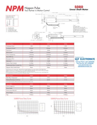
Serial Number
Gap
Coil End Bore
Total Length
Total Length
Motor Cable
Length
Motor Cable
Length
Label Mounting Surface
Movable Length
Forcer Length Stroke Length
Forcer Screw Pitch
Support Length
Setting Pitch
Bending Radius
dep
Serial Number
Gap
Coil End Bore
Label Mounting Surface
Movable Length
Forcer Length Stroke Length
Forcer Screw Pitch
Support Length
Setting Pitch
Bending Radius
dep
Linear Shaft Motor
Unless Otherwise Specified:
Dimensions are in mm
Tolerances are as follows:
Dimension (mm)
- 6
7 - 30
31 - 120
121 - 315
316 - 1000
1001 - 2000
2000 -
Tolerance (mm)
±0.1
±0.2
±0.3
±0.5
±0.8
±1.2
±1.5
Electrical Specs S080D S080T S080Q
Continuous Force1 1.8N 2.7N 3.5N
Continuous Current1 0.8Arms 0.8Arms 0.8Arms
Peak Force2 7.2N 10.8N 14N
Peak Current2 3.4Arms 3.4Arms 3.4Arms
Force Constant (Kf) 2.1N/Arms 3.2N/Arms 4.2N/Arms
Back EMF (Ke) 0.7V/m/s 1.1V/m/s 1.4V/m/s
Resistance 25°C,3 4.7Ω 6.8Ω 22.4Ω
Inductance3 0.7mH 1.0mH 1.3mH
Electric Time Constant 0.149ms 0.147ms 0.144ms
Fundemental Motor Constant (Km) 0.98N√W 1.23N√W 1.39N√W
Magnetic Pitch (North-North) 30mm 30mm 30mm
All specifications are for reference only. Specifications may change depending on servo driver selected. Consult Nippon Pulse.
1) Based on a temp rise of coil surface of 110°K over 25°C ambient temperature stalled forcer, and no external cooling or heat sinking
Addition of 25 cm x 25 cm x 2.5 cm aluminum heat sink increases continuous force by 20%
2) Can be maintained for a maximum of 40 seconds, higher forces and current possible for short periods of time, consult Nippon Pulse
3) All winding parameters listed are measured line-to-line (phase-to-phase)
Thermal Specs S080D S080T S080Q
Max Phase Temperature4 135°C 135°C 135°C
Thermal Resistance (Coil) (Kq) 3.2°C 22.9°C 17.3°C
4) The standard temperature difference between the coil and the forcer surface is 10°C
Forcer Specs S080D S080T S080Q
Forcer Length (A) 40mm 55mm 70mm
Forcer Width 20mm 20mm 20mm
Forcer Screw Pitch (P) 34mm 49mm 64mm
Forcer Weight 0.05g 0.06g 0.08g
Gap 0.50mm 0.50mm 0.50mm
Force - Duty Curve
S 080D
Force - Duty Curve
S 080Q
S080D Force Duty Curve S080Q Force Duty Curve
* Note 1
Cable length 300mm
The bending radius of the motor cable
should be 10.72 mm (wire diameter 1.34 * 8)
as suggested by the wire manufacturer.
This radius should be maintained. Use
supplied connector to attach the proper
high flex cable as required by your application.
L = See Shaft Length
L1 = Usable Stroke + A
L2 = See Shaft Support Length
A = See Moving Coil Length
P = See Moving Coil Screw Pitch
16
14
12
10
8
6
4
2
0
0 10 20 30 40 50 60 70 80 90 100
Force (N)
Duty(%)
2 0 °C
4 0 °C
6 0 °C
8 0 °C
1 1 0 °C
35
30
25
20
15
10
5
0
0 10 20 30 40 50 60 70 80 90 100
Force (N)
Duty(%)
Sold & Serviced By:
2 0 °C 4 0 °C
6 0 °C 8 0 °C
1 1 0 °C
ELECTROMATE
Toll Free Phone (877) SERVO98
Toll Free Fax (877) SERV099
www.electromate.com
sales@electromate.com
2. Shaft Length Shaft Mass
Stroke S080D S080T S080Q
25 85mm 100mm 115mm
50 110mm 125mm 140mm
100 160mm 175mm 190mm
150 210mm 225mm 240mm
200 260mm 275mm 290mm
250 310mm 325mm 340mm
300 360mm 375mm 390mm
Shaft Diameter (D) - 8mm ±0.1
Total Length (L)=Stroke (S)+Forcer Length (A)+(Support Length (L2)x2)
Support and Bending
Stroke Support Length Max. bending
All 10mm 0.05mm
Lead Wire
Wire Type UL 1430
Wire AWG 28
U Phase Red
V Phase White
W Phase Black
300mm lead wire bare leads
The bending radius of the motor ca-ble
should be 10.72mm as suggested
by the wire manufacturer.
Connector (Motor Cable)
Receptacle Housing XMR-03V
Plug Housing XMP-03V
Retainer XMS-03V
Pin Contact SXM-001T-P0.6
Socket Contact SXA-001T-P0.6
To be installed by the user
S080
Linear Shaft Motor
Tandem Forcer
Forcer Spacing Distance
Forcer Spacing Distance
Spec S080T S080Q
Forcer Spacing Distance 5mm 5mm
Pole (N/S) Distance 15mm 15mm
Forcer Length 55mm 70mm
Flip Forcers No Yes
CE Type Motor Cable
Sensor Cable Specs
Shaft Size (D) Forcer Size (A) Usable Stroke Options Options
S — 080 — X — XXXX — XX — XX
D: Double (2) windings
T: Triple (3) windings
Q: Quadruple (4) windings
25-300mm ST: Standard Blank: Standard
FO: Forcer Only
SO: Shaft Only
XX: Two digit for custom motor
Part Numbering System
Stroke S080D S080T S080Q
25 0.02kg 0.03kg 0.03kg
50 0.03kg 0.04kg 0.04kg
100 0.05kg 0.05kg 0.06kg
150 0.07kg 0.07kg 0.08kg
200 0.08kg 0.09kg 0.1kg
250 0.1kg 0.11kg 0.11kg
300 0.12kg 0.12kg 0.13kg
Wire Type UL 1330
Wire AWG 24
U Phase Red
V Phase White
W Phase Black
Ground Wire UL 1330
Wire AWG 20
Frame Ground Green/Yellow
300mm lead wire bare leads
The bending radius of the motor cable
should be 16.96mm as suggested by the wire
manufacturer.
* Note 1
The bending radius of the motor cable should be 10.72
mm (wire diameter 1.34 * 8) as suggested by the wire
manufacturer. This radius should be maintained. Use
supplied connector to attach the proper high flex cable
as required by your application.
Hall Effect Cable
Wire Type UL 1430
Wire AWG 28
VCC Red
GND Black
Sensor 1 White
Sensor 2 Blue
Sensor 3 Yellow
400mm lead wire bare leads
The bending radius of the motor ca-ble
should be 10.72mm as suggested
by the wire manufacturer.
Hall Effect Specs
Wire Type UL 1430
Wire AWG 28
VCC Red
GND Black
Sensor 1 White
Sensor 2 Blue
Sensor 3 Yellow
The bending radius of the sensor cable should be
R10.72 mm (wire diameter 1.38 * 8) as suggested
by the wire manufacturer. This radius should be
maintained. Attach the proper high flex cable as
required by your application.
Sold & Serviced By:
ELECTROMATE
Toll Free Phone (877) SERVO98
Toll Free Fax (877) SERV099
www.electromate.com
sales@electromate.com