SQL Database Design For Developers at php[tek] 2024
Inertia dynamics pb1225fhd_specsheet
1. Brake
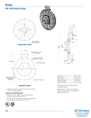
PB-1225 Heavy Duty
MAGNET VIEW
Removable plug in ends
for 1/2" conduit.
.358/.338 dia. (6) holes
equally spaced on 7.250 dia.*
* Mounting holes are within .010 of true position
relative to pilot diameter.
170
1.546
4.093
12.671 Dia.
Max.
Dia.
Shaft Size .750 – 2.687
Static Torque 465 lb. ft.
Maximum Speed 3,000 rpm
Standard Voltage D.C. 6, 24, 90
ARMATURE VIEW
Customer Shall Maintain:
1. Squareness of magnet mounting face with
armature shaft within .006 T.I.R.
2. Concentricity of magnet mounting pilot diameter
with armature shaft within .010 T.I.R.
5/16-18
UNC-3A
.562 1.640
.562
7.531
.921
.062
.234
2.500
2.687
4.156 Max.
See page 252 for
details on Bushings.
.358/.338 dia. (8) holes
equally spaced on
13.000 dia.*
6.378/6.376 Pilot Dia.
3.750
13.875/12.871 Pilot Dia.
8.687 Max.
® U
L
All dimensions are nominal unless
otherwise noted.
Information on inertia and weights
begins on page 239. Coil data is on
pages 250 and 251.
Sold & Serviced By:
ELECTROMATE
Toll Free Phone (877) SERVO98
Toll Free Fax (877) SERV099
www.electromate.com
sales@electromate.com
2. Brake
PB-1225 Heavy Duty
How to Order:
1. Specify Bore Size for Item 2.
2. Specify Inside Mounted for Items 5A and 6A or Outside
Mounted for Items 5B and 6B.
3. Specify Voltage for Item 6A or 6B.
4. See Controls Section.
Example:
PB-1225 Clutch per I-25607 -
90 Volt, 1-1/2" Bore, Inside Mounted
These units, when used in conjunction with the correct
Warner Electric conduit box, meet the standards of UL508
and are listed under guide card #NMTR, file #59164. These
units are CSA certified under file #LR11543.
171
1
(Shipped
Assembled)
1-5
1-1
1-2
1-4
1-3
3
4
2
6A
5A
7
7
6B
6A-1
5B
6B-1
Drawing I-25607
Item Description Part Number Qty.
1 Armature & Splined Adapter 5323-111-001 1
1-1 Armature 5323-111-034 1
1-2 Splined Adapter 104-0010 1
1-3 Autogap Accessory 5323-101-002 1
1-4 Screw 797-0281 4
1-5 Locknut 661-0005 4
2 Bushing* 1
3/4" to 2-11/16" Bore 180-0026 to 180-0057
3 Splined Hub 540-0064 1
4 Retainer Ring 748-0005 1
5A Mounting Accessory - I.M. 5321-101-001 1
5B Mounting Accessory - O.M. 5321-101-002 2
6A Magnet - Inside Mounted 1
6 Volt 5313-631-005
24 Volt 5313-631-006
90 Volt 5313-631-007
†90 Volt 5313-631-001
6A-1 Terminal Accessory 5311-101-001 1
6B Magnet - Outside Mounted 1
6 Volt 5313-631-010
24 Volt 5313-631-012
90 Volt 5313-631-011
†90 Volt 5313-631-002
Item Description Part Number Qty.
6B-1 Terminal Accessory 5311-101-001 1
7 Conduit Box 5200-101-011 1
*See page 252 for specific part numbers.
Refer to Service Manual P-209.
†Optional LK facing available. For more information, see
page 232.
Sold & Serviced By:
ELECTROMATE
Toll Free Phone (877) SERVO98
Toll Free Fax (877) SERV099
www.electromate.com
sales@electromate.com