1. Clutch Coupling
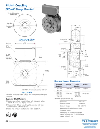
SFC-400 Flange Mounted
For Bore & Keyway sizes
see chart below.
Std. Arm.
Removable
plug in ends
for 1/2"
conduit.
Customer Shall Maintain:
1. Squareness of field mounting face with rotor shaft within
.003 T.I.R. measured at pilot diameter.
2. Concentricity of field mounting pilot diameter with rotor
mounting shaft within .003 T.I.R.
3. Rotor and armature shafts in line within .003 T.I.R. All dimensions are nominal unless
102
.671
.015 When New
Bore and Keyway Dimensions
.093
Armature Keyway Rotor Keyway
Bore Dia. Bore Dia.
.501/.500 .125 x .062 .501/.500 .125 x.062
*.563/.562
.626/.625 .626/.625
*.688/.687 .187 x .093 .751/.750 .187 x .093
.751/.750 .876/.875
.876/.875 1.001/1.000
*Available on special order only
Static Torque 270 lb. in.
Maximum Speed 4,500 rpm
Standard Voltage D.C. 6, 24, 90
ARMATURE VIEW
3.750
FIELD VIEW
4.250 Sq.
4.687
*Mounting holes are within .010 of true position relative to pilot
diameter.
1.875
1.873
Pilot Dia.
1/4-20
UNC-3A
1.250
(Std.)
.328
.015
3.562
.609 Max.
.328 Max.
.187 (Std.)
.218 (Anti.)
.250
1.640
(Anti.)
1.546
.937
4.234 .875
Max.
Dia.
.187 (Std.)
.218 (Anti.)
.828 1.312
1.500
1.50
2.328/2.359
.192/.182
1.125
Antibacklash
Arm.
For Bore &
Keyway
sizes see
chart below.
45°
5.626
5.623
Pilot Dia.
.296/.280 dia. (4) holes equally spaced on 5.000 dia.*
® U
L
otherwise noted.
Information on inertia and weights
begins on page 239. Coil data is on
pages 250 and 251.
Sold & Serviced By:
ELECTROMATE
Toll Free Phone (877) SERVO98
Toll Free Fax (877) SERV099
www.electromate.com
sales@electromate.com
2. 1A-1
1A-3
1A
1A-2
2
3
SFC-400 Flange Mounted
5
3-1
4
1B
Clutch Coupling
103
Drawing I-25697
How to Order:
1. Specify Type of Armature Desired.
2. Specify Bore Size for Item 1A-1 or 1B and Item 2.
3. Specify Voltage for Item 3.
4. See Controls Section.
Example:
SFC-400 Clutch Coupling per I-25697 - 90 Volt
3/4" Armature Hub Bore
3/4" Rotor Bore
These units, when used in conjunction with the correct
Warner Electric conduit box, meet standards set forth in
UL508 and are listed under guide card #NMTR2, file
#59164.
These units are CSA certified under file #LR11543.
Refer to Service Manual P-200.
Item Description Part Number Qty.
1A Armature and Hub
1A-1 Armature Hub 1
1/2" Bore 5104-541-002
5/8" Bore 5104-541-004
3/4" Bore 5104-541-006
7/8" Bore 5104-541-007
1A-2 Armature 5125-111-001 1
1A-3 Release Spring 5104-101-003 1
1B Antibacklash Armature 1
1/2" Bore 5367-111-003
5/8" Bore 5367-111-005
3/4" Bore 5367-111-007
7/8" Bore 5367-111-008
2 Rotor 1
1/2" Bore 5104-751-033
5/8" Bore 5104-751-034
3/4" Bore 5104-751-035
7/8" Bore 5104-751-036
1" Bore 5104-751-037
3 Field 1
6 Volt 5104-451-032
24 Volt 5104-451-033
90 Volt 5104-451-034
Item Description Part Number Qty.
3-1 Terminal Accessory 5103-101-002 1
4 Conduit Box 5200-101-010 1
5 Mounting Accessory 5104-101-002 1
Sold & Serviced By:
ELECTROMATE
Toll Free Phone (877) SERVO98
Toll Free Fax (877) SERV099
www.electromate.com
sales@electromate.com